

Page 1
MITSUMI
RGB Video Amplifier for Monitors MM1203
RGB Video Amplifier for Monitors
Monolithic IC MM1203
Outline
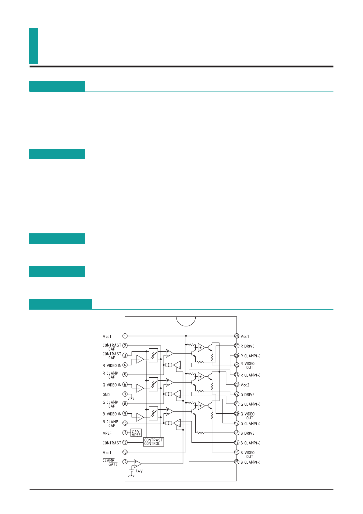
This IC is a wideband video amplifier system developed for high resolution RGB color monitors. In addition to
the three matched video amps, it has three gate control differential input black level comparators for
luminance adjustment, and three matched attenuator circuits for contrast adjustment. Each video amp has
maximum gain setting (AV=4~10) and a drive pin for trimming. The reference voltage supply for video input is
built in.
Features
1. Three built-in wideband video amps (70MHz @ -3dB)
2. Current consumption 65mA typ.
3. Matched (±0.5dB) contrast adjustment attenuators built in
4. Built-in luminance adjustment comparators using external gate control
5. Gain of each video amp controlled independently
6. Built-in video input reference voltage
7. Low impedance output driver
Package
DIP-28B (MM1203ND)
Applications
1. Display monitors
Block Diagram
Page 2
MITSUMI
RGB Video Amplifier for Monitors MM1203
Pin Description
Pin no. Pin name Function Pin no. Pin name Function
1 V
CC1VCC1 15 B CLAMP (+) B clamp input (+)
2 CONTRAST CAP Contrast capacitor 16 B VIDEO OUT B video output
3 CONTRAST CAP Contrast capacitor 17 B CRAMP (
-
) B clamp input (-)
4 R VIDEO IN R video input 18 B DRIVE B drive
5 R CLAMP CAP R clamp capacitor 19 G CLAMP (+) G clamp input (+)
6 G VIDEO IN G video input 20 G VIDEO OUT G video output
7 GND GND 21 G CLMP (
-
) G clamp input (-)
8 G CALMP CAP G clamp capacitor 22 G DRIVE G drive
9 B VIDEO IN B video input 23 V
CC2VCC2
10 B CLAMP CAP B clamp capacitor 24 R CLAMP (+) R clamp input (+)
11 VREF
12 CONTRAST Contrast control 26 R CLAMP (
13 V
14 CLAMP
CC1VCC1 27 R DRIVE R drive
---------------------------------------------------------------------------------
------------------------------------------------------------------
GATE
Absolute Maximum Ratings
Video input reference voltage
----------------------------------------------------------------------------------------------
Clamp gate
input 28 VCC1VCC1
(Ta=25°C)
25 R VIDEO OUT R video output
-
) R clamp input (-)
Item Symbol Ratings Units
Storage temperature T
Operating temperature T
Power supply voltage V
Pin input voltage V
Video output current I
Allowable loss P
Electrostatic breakdown
Pin temperature
9 2kV
*
10 265 °C
*
Recommended Operating Conditions
Item Symbol Conditions Min. Typ. Max. Units
Operating power supply voltage
VCC 10.8 12.0 13.2 V
STG
OPR
CC 13.5 V
IN GND
O 28 mA
d 2.5 W
-
55~+150 °C
-
0~+70 °C
<
<
IN
CC V
V
V
=
=
(Ta=°C)
Page 3

MITSUMI
RGB Video Amplifier for Monitors MM1203
DC Electrical Characteristics
Item Symbol Measurement conditions Min. Typ. Max. Units
Consumption current I
Video input reference voltage V
Video input bias current I
Clamp gate input voltage L V
Clamp gate input voltage H V
Clamp gate input current L I
Clamp gate input current H I
Clamping capacitor charge current I
Clamping capacitor discharge current I
Video output voltage L V
Video output voltage H V
Video output offset difference 1 V
Video output offset difference 2 V
(Except where noted otherwise, Ta=25°C, VCC1=VCC2=12V,
V12=6V, V14=0V, V15=2V, S1, 2, 3=OFF)
CC1 only VCC16585mA
REF 2.2 2.4 2.6 V
B 5.0 20 µA
CGL 0.8 1.2 V
CGH 1.6 2.0 V
CGL V14=0V
CGH V14=12V 0.005 1.0 µA
CL+ V5, 8, 10=0V 500 850 µA
CL
-
OL V5, 8, 10=0V 0.9 1.25 V
OH V5, 8, 10=5V 8.2 8.9 V
OF1 V15=2V
OF2 V15=4V
V5, 8, 10=5V
*
*
2 ±0.5 ±50 mV
2 ±0.5 ±50 mV
-
0.5-0.5 µA
-
500-850 µA
AC Electrical Characteristics
Item Symbol Measurement conditions Min. Typ. Max. Units
Video amp gain A
Gain attenuation 1 A
Gain attenuation 2 A
Gain matching A
Gain fluctuation matching 1 A
Gain fluctuation matching 2 A
Video amp distortion THD V12=3V, V
Video amp frequency bandwidth f
Output rise time t
Output fall time t
Crosstalk 1 V
Crosstalk 2 V
Notes:
1 VCC power supply pins 1, 13, 23 and 28 are connected to each other externally.
*
2 Measure offset voltage between any two amps.
*
3 Measure gain difference between any two amps. VIN=1VP
*
4 Measure attenuation amount relative to Av max., and quantify the difference between any two amps.
*
5 The voltage at which V12 low is -40dB relative to AV max. for attenuation.
*
6 Mount on printed board with ground shield on both sides.
*
7 -3dB cutoff frequency from video amp gain.
*
8 Input a signal to any amp and terminate input for the remaining two amps (use resistor that corresponds
*
to signal source load), then measure output.
9 Human model. Discharge via 1.5kΩ from 100pF capacitor.
*
10 Solder for 10 seconds.
*
(Except where noted otherwise, Ta=25°C, VCC1=VCC2=12V,
V12=12V, V14=0V, V15=4V, fin=10kHz, S1, 2, 3=ON)
V VIN=560mVP-P 4.5 6.0 V/V
V1 V12=5V, VIN=560mVP
V2 V12=2V, VIN=560mVP
VMAT
VM1 V12=5V
VM2 V12=V12LOW
BW VIN=100mVrms
r VOUT=4VP
f VOUT=4VP
SEP1 f=10kHz, VIN=1VP
SEP2 f=10kHz, VIN=1VP
-
P
3 0.5 1.0 dB
*
*3 *
OUT=1VP-P 0.5 %
-
-
-
P
-
12.5-10-7.5 dB
-
P
4 0.1 0.5 dB
5 0.3 dB
*3 *
7 70 120 MHz
*6 *
P
65µS
*
P
67µS
*
-
P
8
*
-
P
*6 *
8
-
40 dB
-
65 dB
-
46 dB
Page 4

MITSUMI
Measuring Circuit
RGB Video Amplifier for Monitors MM1203
Page 5

MITSUMI
Measuring Circuit
RGB Video Amplifier for Monitors MM1203
Page 6

MITSUMI
Gain - Frequency
(VOUT=4VP
-
P)
100k 1M 10M 100M 1G
18
16
14
12
10
0
Frequency (Hz)
Gain (dB)
Attenuation - Contrast Voltag
0123456789101112
-
60
-
50
-
40
-
30
-
20
-
10
0
10
Contrast voltage (V)
Attenuation (dB)
Characteristics
RGB Video Amplifier for Monitors MM1203
Gain-Frequency
Attenuation-Contrast Voltage
 Loading...