

Featur es an d Be n efi ts
g
y
g
(
g
y
y
g
g
q
y
g
y
g
y
y
y
g
g
q
g
g
g
g
“Soft Start” Eliminates Current Surges
rated Design Eliminates External Components
Inte
Drives Virtuall
Any Resistive or Inductive Load
Built–in Thermal Protection
ital Design For Stable Triac Contro l
Di
Immune to Lifetime and Thermal Drift
Low Power Cons umption
50Hz/60Hz Operation
Applications
AC Light Dimmer
Soft-Start AC Motor Controller
Variable-Speed AC Motor Controller
MLX9 0805
Intelligent Triac Controller
Ordering Information
Part No. Temperature Suffix Package version Temperature Range
MLX90805 S A -x 0C to 85C
MLX90805 S L -x 0C to 85C
The customer specific version code
the end of the orderin
number.
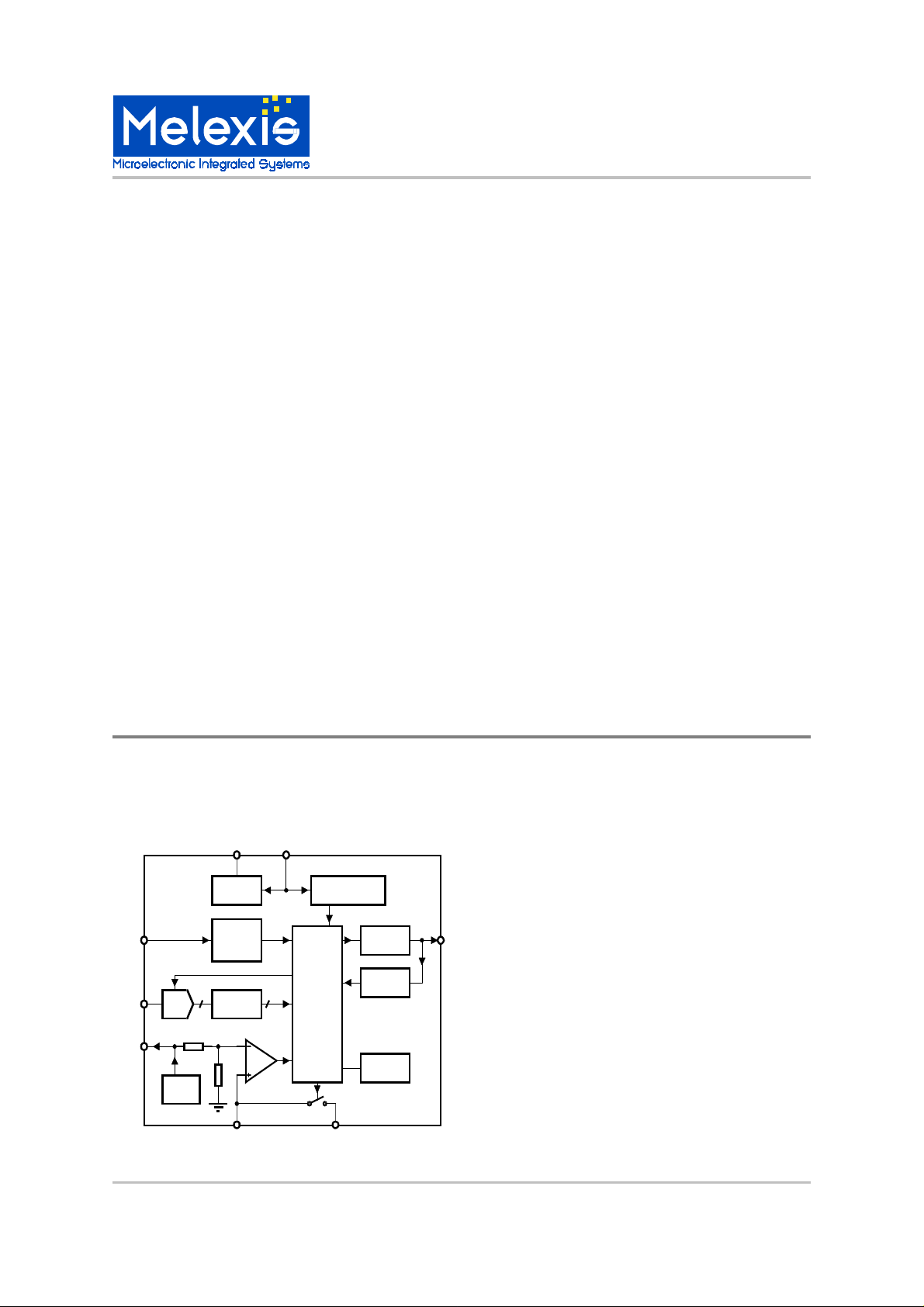
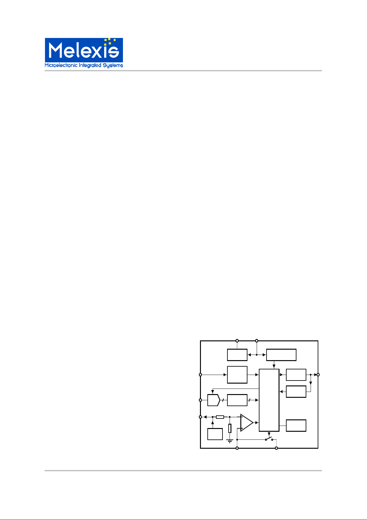
Functional Diagram
Vss Vdda
90805
Power monitorin
and reset
Logic
ZCD
SET
Vref
ADC
Vref
Voltage
regulator
zero
crossin
detector
Lookup
ROM
Vref/2
COMP
defining the options) is indicated with 1 character at
Description
The MLX90805 is a power control IC ideall
resistive or inductive load
ned primarily for starting and
hts.
purpose is to provide a “soft start”
current inrush. The triac is
changing the option bits.
function of the 90805 is proper
uency locked loop for
Triac driver
Auto
retriggerin
Options
for control of an
ulated by a triac.
re
The chip was desi
speed control of AC motors, but will work e
with an
Incandescent li
The c hip’s pr i m ar
for a motor , prev entin
controlled b
maximum power. Start rate can be varied from 0.5
sec. to 3 sec, b
The secondar
nition of the triac for inductive and resistive loads,
i
while keepin
minimum.
Added features include a fre
stable i
Inductive or resistive load such as
a linear “ramp” from minimum to
the triac’s current consumption to a
nition point.
suited
ually well
THP FB
MLX902xx Name of Sensor Rev Y.X 22/Aug/98 Page 1
MLX90805 Intelligent Triac Controller Page 1 Rev 1.2 17/May/00
MLX9 0805
Intelligent Triac Controller
Description of Block Diagram
Voltage Regulator
The chip is supplied from the AC line voltage, by a
half wave rectifi er. The voltage at pin VDDA is limited
to ~ 15.5V. The digital part and some of the peripheral blocks are supplied by internally generated VDD
~ 5V.
Analog Power on Reset
This block tracks the voltage at VDDA, and permits
generation of firing pulses for the triac only if VDDA >
~13V. It is considered otherwise that the motor is not
properly supplied by the mains.
Oscillator
There is an on chip oscillator. All timing constraints
inside the chip are derived from this clock.
FLL
A frequency locked loop circuit is implemented to
obtain a clock frequency from a current controlled
oscillator, by using the mains frequency as a reference. A successive approximation algorithm is used
at start up to minimize the time for the oscillator adjustm ent.
Reference Voltage
This voltage is used to supply the external potentiometer for th e definition of different speed setti ngs.
Logic
This block performs all control functions to realize
time synchronization, smooth soft start, and proper
triac firing, so that motor runs at a defined speed.
Triac Driver
This output is able to drive directly a triac. It defines
the triac gate current and operates as current generator. There is no need of external resistor for current limitation.
Auto Retriggering
This block tracks if the triac is on after each firing
pulse. If the triac is off 20us after a firing pulse, a
new pulse is generated.
Thermal Protection
The chip is able to supply an external protection circuitry, typically an NTC resistor with reference resistor , to track the ambient temperature. If the vol tage at
THP equals Vref/2 the protection is activated and
the chip sets the firing angle defined by the value in
ROM address 1. A resistor connected to pin FB can
introduce hysteresis in the detection level.
Options
Thi s bl ock def i nes di ff eren t mo des of t he chi p o per ation.
ADC
The analog signal from the potentiometer, which defines the s peed s etti ng, i s tra nsfer red into digital by a
4-bit ADC. The reference for the converter is the voltage u sed to supply the p otentiometer.
90805
Vss Vdda
Voltage
regulator
Power monitoring
and reset
ROM
The d igital words from the A DC act as the a ddress of
a ROM table in whi ch th e different f iri ng angles are
programmed. This means that 16 different firing angles can be selected.
ZCD
SET
ADC
zero
crossing
detector
Lookup
ROM
Logic
Triac driver
Auto
retriggering
Zero Cross
Vref
Vref/2
COMP
THP FB
Options
This block detects the moments when mains voltage
Vref
crosses zero level. An accurate detection allows
good synchronization, so firing pulses driving the
triac can be generated at the right moment.
MLX90805 Intelligent Triac Controller Page 2 Rev 1.2 17/May/00
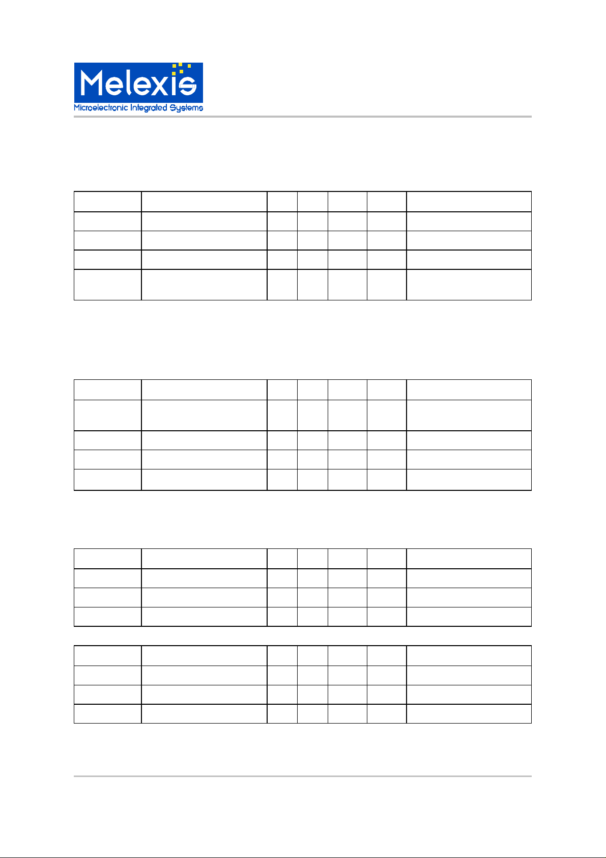
MLX90805 Electrical Specifications
Symbol
Description
Min Typ Max Unit Condition
Tamb
Ambient temperature
0 85 °C
Tch Maximum chip temperature
150 °C
Rth Thermal resistance
110
°C/Ω DIP8 or SOP8 package
IDDAm
Maximum allowed source su
p-
ply current
10 mA
Drivers off, all the current flows
in the chip
Symbol
Description
Min Typ Max Unit Condition
VDDA
Voltage applied at the supply
pin 14 16 18 V IDDA = 5mA
VDD Internal 5V supply
4.6 5.0 5.4 V
IDDA Current consumption
3 mA
VDDA = 14V
VREF
For external circuitry
4.6 5 5.4 V IREF = 8mA
g
Symbol
Description
Min Typ Max Unit Conditions
Vdporh
High level threshold
2.5 V Vdporl
Low level threshold
2.0 V Vdphyst
Hysteresis
0.5 V
Symbol
Description
Min Typ Max Unit Condition
Vaporh
High level threshold
12 13 14 V Vaporl
Low level threshold
9 10 11 V Vaphyst
Hysteresis
2 3 4 V
Environmental Conditions
Analog Fea tures
Power Sup ply
High voltage supply should be applied between VDDA and VSS.
MLX9 0805
Intelligent Triac Controller
Power On Reset
This block ensures a correct sta r t of the digital part.
The reset si
MLX902xx Name of Sensor Rev Y.X 22/Aug/98 Page 3
MLX90805 Intelligent Triac Controller Page 3 Rev 1.2 17/May/00
nal goes up for VDD > Vdporh and down for VDD < Vdporl.
MLX9 0805
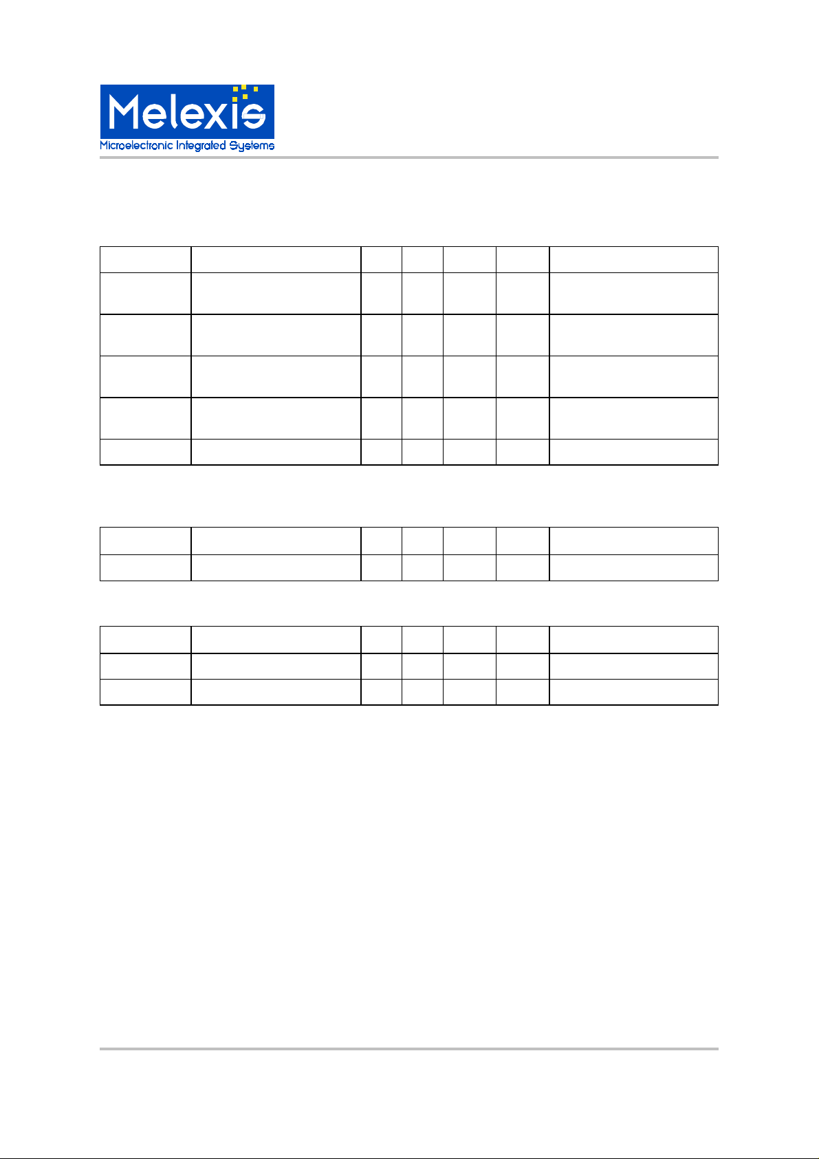
Symbol
Description
Min Typ Max Unit Conditions
Vzc1h
High level threshold 1
VDDA
+0.5 V Vzc1l
Low level threshold 1
VDDA
-
0.5 V Vzc2h
High level threshold 2
VDDA
-
1.5 V Vzc2l
Low level threshold 2
VDDA
-
2.5 V Rzc External resistor
470
kΩ
Vline = 230VAC typ
Symbol
Description
Min Typ Max Unit Conditions
ITRG Triac gate current
30 60 90 mA
VDDA > Vaporh
Symbol
Description
Min Typ Max Unit Conditions
Resolution
4
bits
VREF
Reference voltage
4.6 5 5.4 V
Intelligent Triac Controller
Zero Cross Detector
This detector contains two comparators with hysteresis. The first comparator has its reference at VDDA. The
reference of the second one is VDDA-1V.
Triac (Ignition) Driver
This driver operates as a current generator to fire the triac ON.
ADC
MLX90805 Intelligent Triac Controller Page 4 Rev 1.2 17/May/00

MLX9 0805
j
g
y
g
g
g
y
y
g
g
g
g
g
g
(
g
g
g
g
y
y
y
g
g
g
y
g
g
g
y
g
y
g
q
g
gg
g
(
g
g
y
g
(
g
y
g
y
y
y
g
g
(FB)
(FB)
Intelligent Triac Controller
Digital F eat ur e s
Debounce of ADC
The result from the pot entiometer reading must not
ump f rom one po s ition to the other , therefore a special debouncin
compares the c urrent value from the ADC wi th the
previous one. The new value is accepted onl
absolute difference between the new and the previous value is
Power Settings (ROM table)
The ADC output data is applied after debouncing at
the address bus of the ROM and the correspondin
power settin
[9: 0]. Th e co nten t of th e RO M ca n be d efi ned fr eel
it does not need to be linearl
the pot enti omet er s etti n
tion to the other, the phase an
new position via the soft start procedure, avoidin
abrupt chan
For pro
ROM table, foll owin
in msec) is the delay from the prev ious zero cross -
to th e mom ent of ignition:
in
f.e.: for a phase an
mains, and thus:
Note:
The value should not be negative: very small values
can not be pro
is designed. The debounce circuit
if the
reater then 1 LS B.
s are av aila ble at its d ata out put S ETP
or continuous. When
is changed from one posi-
le is moved to the
es.
ramming the different speed settings in t he
formula can be used, given ti
102]0:9[ −••= FmainstiROMi
le of 50%, ti = 5msec for a 50Hz
490105025]0:9[ =−••=ROMi
rammed.
Firing
The soft start circuit generates a predefined set of
values for the i
compared with the value of a down counter, which is
clocked b
and is cleared at be
mains. When the counter value becomes e
IGN the firin
GATE with duration 20us, 40us, 80us or 320us. This
dur ation ca n be chosen with opt ion DUTS [1:0]. The
eri ng circuit checks whether the triac is ON, if
retri
not additional firin
wit h respec t to the en d of the p revio us firi ng pulse)
until firin
Thermal Protection
An external circuitry supplied by VREF defines the
:
e at pin THP. This voltage is proportional to
volta
Tamb. It is tracked b
ferred to V REF/2. The tracki n
When the switch is ON
checks if Tamb is
es, the motor is driven to operate at the speed defined at the first ROM address. Durin
the switch is OFF, the chip checks what kind of mode
is defined b
potentiometer connection. A reconnection of the element s used f or therm al pr otecti on is n eeded on l
define the active mode of operation.
The temperatures for which thermal protection becomes active or not are defined b
ment s, keepin
toVREF/2.
In t he ca se when therm al p rotec tio n is n ot used , pi n
THP should be connected to pin FB, which is connected either to Vss or to Vref, dependin
mode.
2-wire mode, if V
3-wire mode, if V
nition angle IG N. Thes e values are
DCLK = 100kHz (the resolution is 10 us)
inning of every half period of
circuit produces an ignition pulse
puls es ar e genera ted every 20us
of the triac.
an internal comparator re-
proc ess is samp led.
see bl o c k di agram), the chip
reater than a predefined value. If
the time wh en
the ext ern al el emen ts: 2-wir e or 3-wir e
the ext ern al el e-
in mind that comparator is referred
= VREF
= VSS
ual to
to
on the
Soft Start
The soft start is initiated after the supply volt age has
been built up. This behavior
start-up for the motor and automaticall
optimum run-up time. The motor is fired initiall
small phase angle, i.e. a delay time very
a ver
close to half the mains period. The phase an
than increasin
pot en t iomet er set t in
the option ATN[4:0]. This option defines the time
b
to increase the phase an
mum. If the phase an
ter, is not the maximum phase an
start run-up time is decreased proportionall
MLX902xx Name of Sensor Rev Y.X 22/Aug/98 Page 5
MLX90805 Intelligent Triac Controller Page 5 Rev 1.2 17/May/00
up to the phase angle defined by the
. The rate of increase is defined
le, selected by the potent iome-
uarantees a gentle
ensures the
wit h
le is
le from minimum to maxi-
le then the soft
.

MLX9 0805
Pin Name
Type Description
1 SET Input Potentiometer input
2
THP Input Thermal protection
3 FB
Input Feed back to create
hysteresis for thermal
protection
4 ZC
Input Zero cross input
5
TRG Output
Triac driver output
6
VSS Supply
Ground
7
VDDA
Supply
Supply, high level
8
VREF
Output
Reference voltage
Rom address
Value
0
590 1 567 2 544 3 522 4 500 5 477 6 456 7 434 8 411 9 387 10 362 11 335 12 305 13 273 14 231 15 112
Intelligent Triac Controller
Pinout
Standard package is 8-pin dual inline package.
(Known as DIP-8, PDIP-8, DIL-8 and PDIL-8)
Precautions
Options
The followin g options are available:
Firing angle definition
The firing angles, and corresponding motor speeds,
can be defined in ROMi[9:0]. This is the ROM table
which is addressed by the ADC reading the
potentiometer setting. The RO M contai ns 16 words
of 10 bits. For programming the different speed
sett ings in the RO M table, f ollowi ng form ula can be
used, given ti (in msec) is the delay from the
previous zero crossing to the moment of ignition:
FmainstiROMi
With: Fmains = frequency of the mains (in Hz)
−••=
102]0:9[
Note:
The value should not be negative: very small values
can not be programmed.
The content of the ROM can be defined freely: it
does not need to be linear or continuous. However
for a proper softstart generation under all conditions,
the value with minimum firing angle (thus maximum
speed) must be in the highest ROM address.
Default v al u es:
Disturbance Immunity
According to pr EN 55014-2
ESD
All I/O pins must withstand the normalized ESD
pulses up to 2kV (100pF / 1.5 kΩ). The pins will be
stressed in both polarities, with respect to the combination of all supply pins.
MLX90805 Intelligent Triac Controller Page 6 Rev 1.2 17/May/00

MLX9 0805
g
g
y
g
g
g
q
g
((
(
g
)
g
g
(
g
DUTS1
DUTS0
Duration in
S 0 0 320 0 1 80 1 0 40 1 1 20
gg
g
y
g
gg
g
y
g
gg
y
g
gg
(
q
y
y g
g
g
g
(
gg
g
g
g
(
q
gg
Intelligent Triac Controller
Maximum phase angle
Independent of the phase angle definitions in the
ROM table, a maximum phase an
This is the phase an
after the power on sequence, and is therefore
atel
the first phase an
This maximum phase an
with the formula:
MIN[9:0] = Tini * 2 * Fmains - 10
With:
Tini = the initial phase an
Fmains = fre
Default value:
Tini = 7 msec and Fmains = 50Hz, thus MIN[9:0] is
690.
uency of the mains (in Hz)
le that will be applied immedi-
le in the soft start sequence.
le is defined in MIN[9:0]
le (in msec)
le can be defined.
Soft start time duration
There are 5 bits ATN[4:0] used to define the duration
of the soft start time. The bits can be calculated with
followin
Ts =
With:
Ts = the duration of the soft start
Tini = the initial phase an
msec
Tmin = the phase an
in the hi
ATTN = bin2dec
and 32.
Default value:
Tini = 8m sec, Tmin = 1.84 m sec, ATTN = 32, thu s Ts
= 3.15 sec.
formula:
Tini – Tmin) * ATTN ) / 62.5
in sec.)
le defined by MIN[9: 0] (in
le corresponding to th e value
hest ROM address (in msec)
ATN[4:0]+1), a value between 2
Firing pulse duration
The duration of the firing pulses can be defined by
the bits D UTS[ 1:0] accordin
The default value is 20 usec.
to following table.
Enable Retriggering
With bit RTRIG set to 1, triac retr iggeri ng is enabled.
The retri
ON, if not additional firin
ever
firin
With bit RTRIG set to 0, tria c retri
For each tri ac firin
dela
previous firin
The default value is tri
ering circuit checks whether the triac is
pulses are generated
20us (wit h respec t to the en d of t he pr eviou s
puls e) until firing of th e tria c.
ering is disabled.
two pul ses ar e genera ted w ith a
of 20 usec (with respect to the end of the
pulse).
ering enabled.
Retriggering Mask
With the option MINA[3:0] it is possible to define a
zone at the end of each half c
e, where it is impossible to generate
volta
ering pulses. This has two purposes:
retri
With some
become
This can eventuall
which will unnecessaril
thus increasin
When
zero crossin
half period. With some
lead to false tri
avoided.
The bits MINA[3:0] are defined accordin
followin
Tmina * 2 * Fmains = MINA[3:0] * 64
With:
Tmina = the phase an
prohibited
Fmains = fre
Default value:
MINA[3:0]=1101'b=13'd and Fmain = 50Hz, this
means th at retr i
non inductive) loads the current can
uite small at the end of each half cycle.
activate the retriggering circuit
enerate additional pulses
the curren t cons umption.
enerating a retr iggeri ng pulse just before the
, this pulse could overlap to the next
non inductive) loads this can
ering at full power and must be
formula:
le from which retriggering is
in msec)
uency of the mains (in Hz)
ering is prohibited a t 8.32ms.
cle of the mains
to the
Soft start only Function regulator
See page 8
µ
2-wire or 3-wire potentiometer
connection.
See pages 9 and 10
MLX902xx Name of Sensor Rev Y.X 22/Aug/98 Page 7
MLX90805 Intelligent Triac Controller Page 7 Rev 1.2 17/May/00

Intelligent Triac Controller
Applications Example - Soft Start Only
N
Cf
Vdda
90805
ZC
VssRZ
TRG
SET
MLX9 0805
L
RM
Soft Start Only
The chip is used to perform smooth soft start of an
electri c al m o t or. It d et ec t s w hen t h e m a in s v ol t ag e i s
applied and generates firing pulses for the triac. The
motor starts running, and the maximum speed (motor
operating at full power) is reached after a predefined
time. This application is defined by fixing V(SET) =
Vref . This means, after s oft star t gener atio n, alwa ys
the maximum speed (corresponding to the highest
ROM address) is sele cte d.
M
MLX90805 Intelligent Triac Controller Page 8 Rev 1.2 17/May/00

MLX9 0805
g
q
g
(
g
y
y
g
g
g
g
g
g
g
y
(
Intelligent Triac Controller
Applications Example - Soft Start with 2-Wire Setting
N
Cf
Vdda
ZC
RZ
L
Vss
RM
TH P Vref FB SET
Soft Start With 2-Wire Setting
The s peed c o nt r ol is p erf o rmed in a d di ti o n to th e s of t
start in this application. A potentiometer in 2-wire
connection is used to define different speed settin
An additional resistor RP with value e
tentiometer is used to keep the ADC input to be ratiometric. In this case, the input si
varies between 0 and VREF/2.
The minimum speed corresponds to a potentiometer
set to its minimum value
speed corresponds to a potentiometer set to its maximum value. When the mains volta
stem, the motor starts running at a speed defi ned
s
the potentiometer, as soon as the soft start time
b
has finished.
The disadvanta
maximum speed settin
lute value of the potentiometer defines the tolerance
of the volta
accurate selection of the maximum speed settin
This can be avoided when usin
tion.
The volta
address a ROM table in which the different phase
les are defined with a 10 bit resolution.
an
The 2 -wir e mode is select ed b
VREF
event ual ly via a r esist or).
e of t he 2- wir e ap pli ca ti on is that , a t
e at the SET input, resulting in a less
e at SET is transferred to a 4 bit value to
i.e. Rpot = 0). Maximum
, the tolerance on the abso-
ual to the po-
nal for the ADC
e is applied to the
the 3- wire a pplic a-
connecting VFB to
s.
90805
R1R2
NTC Pot
RP
TRG
M
Note:
R1, R2 and NTC are only needed for therm al protection, and can be left out otherwise
.
MLX902xx Name of Sensor Rev Y.X 22/Aug/98 Page 9
MLX90805 Intelligent Triac Controller Page 9 Rev 1.2 17/May/00

MLX9 0805
Intelligent Triac Controller
Applications Example - Soft Start with 3-Wire Setting
N
Cf
Vdda
ZC
RZ
L
Vss
RM
Soft Start With 3-Wire Setting
The s peed c o nt r ol is p erf o rmed in a d di ti o n to th e s of t
start in this application. A potentiometer in 3-wire
connection is used to define different speed settings.
The input signal for the ADC varies between 0 and
VREF.
The minimum speed correspond s to a maxi mu m voltage at SET. Maximum speed corresponds to a minimum volt ag e at S ET. W hen t he m ain s vol tag e i s applied to the system, the motor starts running at a
speed defined by the potentiometer, as soon as the
soft star t time has finished.
The v olt age at SET i s tr ansf erred t o a 4 b it va lue t o
address a ROM table in which the different phase
angles are defined with a 10 bit resolution.
The 3-wire mode is selected by connecting VFB to
VSS (eventually via a resistor).
90805
TH P Vref FBSET
NTC
R2
TRG
R1
M
Pot
Note:
R1, R2 and NTC ar e onl y n eeded f or t herm al pr otection, and can be left out otherwise
MLX90805 Intelligent Triac Controller Page 10 Rev 1.2 17/May/00

MLX9 0805
y
Intelligent Triac Controller
Performance of Soft Start Mechanism.
The p lot s ar e a m easur em ent of mot or c urr ent (signal A1) and sp eed (signal A2) during startup for a particular
motor.
In the first plot we have a soft start of approx. 3 seconds.
In the second plot we directl
connect the same motor to the line voltage:
MLX902xx Name of Sensor Rev Y.X 22/Aug/98 Page 11
MLX90805 Intelligent Triac Controller Page 11 Rev 1.2 17/May/00

“A” Package Dimensions
MLX9 0805
Intelligent Triac Controller
0.20
0.38
6.10
7.11
1.1
5
1.7
7
Dimension 8 Leads 16 Leads 18 Leads 20 Leads14 Leads 24 Leads
0.35
0.55
A
2.54
BSC
Min
Max
9.02
10.16
A
18.67
19.68
18.67
19.68
5.33
MAX
2.93
4.06
Notes:
1-All measurements in mm
2-Body dimensions do not include mold
flash or protrusion - not to exceed
0.39
0.15mm
Min
22.35
23.67
24.89
26.92
7.62
BSC
31.24
32.51
10.92
Max
MLX90805 Intelligent Triac Controller Page 12 Rev 1.2 17/May/00

“SO” Package Dimensions
y
MLX9 0805
Intelligent Triac Controller
0.33
0.51
1.27
A
Dimension 8 Leads 14 Leads
Min
A
Max
4.80
5.00
8.55
8.75
0.010 min.
16 Leads
9.80
10.00
3.80
4.00
5.80
6.20
0o to 8
o
Notes:
1-All nominal measurements in millimeters
2-Body dimensions do not include mold flash
or protrusion - not to exceed
0.15mm
2.35
2.65
0.40
1.27
For the lat est version of this doc u m ent ,
Go to our website at:
www.melexis.com
Or for addit i on al informati on
contact Melexis Direct:
USA
Melexis Inc.
41 Locke Road, Concord, NH 03301
Phone: +1 603 223 2362 Fax: +1 603 223 9614
E-mail: sales_usa @melex is.co m
United Kingdom
Silicon Concepts
PCB Lynchborough Road, Hampshire GU30 7SB, United Kingdom
Phone: +44 1428 751 617 Fax: +44 1428 751 603
E-mail: sale s_ u k@ me lexis.co m
Germany
Am Seestern 8, 40547 Düsseldorf, Germany
Phone: +49 211 5360212 Fax: +49 211 5360250
E-mail: sales_de@melexis.com
MLX902xx Name of Sensor Rev Y.X 22/Aug/98 Page 13
MLX90805 Intelligent Triac Controller Page 13 Rev 1.2 17/May/00
France
Melexis France
Tour Arago, 5 rue Bellini, 92806 Puteaux-La-Défense, France.
Phone: +33 1 47 78 11 34 Fa x: +33 1 47 78 06 35
E-mail: sales_fran c e@ me lexis.com
Ital
Dimacred IRL
Via Papa Giovanni XXIII no. 25, 20046 Biassono, Italy
Phone: +39 039 249 4856 Fax: +39 039 491773
E-mail: sale s_italy@melexis.com
Japan
Satori Electric Co., LTD
1-14-10 Shiba, Minato-Ku, Tokyo, Japan
Phone: +81 3 3452 7171 Fax: +81 3 3769 2197
E-mail: sale s_japan@melexis.com
Taiwan
Beechwood Int’l Taiwan Co.
Room 8, 17F, No. 189, Taipei, Taiwan
Phone: +886 2 2739 3322 Fax: +886 2 2739 3090
E-mail: sales_ta i wan@melex is.com
 Loading...