

Page 1

DRIVER CONTROLS
2007 G35 Sedan
Revision: October 2006
A
B
SECTION MIR
CONTENTS
WITH ADP
BASIC INSPECTION ....................................
DIAGNOSIS AND REPAIR WORKFLOW ..........4
Work Flow .................................................................4
FUNCTION DIAGNOSIS ...............................5
DOOR MIRROR SYSTEM ................................... 5
System Diagram ........................................................5
System Description ...................................................5
Component Parts Location . .......................................5
Component Description .............................................6
INSIDE MIRROR SYSTEM .................................. 7
System Description ...................................................7
Component Description .............................................7
DIAGNOSIS SYSTEM (DRIVER SEAT C/U) ......8
Diagnosis Description ......................... ... ...................8
CONSULT-III Function ..............................................8
COMPONENT DIAGNOSIS .........................11
MIRROR SWITCH ..............................................11
Description ..............................................................11
Component Function Check ....................................11
Diagnosis Procedure ........................... ... ... ... .... .......11
Component Inspection ....... .... ... ... ... ........................12
CHANGE OVER SWITCH ..................................14
Description ..............................................................14
Component Function Check ....................................14
Diagnosis Procedure ........................... ... ... ... .... .......14
Component Inspection ....... .... ... ... ... ........................15
DOOR MIRROR MOTOR ...................................16
Description ..............................................................16
Component Function Check ....................................16
Diagnosis Procedure ........................... ... ... ... .... .......16
Component Inspection ....... .... ... ... ... ........................18
MIRRORS
AUTO ANTI-DAZZLING INSIDE MIRROR
CIRCUIT ............................................................
4
Description .......................... ... ....... ...... ....... ...... ........19
Component Function Check ....................................19
Diagnosis Procedure ...............................................19
AUTO ANTI-DAZZLING INSIDE MIRROR
SYSTEM ............................................................
Wiring Diagram — INSIDE MIRROR SYSTEM — ....20
ECU DIAGNOSIS .........................................22
DRIVER SEAT CONTROL UNIT ......................22
Reference Value ......................................................22
Wiring Diagram—AUTOMATIC DRIVE POSI-
TIONER CONTROL SYSTEM— .............................
Fail Safe .................................... ...... ... ....... ...... ........37
DTC Index .......................... ....... ... ...... ....... ...... ........38
AUTOMATIC DRIVE POSITIONER CON-
TROL UNIT ........................................................
Reference Value ......................................................39
Wiring Diagram—AUTOMATIC DRIVE POSI-
TIONER CONTROL SYSTEM— .............................
SYMPTOM DIAGNOSIS ..............................54
NONE OF THE DOOR MIRROR CAN BE OP-
ERATED USING ANY SWITCH ........................
Diagnosis Procedure ...............................................54
DOOR MIRROR DOES NOT OPERATE ..........55
Diagnosis Procedure ...............................................55
AUTO ANTI-DAZZLING INSIDE MIRROR
DOES NOT OPERATE ......................................
Diagnosis Procedure ...............................................56
SQUEAK AND RATTLE TROUBLE DIAG-
NOSES ..............................................................
Work Flow ................................................................57
Inspection Procedure ...............................................59
19
20
27
39
43
54
56
57
C
D
E
F
G
H
I
J
K
MIR
M
N
O
P
MIR-1
Page 2

Diagnostic Worksheet ............................................. 61
Revision: October 2006
2007 G35 Sedan
PRECAUTION ............................................. 63
PRECAUTIONS .................................................63
Precaution for Supplemental Restraint System
(SRS) "AIR BAG" and "SEAT BELT PRE-TEN-
SIONER" ............................. ................. ...................
63
Diagnosis Procedure ..... ... .......................................74
Component Inspection ............................................ 75
DOOR MIRROR MOTOR .................................. 77
Description ..............................................................77
Component Function Check ................................... 77
Diagnosis Procedure ..... ... .......................................77
Component Inspection ............................................ 78
PREPARATION ........................................... 64
PREPARATION .................................................64
Commercial Service Tools .................................... 64
ON-VEHICLE MAINTENANCE ................... 65
PRE-INSPECTION FOR DIAGNOSTIC .............65
Basic Inspection ..................................................... 65
ON-VEHICLE REPAIR ................................ 66
INSIDE MIRROR ................................................66
Exploded View ........................... ... .......................... 66
Removal and Installation ........................................ 66
DOOR MIRROR .................................................67
Exploded View ........................... ... .......................... 67
Removal and Installation ........................................ 67
DOOR MIRROR REMOTE CONTROL
SWITCH .............................................................
Exploded View ........................... ... .......................... 68
Removal and Installation ........................................ 68
68
DISASSEMBLY AND ASSEMBLY ............. 69
AUTO ANTI-DAZZLING INSIDE MIRROR
CIRCUIT .............................................................
Description ..............................................................79
Component Function Check ................................... 79
Diagnosis Procedure ..... ... .......................................79
79
DOOR MIRROR ................................................. 80
Wiring Diagram —DOOR MIRROR SYSTEM — ....80
AUTO ANTI-DAZZLING INSIDE MIRROR
SYSTEM ............................................................
Wiring Diagram — INSIDE MIRROR SYSTEM — ...82
82
SYMPTOM DIAGNOSIS ............................ 84
NONE OF THE DOOR MIRROR CAN BE OP-
ERATED USING ANY SWITCH ........................
Diagnosis Procedure ..... ... .......................................84
DOOR MIRROR DOES NOT OPERATE ........... 85
Diagnosis Procedure ..... ... .......................................85
AUTO ANTI-DAZZLING INSIDE MIRROR
DOES NOT OPERATE ......................................
Diagnosis Procedure ..... ... .......................................86
84
86
DOOR MIRROR .................................................69
Exploded View ........................... ... .......................... 69
Disassembly ........................................................... 69
Assembly ................................................................ 69
WITHOUT ADP
BASIC INSPECTION ...................................
DIAGNOSIS AND REPAIR WORKFLOW ......... 71
Work Flow ........ ... .... ................................................ 71
71
FUNCTION DIAGNOSIS ............................. 72
DOOR MIRROR SYSTEM .................................72
Component Description .......................................... 72
INSIDE MIRROR SYSTEM ................................ 73
System Description ................................................. 73
Component Description .......................................... 73
COMPONENT DIAGNOSIS ........................74
DOOR MIRROR REMOTE CONTROL
SWITCH .............................................................
Description ....................... .......................... ............. 74
Component Function Check ................................... 74
74
SQUEAK AND RATTLE TROUBLE DIAG-
NOSES ...............................................................
Work Flow ............................................................... 87
Inspection Procedure .............................................. 89
Diagnostic Worksheet .............................................91
87
PRECAUTION ............................................ 93
PRECAUTIONS ................................................. 93
Precaution for Supplemental Restraint System
(SRS) "AIR BAG" and "SEAT BELT PRE-TEN-
SIONER" ............................. ....................................
93
PREPARATION .......................................... 94
PREPARATION ................................................. 94
Commercial Service Tools ....................................94
ON-VEHICLE MAINTENANCE .................. 95
PRE-INSPECTION FOR DIAGNOSTIC ............ 95
Basic Inspection .................................. ... .... ... ... ... .... 95
ON-VEHICLE REPAIR ............................... 96
INSIDE MIRROR ................................................ 96
Exploded View ........................................................96
MIR-2
Page 3

Removal and Installation .........................................
Revision: October 2006
2007 G35 Sedan
96
DOOR MIRROR ..................................................97
Exploded View ........................................................97
Removal and Installation .........................................97
DOOR MIRROR REMOTE CONTROL
SWITCH ..............................................................
Exploded View ........................................................98
98
Removal and Installation .........................................98
DISASSEMBLY AND ASSEMBLY ..............99
DOOR MIRROR ................................................99
Exploded View .........................................................99
Disassembly ............................................................99
Assembly ............................ .....................................99
A
B
C
D
E
F
G
H
I
J
K
MIR
M
N
O
P
MIR-3
Page 4

DIAGNOSIS AND REPAIR WORKFLOW
Revision: October 2006
2007 G35 Sedan
< BASIC INSPECTION >
[WITH ADP]
BASIC INSPECTION
DIAGNOSIS AND REPAIR WORKFLOW
Work Flow INFOID:0000000000962307
DETAILED FLOW
1.OBTAIN INFORMATION ABOUT SYMPTOM
Interview the customer to obtain the malfunction information (conditions and environment when the malfunction occurred) as much as possible when the customer brings the vehicle in.
>> GO TO 2.
2.REPRODUCE THE MALFUNCTION INFORMATION
Check the malfunction on the vehicle that the customer describes.
Inspect the relation of the symptoms and the condition when the symptoms occur.
>> GO TO 3.
3.PERFORM “BASIC INSPECTION”
Perform the basic inspection.Refer to MIR-65, "
>> GO TO 4.
Basic Inspection".
4.IDENTIFY THE MALFUNCTIONING SYSTEM WITH “SYMPTOM DIAGNOSIS”
Use “Symptom diagnosis” from the symptom inspection result in step 2. Then identify where to start performing the diagnosis based on possible causes and symptoms.
>> GO TO 5.
5.IDENTIFY MALFUNCTIONING PARTS WITH “COMPONENT DIAGNOSIS”
Perform the diagnosis with “Component diagnosis” of the applicable system.
>> GO TO 6.
6.REPAIR OR REPLACE THE MALFUNCTIONING PARTS
Repair or replace the specified malfunctioning parts.
>> GO TO 7.
7.FINAL CHECK
Check that malfunctions are not reproduced when obtaining the malfunction information from the customer,
referring to the symptom inspection result in step 2.
Is the malfunctioning part repaired or replaced?
YES >> Trouble diagnosis is completed.
NO >> GO TO 3.
MIR-4
Page 5
< FUNCTION DIAGNOSIS >
Revision: October 2006
2007 G35 Sedan
DOOR MIRROR SYSTEM
[WITH ADP]
FUNCTION DIAGNOSIS
DOOR MIRROR SYSTEM
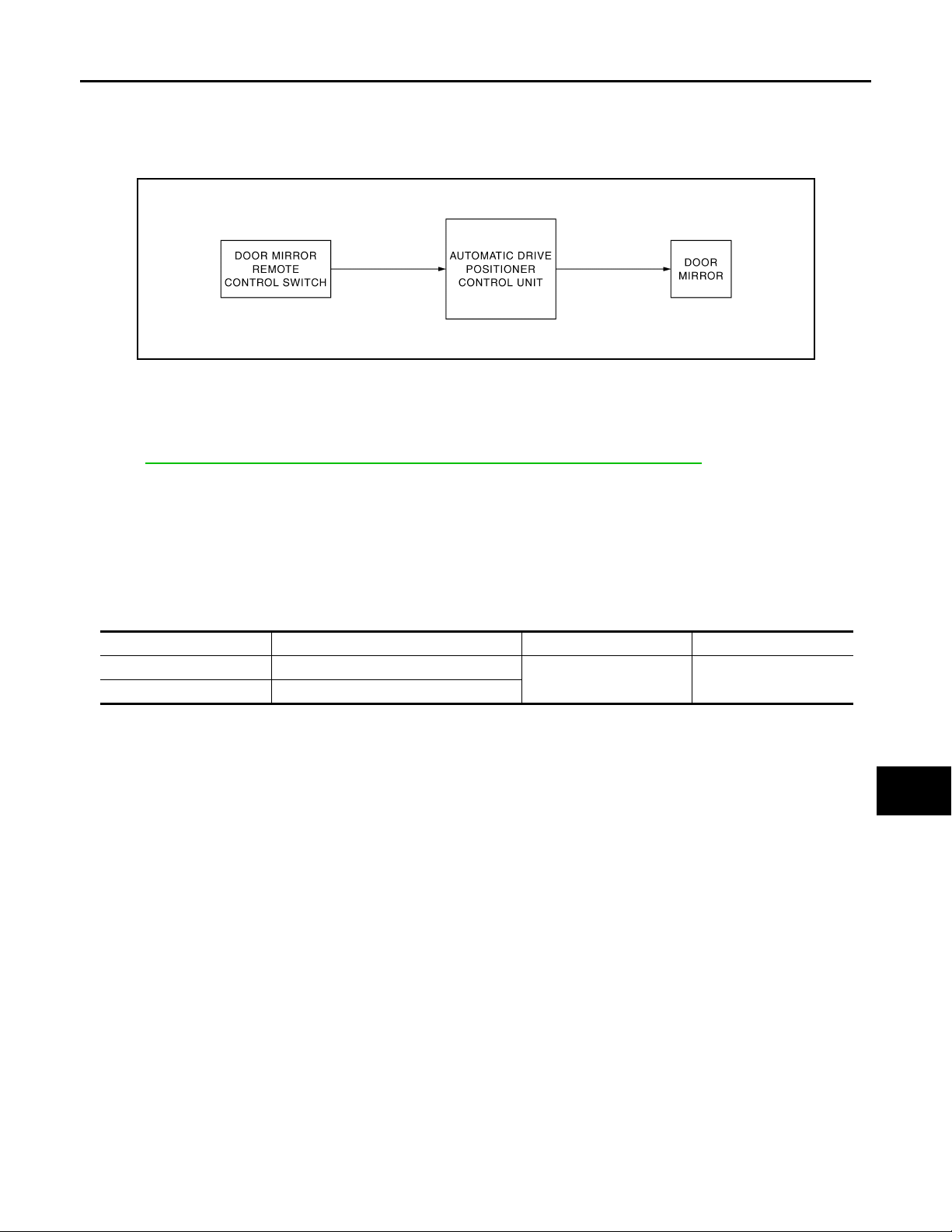
System Diagram INFOID:0000000000962308
JMLIA0006GB
System Description INFOID:0000000000962309
Automatic drive positioner linked operation
Refer to ADP-15, "AUTOMATIC DRIVE POSITIONER SYSTEM : System Description"
Manual operation
• Automatic drive positioner (ADP) control unit receives changeover switch signal and perform the LH/RH
control of door mirror motor that supplies electric power when changeover switch is operated.
• Automatic drive positioner control unit receives mirror switch signal and supplies electric power to door mirror motor when mirror switch is operated.
A
B
C
D
E
F
G
H
INPUT/OUTPUT SIGNAL CHART
Switch Input Signal to ADP ADP function Acutuator
Mirror switch Mirror switch signal
Changeover switch Changeover switch signal
Door mirror motor control Door mirror motor
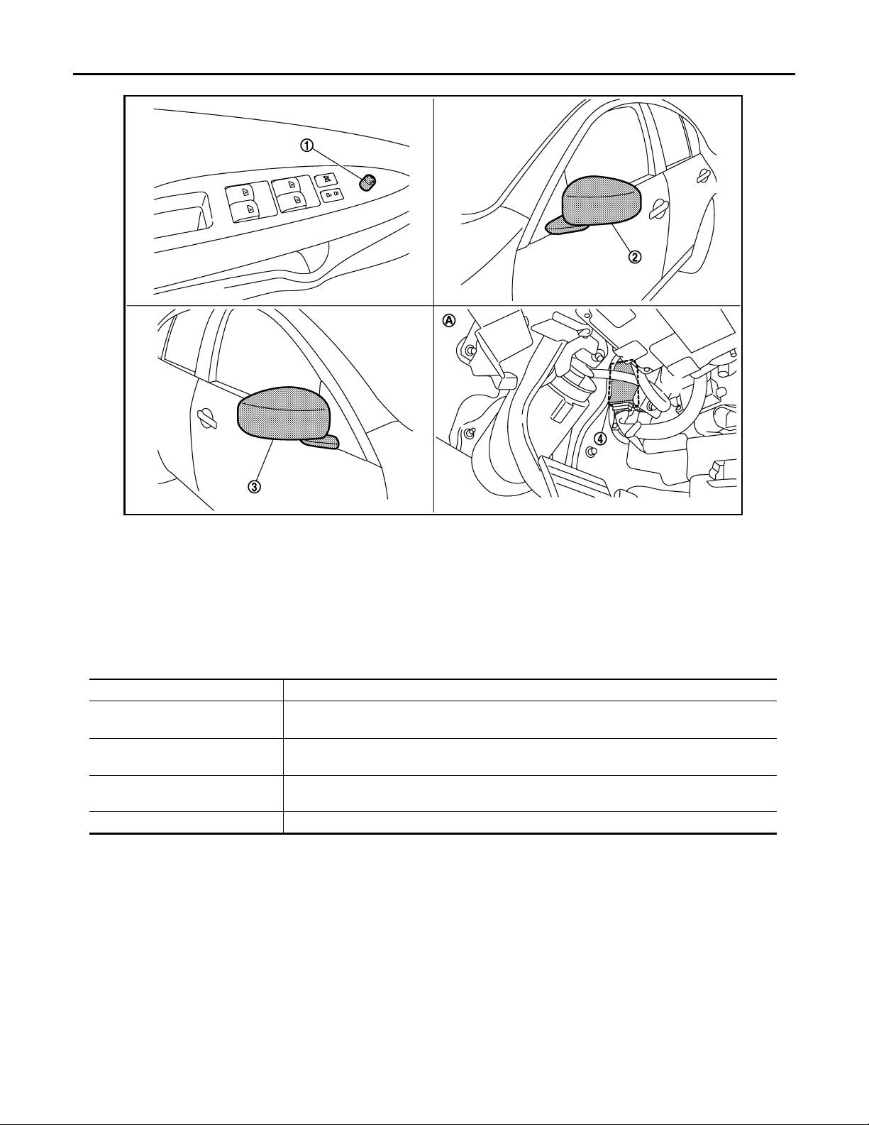
Component Parts Location INFOID:0000000000962310
I
J
K
MIR
M
N
O
P
MIR-5
Page 6
< FUNCTION DIAGNOSIS >
Revision: October 2006
2007 G35 Sedan
DOOR MIRROR SYSTEM
[WITH ADP]
JMLIA0004ZZ
1. Door mirror remote control switch D7 2. Door mirror (driver side) D3 3. Door mirror (passenger side) D33
4. Automatic drive positioner control
unit M51,M52
A, View with instrument driver lower
panel removed
Component Description
Component Function
Automatic drive positioner control
unit
Mirror switch
Changeover switch
Door mirror It makes mirror face operate from side to side and up and down via integrate d motor.
Door mirror is supplied with power after receiving the input of the MIRROR SWITCH and
CHANGEOVER SWITCH.
It transmits mirror face adjust operation to AUTOMATIC DRIVE POSITIONER CONTROL
UNIT.
It transmits the LH/RH control of door mirror th at supplies power to AUTOMATIC DRIVE POSITIONER CONTROL UNIT.
INFOID:0000000000962311
MIR-6
Page 7
< FUNCTION DIAGNOSIS >
Revision: October 2006
2007 G35 Sedan
INSIDE MIRROR SYSTEM
[WITH ADP]
INSIDE MIRROR SYSTEM
System Description INFOID:0000000000962312
It senses the brightness of the headlight of the vehicle to the rear with the sensor integrated into the mirror. It
automatically changes the light transmittance according to the sensed brightness of the light from the headlight.
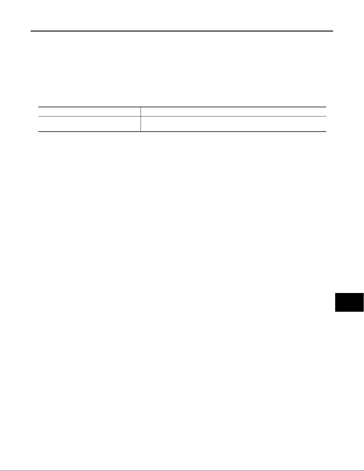
Component Description INFOID:0000000000962313
Component Function
Auto anti-dazzling inside mirror
It automatically changes the light tran smitt ance accordi ng to the bri ghtness of the
light from the headlight of the vehicle to the rear.
A
B
C
D
E
F
G
H
I
J
K
MIR
M
N
O
P
MIR-7
Page 8

DIAGNOSIS SYSTEM (DRIVER SEAT C/U)
Revision: October 2006
2007 G35 Sedan
< FUNCTION DIAGNOSIS >
[WITH ADP]
DIAGNOSIS SYSTEM (DRIVER SEAT C/U)
Diagnosis Description INFOID:0000000000962314
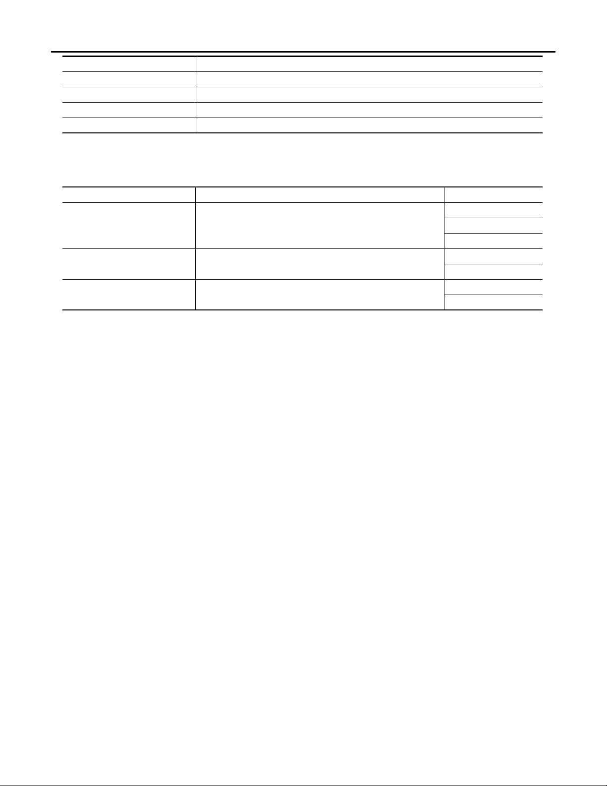
The auto drive positioner system can be checked and diagnosed for component operation with CONSULT-III.
DIAGNOSTIC MODE
Diagnostic mode
[AUTO DRIVE POS.]
WORK SUPPORT Changes the setting of each function.
SELF-DIAG RESULTS Performs self-diagnosis for the auto drive positioner system and displays the results.
DATA MONITOR
CAN DIAG SUPPORT MNTR The result of transmit/receive diagnosis of CAN communication can be read.
ACTIVE TEST Drive each output device.
ECU PART NUMBER Displays part numbers of driver seat control unit parts.
Displays input signals transmitted from various switches and sensors to driver seat control unit in real time.
Description
CONSULT-III Function INFOID:0000000000962315
SELF-DIAGNOSIS RESULTS
Refer to ADP-156, "DTC Index".
DATA MONITOR
Monitor Item Unit
SET SW “ON/OFF” ××ON/OFF status judged from the setting switch signal.
MEMORY SW 1 “ON/OFF” ××
MEMORY SW 2 “ON/OFF” ××
SLIDE SW–FR “ON/OFF” ××
SLIDE SW–RR “ON/OFF” ××
RECLN SW–FR “ON/OFF” ××
RECLN SW–RR “ON/OFF” ××
LIFT FR SW–UP “ON/OFF” ××
LIFT FR SW–DN “ON/OFF” ××
LIFT RR SW–UP “ON/OFF” ××
LIFT RR SW–DN “ON/OFF” ××
MIR CON SW–UP “ON/OFF” ××ON/OFF status judged from the mirror switch (up) signal.
MIR CON SW–DN “ON/OFF” ××ON/OFF status judged from the mirror switch (down) signal.
MIR CON SW–RH “ON/OFF” ××
MIR CON SW–LH “ON/OFF” ××
Main
Signals
Selection
From
Menu
Contents
ON/OFF status judged from the seat memory switch 1 signal.
ON/OFF status judged from the seat memory switch 2 signal.
ON/OFF status judged from the sliding switch (forward) signal.
ON/OFF status judged from the sliding switch (backward)
signal.
ON/OFF status judged from the reclining switch (forward)
signal.
ON/OFF status judged from the reclini ng switch (backward)
signal.
ON/OFF status judged from the lifting switch front (up) signal.
ON/OFF status judged from the lifting switch front (down)
signal.
ON/OFF status judged from the lifting switch rear (up) signal.
ON/OFF status judged from the lifting switch rear (down)
signal.
ON/OFF status judged from t h e doo r m irror re mo te c ont rol
switch (passenger side) signal.
ON/OFF status judged from t h e doo r m irror re mo te c ont rol
switch (driver side) signal.
MIR-8
Page 9

DIAGNOSIS SYSTEM (DRIVER SEAT C/U)
Revision: October 2006
2007 G35 Sedan
< FUNCTION DIAGNOSIS >
[WITH ADP]
Monitor Item Unit
MIR CHNG SW–R “ON/OFF” ××
MIR CHNG SW–L “ON/OFF” ××
TILT SW-UP “ON/OFF” ××ON/OFF status judged from the tilt switch (up) signal.
TILT SW-DOWN “ON/OFF” ××ON/OFF status judged from the tilt switch (down) signal.
TELESCO SW-FR “ON/OFF” ××
TELESCO SW-RR “ON/OFF” ××
DETENT SW
PARK BRAKE SW
STARTER SW “ON/OFF” ××
SLIDE PULSE — – ×
RECLN PULSE — – ×
LIFT FR PULSE — – ×
LIFT RR PULSE — – ×
MIR/SEN RH U–D “V” – ×
MIR/SEN RH R–L “V” – ×
MIR/SENLHU–D “V” – ×
MIR/SENLHR–L “V” – ×
TILT SEN “V” – × Voltage input from tilt sensor is displayed.
TELESCO SEN “V” – × Voltage input from telescopic sensor is displayed.
*1
:Only for AT models.
*2
:Only for MT models.
*1
*2
“ON/OFF” ××
“ON/OFF” ××
Main
Signals
Selection
From
Menu
Contents
ON/OFF status judged from the door mirror remote control
switch (switching to right) signal.
ON/OFF status judged from the door mirror remote control
switch (switching to left) signal.
ON/OFF status judged from the telescoping switch (forward) signal.
ON/OFF status judged from the telescoping switch (backward) signal.
The selector lever position “OFF (P position) / ON (other
than P position)” judged from the detention switch signal.
The parking brake condition “ON (applied) / OFF (release)”
judged from the parking brake switch signal.
Ignition key switch ON (START, ON) /OFF (ACC, OFF) status judged from the ignition switch signal.
Value (32768) when battery connections are standard. If it
moves backward, the value increases. If it moves forward,
the value decreases.
Value (32768) when battery connections are standard. If it
moves backward, the value increases. If it moves forward,
the value decreases.
Value (32768) when battery connections are standard. If it
moves DOWN, the value increases. If it moves UP , the value decreases.
Value (32768) when battery connections are standard. If it
moves DOWN, the value increases. If it moves UP , the value decreases.
Voltage input from door mirror sensor (passenger side) up/
down is displayed.
Volt age in put from doo r mirror se nsor (p as seng er side) le f t/
right is displayed.
Volt age input from door mirror sensor (driver side) up/down
is displayed.
Volt age input f rom door mirro r sensor (driv er side) lef t/rig ht
is displayed.
A
B
C
D
E
F
G
H
I
J
K
MIR
M
N
ACTIVE TEST
CAUTION:
When driving vehicle, do not perform active test.
SEAT SLIDE Activates/deactivates the sliding motor.
SEAT RECLINING Activates/deactivates the reclining motor.
SEAT LIFTER FR Activates/deactivates the lifting motor (front).
SEAT LIFTER RR Activates/deactivates the lifting motor (rear).
TILT MOTOR Activates/deactivates the tilt motor.
O
P
Test item Description
MIR-9
Page 10
DIAGNOSIS SYSTEM (DRIVER SEAT C/U)
Revision: October 2006
2007 G35 Sedan
< FUNCTION DIAGNOSIS >
Test item Description
TELESCO MOTOR Activates/deactivates the telescopic motor.
MIRROR MOTOR RH Activates/deactivates the mirror motor (passenger side).
MIRROR MOTOR LH Activates/deactivates the mirror motor (driver side).
MEMORY SW INDCTR Turns ON/OFF the memory indicator.
WORK SUPPORT
NOTE:
This mode is only for A T model.
Work item Content Item
SEAT SLIDE VOLUME SET
EXIT TILT SETTING
EXIT SEAT SLIDE SETTING
The amount of seat sliding for entry/exit assist can be selected
from 3 items.
Entry/exit assist (steering column) can be selected:
ON (operated) – OFF (not operated)
Entry/exit assist (seat) can be selected:
ON (operated) – OFF (not operated)
[WITH ADP]
40 mm
80 mm
150 mm
ON
OFF
ON
OFF
MIR-10
Page 11
< COMPONENT DIAGNOSIS >
Revision: October 2006
2007 G35 Sedan
MIRROR SWITCH
[WITH ADP]
COMPONENT DIAGNOSIS
MIRROR SWITCH
Description INFOID:0000000000962316
It operates angle of the door mirror face.
It transmits mirror face adjust operation to AUTOMATIC DRIVE POSITIONER CONTROL UNIT.
Component Function Check INFOID:0000000000962317
1.CHECK MIRROR SWITCH FUNCTION
Check the operation on “MIR CON SW–UP/DN” and “MIR CON SW–RH/LH” in “DATA MONITOR” mode
with CONSULT-III.
Refer to ADP-48, "
Is the inspection result normal?
YES >> Mirror switch function is OK.
NO >> Refer to MIR-11 , "
Diagnosis Procedure INFOID:0000000000962318
1.CHECK MIRROR SWITCH FUNCTION
1. Turn ignition switch ON.
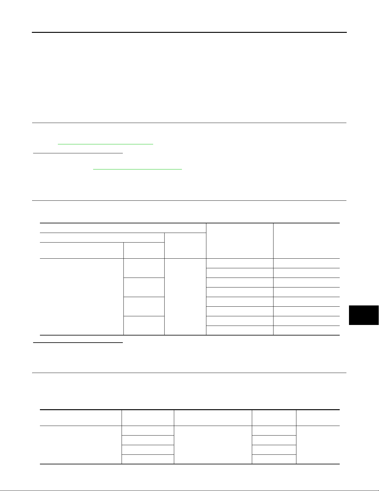
2. Check voltage between automatic drive positioner control unit connector and ground.
Automatic drive positioner control
unit connector
Is the inspection result normal?
YES >> GO TO 6.
NO >> GO TO 2.
2.CHECK HARNESS CONTINUITY
CONSULT-III Function".
Diagnosis Procedure".
Terminals
(+)
M51
Terminal
3
4
19
20
(–)
Ground
Mirror switch
Condition
UP 0
Other than above 5
LEFT 0
Other than above 5
DOWN 0
Other than above 5
RIGHT 0
Other than above 5
Voltage (V)
(Approx.)
A
B
C
D
E
F
G
H
I
J
K
MIR
M
N
1. Turn ignition switch OFF.
2. Disconnect automatic drive positioner control unit and door mirror remote control switch connector.
3. Check continuity between automatic drive positioner control unit connector and door mirror remote control
switch connector.
Automatic drive positioner control
4. Check continuity between automatic drive positioner control unit connector and ground.
unit connector
M51
O
Terminal
3
413
19 12
20 4
Door mirror remote control
switch connector
D7
Terminal Continuity
15
Existed
P
MIR-11
Page 12
< COMPONENT DIAGNOSIS >
Revision: October 2006
2007 G35 Sedan
MIRROR SWITCH
[WITH ADP]
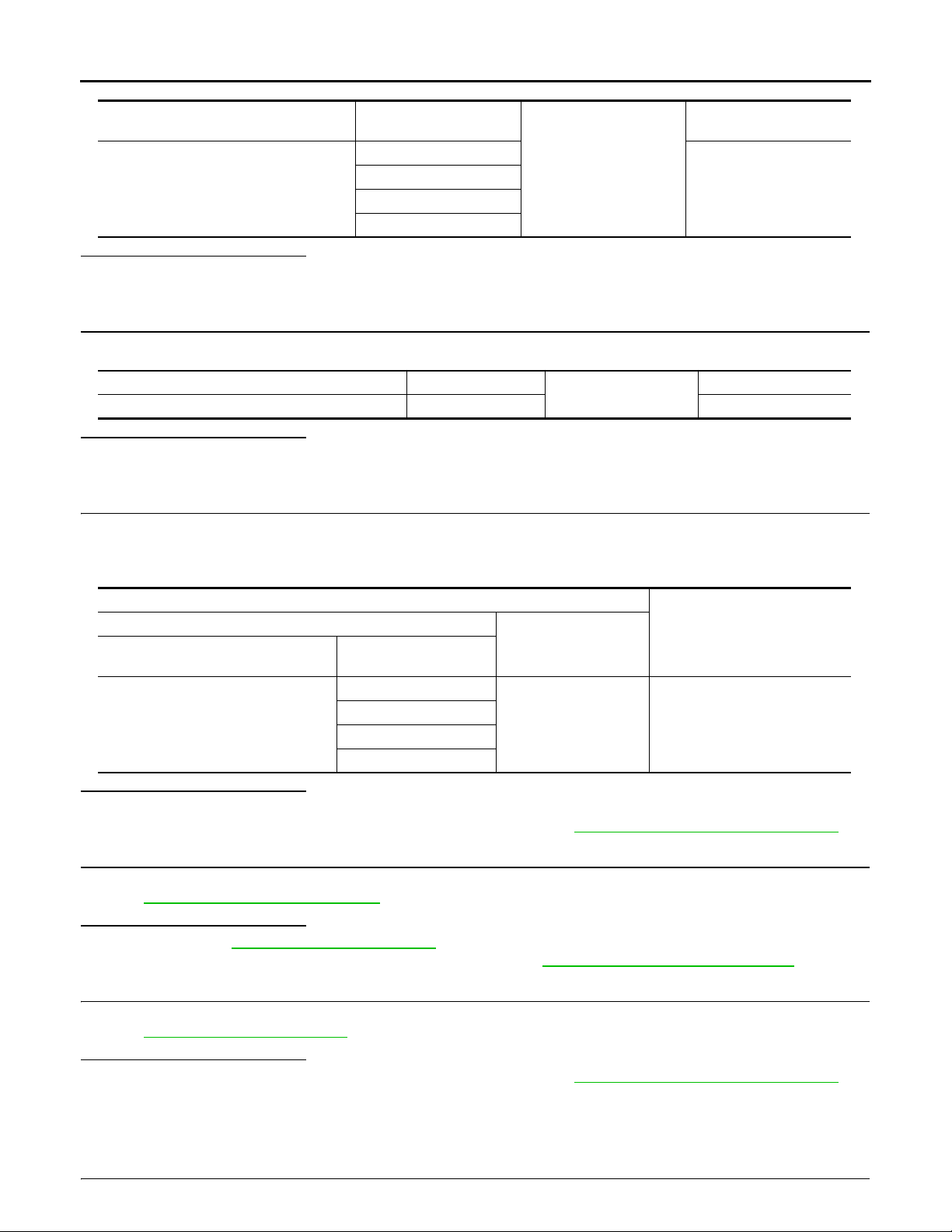
Automatic drive positioner control unit
connector
M51
Terminal
3
4
19
20
Ground
Is the inspection result normal?
YES >> GO TO 3.
NO >> Repair or replace harness.
3.CHECK DOOR MIRROR REMOTE CONTROL SWITCH GROUND CIRCUIT
Check continuity between door mirror remote control switch connector and ground.
Door mirror remote control switch connector Terminal
D7 7 Existed
Ground
Is the inspection result normal?
YES >> GO TO 4.
NO >> Repair or replace harness.
4.CHECK AUTOMATIC DRIVE POSITIONER CONTROL UNIT OUTPUT SIGNAL
1. Connect automatic drive positioner control unit connector.
2. Turn ignition switch ON.
3. Check voltage between automatic drive positioner control unit and ground.
Continuity
Not existed
Continuity
Terminals
(+)
Automatic drive positioner control unit
connector
M51
Terminal
3
4
19
20
(-)
Ground 5
Voltage (V)
(Approx.)
Is the inspection result normal?
YES >> GO TO 5.
NO >> Replace automatic drive positioner control unit. Refer to ADP-218, "
Removal and Installation".
5.CHECK MIRROR SWITCH
Check mirror switch
Refer to MIR-12, "
Component Inspection".
Is the inspection result normal?
YES >> Refer to GI-39, "Intermittent Incident".
NO >> Replace door mirror remote control switch. Refer to MIR-68, "
Removal and Installation".
6.CHECK INTERMITTENT INCIDENT
Check intermittent incident.
Refer to GI-39, "
Is the inspection result normal?
YES >> Replace automatic drive positioner control unit. Refer to ADP-218, "Removal and Installation".
NO >> Repair or replace the malfunctioning parts.
Intermittent Incident".
Component Inspection INFOID:0000000000962319
1.CHECK MIRROR SWITCH
MIR-12
Page 13
MIRROR SWITCH
Revision: October 2006
2007 G35 Sedan
< COMPONENT DIAGNOSIS >
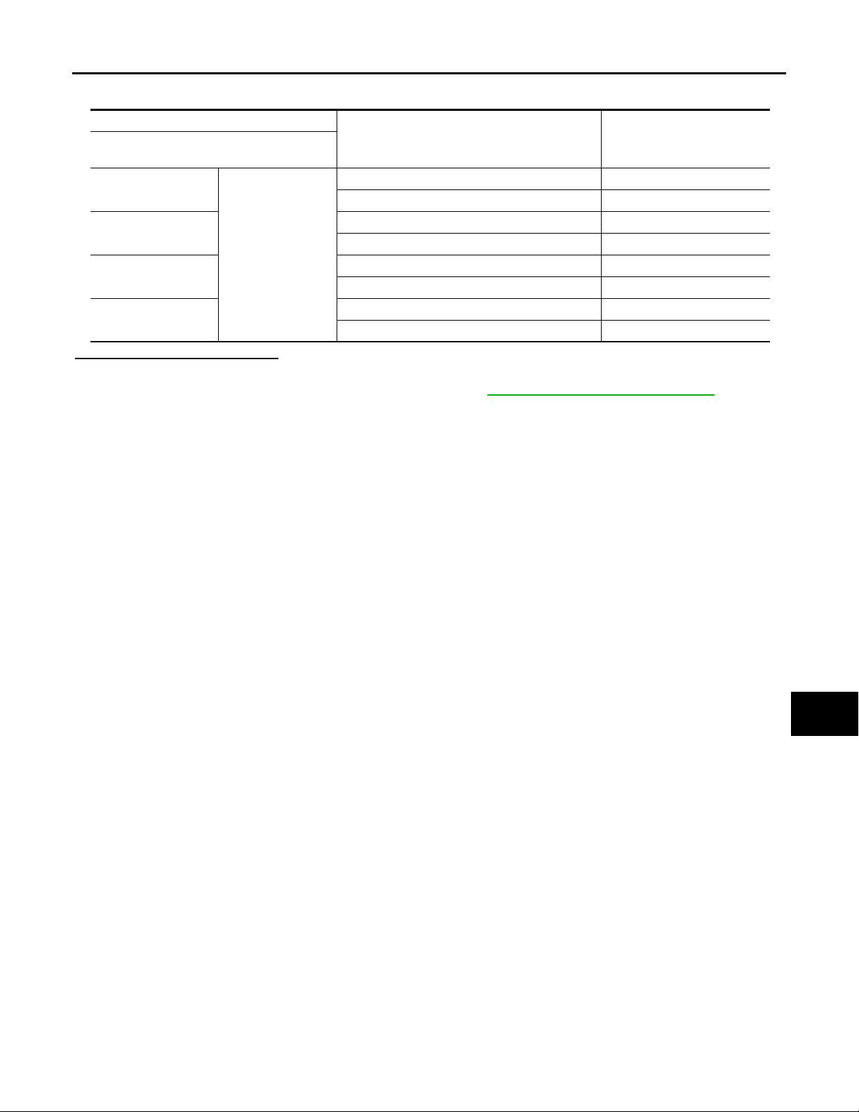
Check door mirror remote control switch.
Terminal
Door mirror remote
control switch
4
13
7
15
12
RIGHT Existed
Other than above Not existed
LEFT Existed
Other than above Not existed
UP Existed
Other than above Not existed
DOWN Existed
Other than above Not existed
Is the inspection result normal?
YES >> INSPECTION END.
NO >> Replace door mirror remote control switch.Refer to MIR-68, "
Mirror switch condition Continuity
[WITH ADP]
Removal and Installation".
A
B
C
D
E
F
G
H
I
J
K
MIR
M
N
O
P
MIR-13
Page 14
CHANGE OVER SWITCH
Revision: October 2006
2007 G35 Sedan
< COMPONENT DIAGNOSIS >
[WITH ADP]
CHANGE OVER SWITCH
Description INFOID:0000000000962320
Changeover switch is integrated into door mirror remote control switch.
Changeover switch has three positions (L, N and R).
It changes door mirror motor operation by transmitting control signal to automatic drive positioner control unit.
Component Function Check INFOID:0000000000962321
1.CHECK CHANGEOVER SWITCH FUNCTION
Check the operation on “MIR CHNG SW-R” or “MIR CHNG SW-L” in “DATA MONITOR” mode with CONSULT-III.
Refer to ADP-48, "
CONSULT-III Function".
Is the inspection result normal?
YES >> Changeover switch function is OK.
NO >> Refer to MIR-14, "
Diagnosis Procedure".
Diagnosis Procedure INFOID:0000000000962322
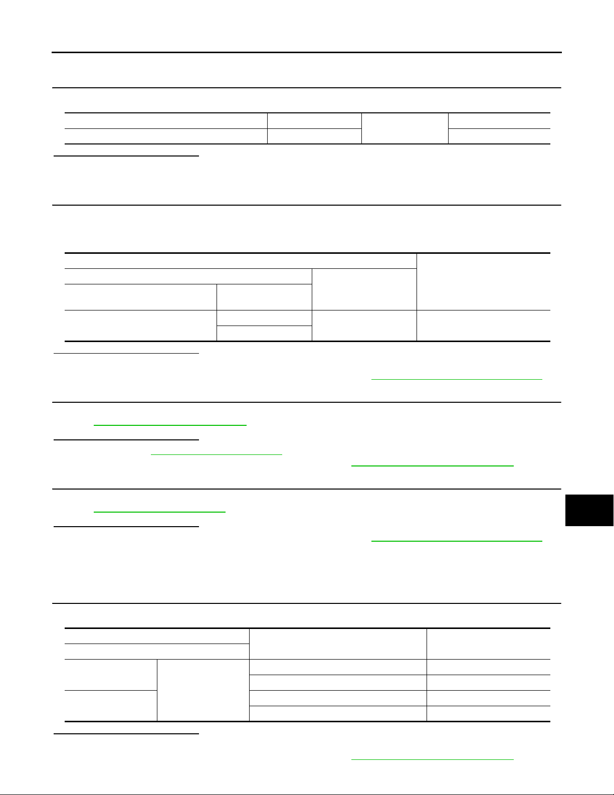
1.CHECK CHANGEOVER SWITCH SIGNAL
1. Turn ignition switch ON.
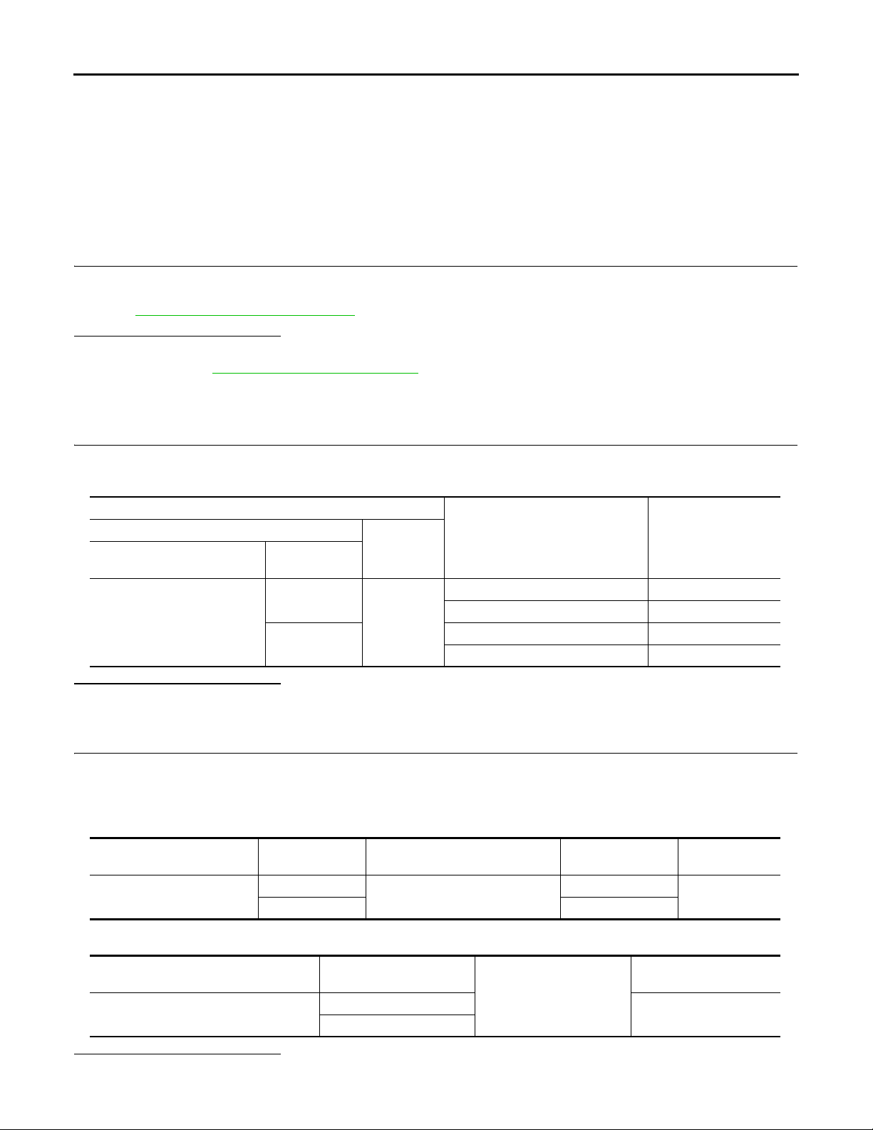
2. Check voltage between automatic drive positioner control unit connector and ground.
Terminals
(+)
Automatic drive positioner
control unit connector
M51
Terminal
2
18
(-)
Ground
Change over switch condition
RIGHT 0
Other than above 5
LEFT 0
Other than above 5
Voltage (V)
(Approx.)
Is the inspection result normal?
YES >> GO TO 6.
NO >> GO TO 2.
2.CHECK HARNESS CONTINUITY
1. Turn ignition switch OFF.
2. Disconnect automatic drive positioner control unit and door mirror remote control switch connector.
3. Check continuity between automatic drive positioner control unit connector and door mirror remote control
switch connector.
Automatic drive positioner
control unit connector
M51
Terminal
2
18 10
4. Check continuity between automatic drive positioner control unit connector and ground.
Door mirror remote control switch
connector
D7
Terminal Continuity
11
Existed
Automatic drive positioner control unit
Is the inspection result normal?
YES >> GO TO 3.
connector
M51
Terminal
2
18
MIR-14
Continuity
Ground
Not existed
Page 15
CHANGE OVER SWITCH
Revision: October 2006
2007 G35 Sedan
< COMPONENT DIAGNOSIS >
NO >> Repair or replace harness.
3.CHECK DOOR MIRROR REMOTE CONTROL SWITCH GROUND CIRCUIT
Check continuity between door mirror remote control switch connector and ground.
[WITH ADP]
A
Door mirror remote control switch connector Terminal
D7 7 Existed
Ground
Is the inspection result normal?
YES >> GO TO 4.
NO >> Repair or replace harness.
4.CHECK AUTOMATIC DRIVE POSITIONER CONTROL UNIT OUTPUT SIGNAL
1. Connect automatic drive positioner control unit connector.
2. Turn ignition switch ON.
3. Check voltage between automatic drive positioner control unit connector and ground.
Terminals
(+)
Automatic drive positioner control unit
connector
M51
Terminal
2
18
(-)
Ground 5
Is the inspection result normal?
YES >> GO TO 5.
NO >> Replace automatic drive positioner control unit. Refer to ADP-218, "
Removal and Installation".
5.CHECK CHANGEOVER SWITCH
Continuity
Voltage (V)
(Approx.)
B
C
D
E
F
G
H
I
Check changeover switch.
Refer to MIR-15, "
Component Inspection".
Is the inspection result normal?
YES >> Refer to GI-39, "Intermittent Incident".
NO >> Replace door mirror remote control switch. Refer to MIR-68, "
Removal and Installation".
6.CHECK INTERMITTENT INCIDENT
Check intermittent incident.
Refer to GI-39, "
Intermittent Incident".
Is the inspection result normal?
YES >> Replace automatic drive positioner control unit. Refer to ADP-218, "Removal and Installation".
NO >> Repair or replace the malfunctioning parts.
Component Inspection INFOID:0000000000962323
1.CHECK CHANGEOVER SWITCH
Check door mirror remote control switch.
Terminal
Door mirror remote control switch
10
7
11
Is the inspection result normal?
YES >> INSPECTION END.
NO >> Replace door mirror remote control switch. Refer to MIR-68, "
Change over switch condition Continuity
LEFT Existed
Other than above Not existed
RIGHT Existed
Other than above Not existed
Removal and Installation".
J
K
MIR
M
N
O
P
MIR-15
Page 16
DOOR MIRROR MOTOR
Revision: October 2006
2007 G35 Sedan
< COMPONENT DIAGNOSIS >
[WITH ADP]
DOOR MIRROR MOTOR
Description INFOID:0000000000962324
It makes mirror face operate from side to side and up and down with the electric power that AUTOMATIC
DRIVE POSITIONER CONTROL UNIT supplies.
Component Function Check INFOID:0000000000962325
1.CHECK DOOR MIRROR MOTOR FUNCTION
Check the operation with “MIRROR MOTOR RH” and “MIRROR MOTOR LH” in “ACTIVE TEST” mode with
CONSULT-III
Refer to ADP-48, "
CONSULT-III Function".
Is the inspection result normal?
YES >> Door mirror motor function is OK.
NO >> Refer to MIR-16, "
Diagnosis Procedure".
Diagnosis Procedure INFOID:0000000000962326
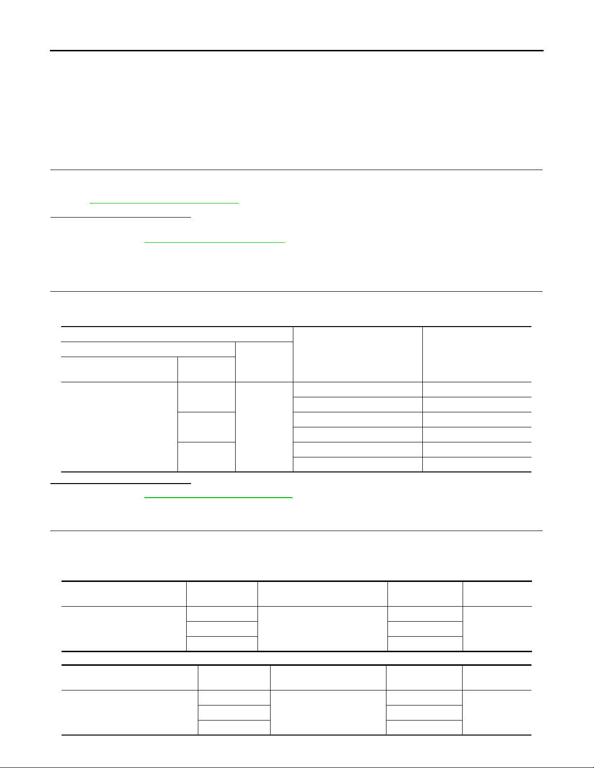
1.CHECK DOOR MIRROR MOTOR INPUT SIGNAL
1. Turn ignition switch ON.
2. Check voltage between door mirror connector and ground.
Terminals
(+)
Door mirror
connector
D3 (Driver side)
D33 (Passenger side)
Terminal
5
6
7
(–)
Ground
Door mirror remote control switch
condition
UP Battery voltage
Other than above 0
LEFT Battery voltage
Other than above 0
DOWN / RIGHT Battery voltage
Other than above 0
Voltage (V)
(Approx.)
Is the inspection result normal?
YES >> Refer to MIR-18, "Component Inspection".
NO >> GO TO 2.
2.CHECK HARNESS CONTINUITY
1. Turn ignition switch OFF.
2. Disconnect automatic drive positioner control unit connector and door mirror connector.
3. Check continuity between automatic drive positioner control unit connector and door mirror connector.
[Door mirror driver side]
Automatic drive positioner con-
trol unit connector
M51
Terminal
16
32 6
Door mirror (driver side) connec-
tor
D3
Terminal Continuity
7
Existed31 5
[Door mirror passenger side]
Automatic drive positioner control
unit connector
M51
Terminal
14
30 7
Door mirror (passenger side)
connector
D33
MIR-16
Terminal Continuity
5
Existed15 6
Page 17
DOOR MIRROR MOTOR
Revision: October 2006
2007 G35 Sedan
< COMPONENT DIAGNOSIS >
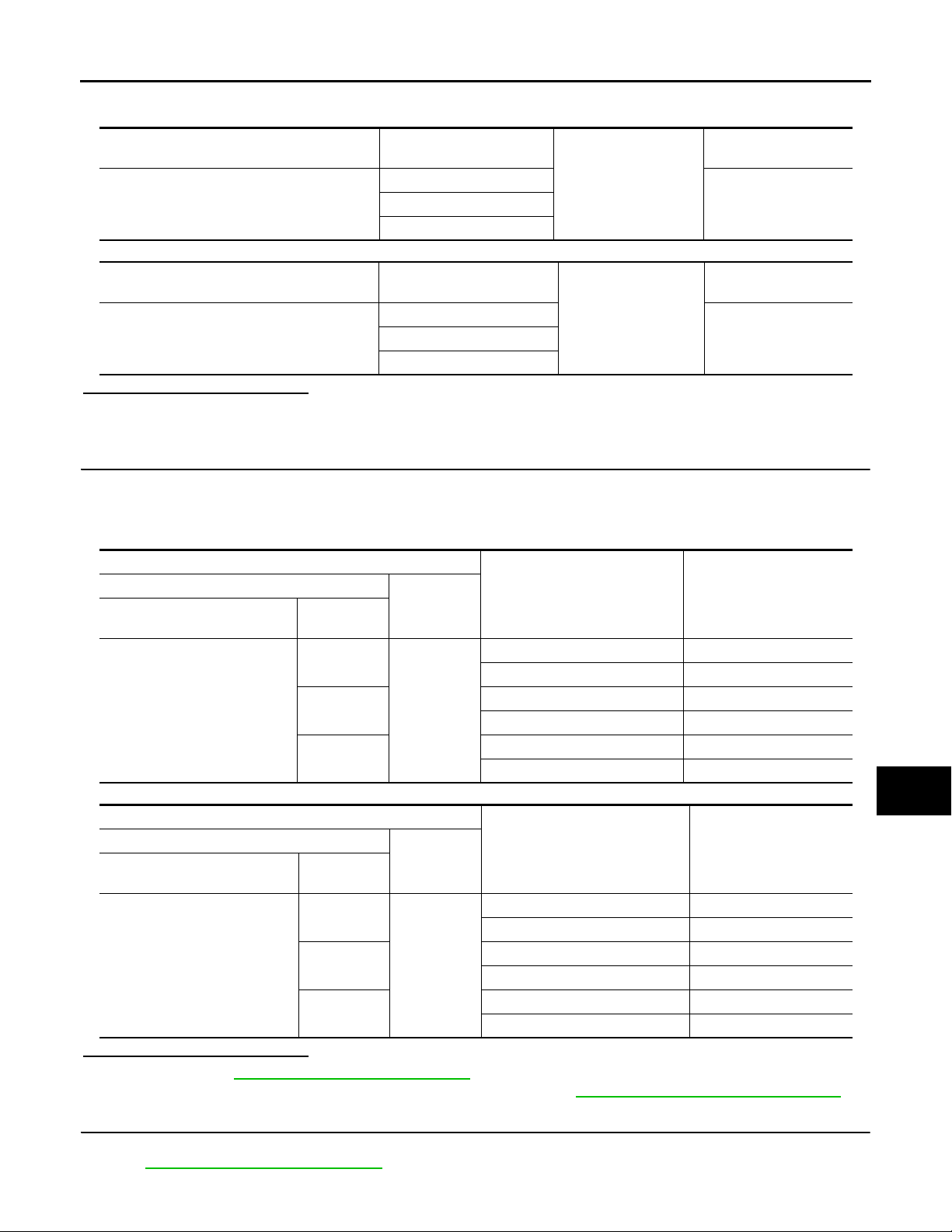
4. Check continuity between automatic drive positioner control unit connector and ground.
[Door mirror driver side]
Automatic drive positioner control unit connec-
tor
M51
[Door mirror passenger side]
Automatic drive positioner control unit connec-
tor
M51
Terminal
16
32
Terminal
14
30
Ground
Ground
Is the inspection result normal?
YES >> GO TO 3.
NO >> Repair or replace harness.
3.CHECK AUTOMATIC DRIVE POSITIONER CONTROL UNIT OUTPUT SIGNAL
[WITH ADP]
A
Continuity
B
Not existed31
C
Continuity
D
Not existed15
E
F
1. Connect automatic drive positioner control unit connector.
2. Turn ignition switch ON.
3. Check voltage between automatic drive positioner control unit connector and ground.
[Door mirror driver side]
Terminals
(+)
Automatic drive positioner con-
trol unit connector
M51
[Door mirror passenger side]
Terminals
(+)
Automatic drive positioner con-
trol unit connector
M51
Terminal
16
31
32
Terminal
14
15
30
(-)
Ground
(-)
Ground
Mirror switch condition
DOWN / RIGHT Battery voltage
Other than above 0
UP Battery voltage
Other than above 0
LEFT Battery voltage
Other than above 0
Mirror switch condition
UP Battery voltage
Other than above 0
LEFT Battery voltage
Other than above 0
DOWN / RIGHT Battery voltage
Other than above 0
Is the inspection result normal?
YES >> Refer to MIR-18, "Component Inspection".
NO >> Replace automatic drive positioner control unit. Refer to ADP-218, "
Removal and Installation".
4.CHECK DOOR MIRROR MOTOR
Voltage (V)
(Approx.)
Voltage (V)
(Approx.)
G
H
I
J
K
MIR
M
N
O
P
Check door mirror motor.
Refer to MIR-18, "
Component Inspection".
MIR-17
Page 18
DOOR MIRROR MOTOR
Revision: October 2006
2007 G35 Sedan
< COMPONENT DIAGNOSIS >
Is the inspection result normal?
YES >> Refer to GI-39, "Intermittent Incident".
NO >> Replace door mirror. Refer to MIR-67, "
Removal and Installation".
[WITH ADP]
Component Inspection INFOID:0000000000962327
1.CHECK DOOR MIRROR MOTOR-I
Check that door mirror motor does not trap foreign objects and does not have any damage.
Refer to MIR-69, "
Is the inspection result normal?
YES >> GO TO 2.
NO >> Replace door mirror.Refer to MIR-67, "
Exploded View".
Removal and Installation".
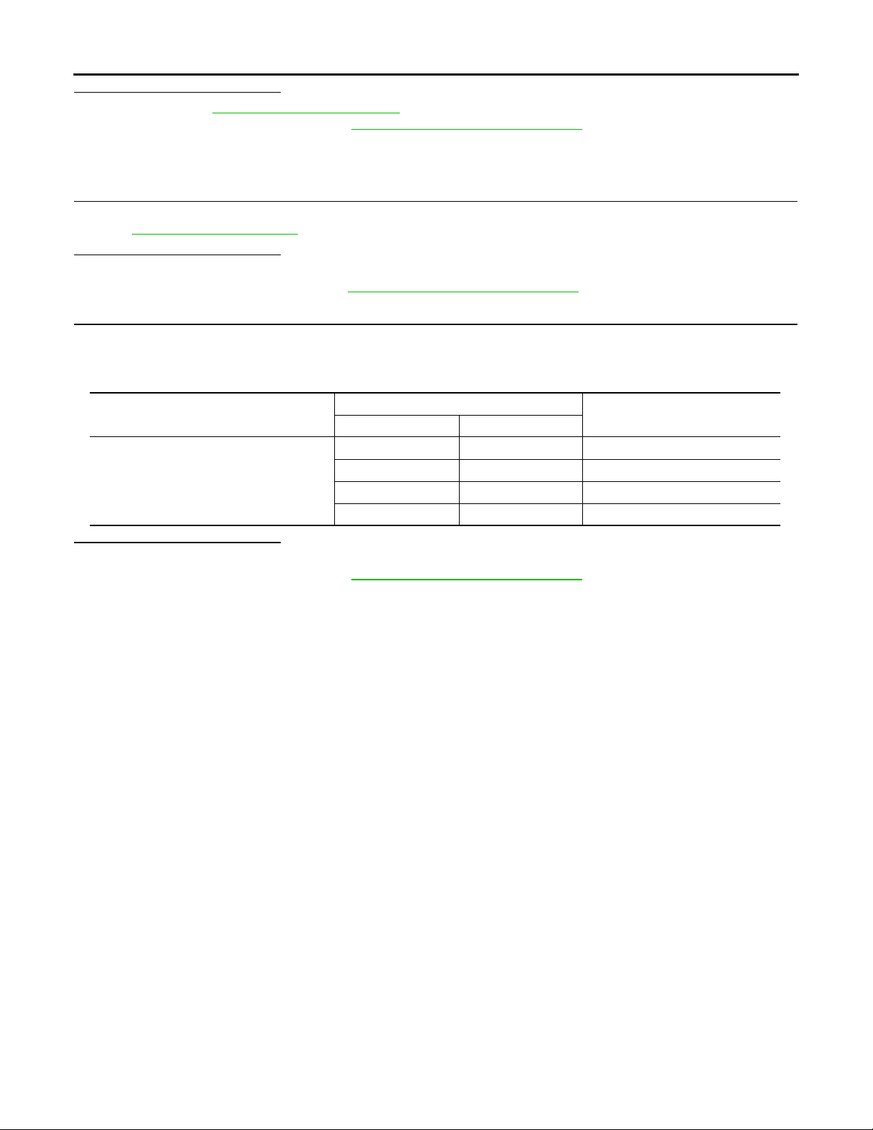
2.CHECK DOOR MIRROR MOTOR-II
1. Turn ignition switch OFF.
2. Disconnect door mirror connector.
3. Apply 12V to each power supply terminal of door mirror motor.
Door mirror connector
D3 (Driver side)
D33 (Passenger side)
Is the inspection result normal?
YES >> INSPECTION END.
NO >> Replace door mirror. Refer to MIR-67, "
Terminal
(+) (–)
76 RIGHT
67 LEFT
57 UP
75 DOWN
Removal and Installation".
Operational direction
MIR-18
Page 19
AUTO ANTI-DAZZLING INSIDE MIRROR CIRCUIT
Revision: October 2006
2007 G35 Sedan
< COMPONENT DIAGNOSIS >
[WITH ADP]
AUTO ANTI-DAZZLING INSIDE MIRROR CIRCUIT
Description INFOID:0000000000962328
It automatically changes according to the brightness of the light that is reflected from the headlight of the vehicle to the rear.
Component Function Check INFOID:0000000000962329
1.CHECK AUTO ANTI-DAZZLING INSIDE MIRROR FUNCTION
Check that glare-proof mirror can operate when mirror sensor is illuminated.
Is the inspection result normal?
YES >> Auto anti-dazzling inside mirror function is OK.
NO >> Refer to MIR-19, "
Diagnosis Procedure".
Diagnosis Procedure INFOID:0000000000962330
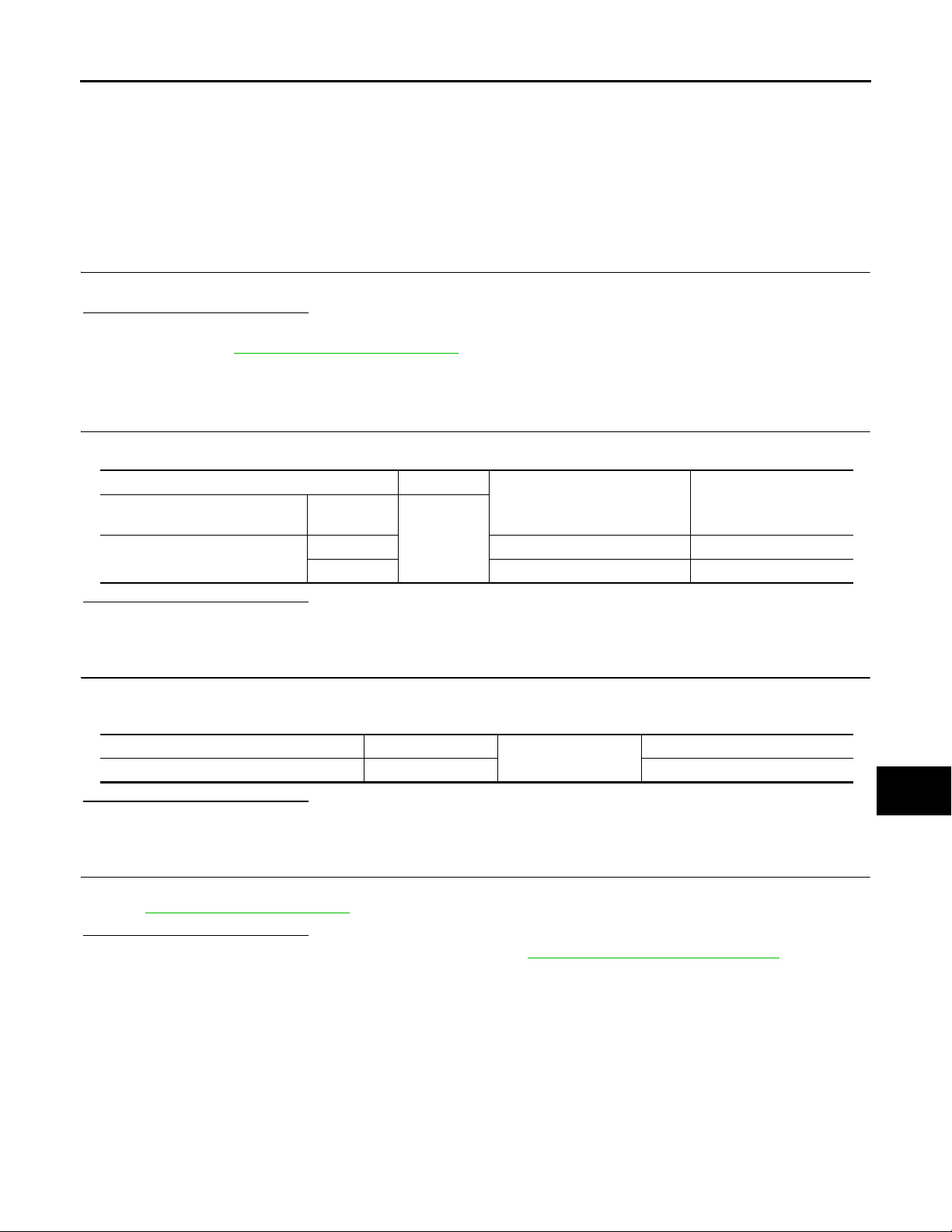
1.CHECK POWER SUPPLY CIRCUIT
Check voltage between auto anti-dazzling inside mirror connector and ground.
(+) (-)
Auto anti-dazzling inside mirror
connector
R3
Is the inspection result normal?
YES >> GO TO 2.
NO >> Repair or replace harness.
Terminal
Condition of ignition switch
6 ON or START Battery voltage
10 OFF Battery voltage
Ground
Voltage (V)
(Approx.)
2.CHECK GROUND CIRCUIT
1. Disconnect auto anti-dazzling inside mirror connector.
2. Check continuity between auto anti-dazzling inside mirror connector and ground.
Auto anti-dazzling inside mirror connector Terminal
R3 8 Existed
Is the inspection result normal?
YES >> GO TO 3.
NO >> Repair or replace harness.
Ground
Continuity
3.CHECK INTERMITTENT INCIDENT
A
B
C
D
E
F
G
H
I
J
K
MIR
M
Check intermittent incident.
Refer to GI-39, "
Is the inspection result normal?
YES >> Replace auto anti-dazzling inside mirror. Refer to MIR-66, "Removal and Installation".
NO >> Repair or replace the malfunctioning parts.
Intermittent Incident".
N
O
P
MIR-19
Page 20
AUTO ANTI-DAZZLING INSIDE MIRROR SYSTEM
B
Revision: October 2006
2007 G35 Sedan
< COMPONENT DIAGNOSIS >
[WITH ADP]
AUTO ANTI-DAZZLING INSIDE MIRROR SYSTEM
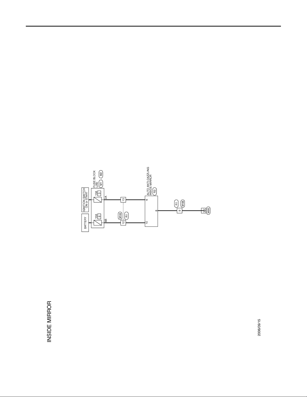
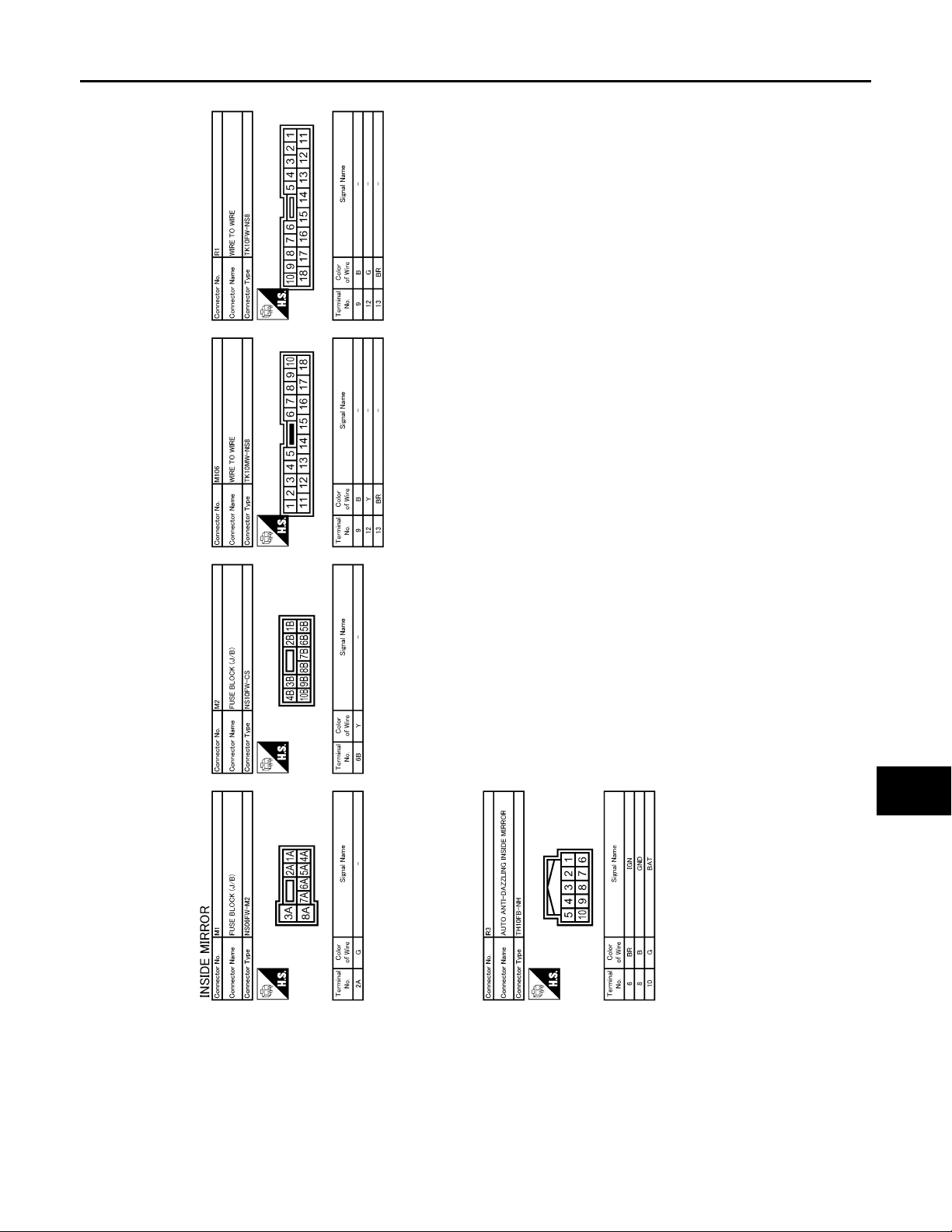
Wiring Diagram — INSIDE MIRROR SYSTEM — INFOID:0000000000962331
JCLWA0004G
MIR-20
Page 21
AUTO ANTI-DAZZLING INSIDE MIRROR SYSTEM
B
Revision: October 2006
2007 G35 Sedan
< COMPONENT DIAGNOSIS >
[WITH ADP]
A
B
C
D
E
F
G
H
I
J
K
MIR
M
N
O
JCLWA0005G
P
MIR-21
Page 22

DRIVER SEAT CONTROL UNIT
Revision: October 2006
2007 G35 Sedan
< ECU DIAGNOSIS >
[WITH ADP]
ECU DIAGNOSIS
DRIVER SEAT CONTROL UNIT
Reference Value INFOID:0000000000962332
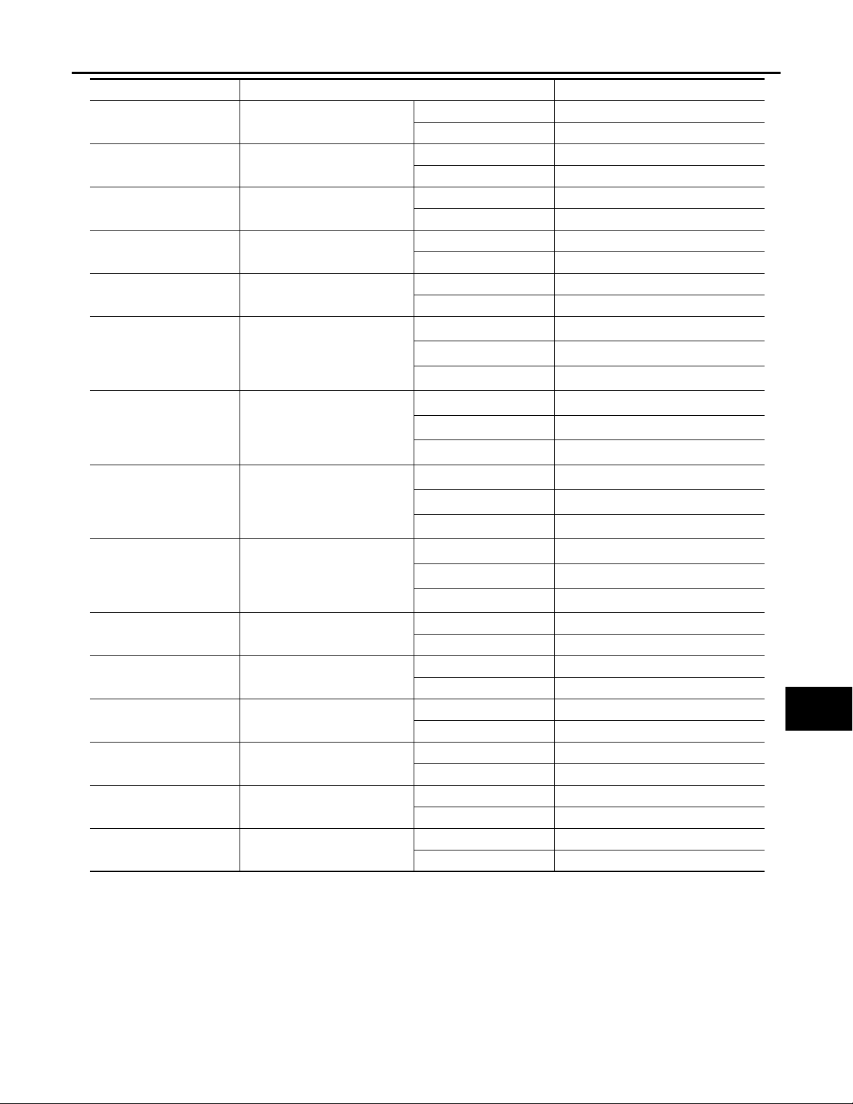
VALUES ON THE DIAGNOSIS TOOL
Monitor Item Condition Val ue/Status
SET SW Set switch
MEMORY SW1 Memory switch 1
MEMORY SW2 Memory switch 2
SLIDE SW–FR Sliding switch (front)
SLIDE SW–RR Sliding switch (rear)
RECLN SW–FR Reclining switch (front)
RECLN SW–RR Reclining switch (rear)
LIFT FR SW–UP Lifting switch front (up)
LIFT FR SW–DN Lifting switch front (down)
LIFT RR SW–UP Lifting switch rear (up)
LIFT RR SW–DN Lifting switch rear (down)
MIR CON SW–UP Mirror switch
MIR CON SW–DN Mirror switch
MIR CON SW–RH Mirror switch
MIR CON SW–LH Mirror switch
MIR CHNG SW–R Changeover switch
MIR CHNG SW–L Changeover switch
TILT SW-UP Tilt switch
TILT SW-DOWN Tilt switch
Push ON
Release OFF
Push ON
Release OFF
Push ON
Release OFF
Operate ON
Release OFF
Operate ON
Release OFF
Operate ON
Release OFF
Operate ON
Release OFF
Operate ON
Release OFF
Operate ON
Release OFF
Operate ON
Release OFF
Operate ON
Release OFF
Up ON
Other than above OFF
Down ON
Other than above OFF
Right ON
Other than above OFF
Left ON
Other than above OFF
Right ON
Other than above OFF
Left ON
Other than above OFF
Up ON
Other than above OFF
Down ON
Other than above OFF
MIR-22
Page 23
< ECU DIAGNOSIS >
Revision: October 2006
2007 G35 Sedan
DRIVER SEAT CONTROL UNIT
[WITH ADP]
Monitor Item Condition Value/Status
TELESCO SW-FR Telescopic switch
TELESCO SW-RR Tilt switch
DETENT SW
PARK BRAKE SW
STARTER SW Ignition position
SLIDE PULSE Seat sliding
RECLN PULSE Seat reclining
LIFT FR PULSE Seat lifter (front)
LIFT RR PULSE Seat lifter (rear)
MIR/SEN RH U–D Door mirror (passenger side)
MIR/SEN RH R–L Door mirror (passenger side)
MIR/SEN LH U–D Door mirror (driver side)
MIR/SEN LH R–L Door mirror (driver side)
TILT SEN Tilt position
TELESCO SEN Telescopic position
*1
: Only for AT model
*2
: Only for MT model
*3
: The value at the position attained when the battery is connected is regarded as 32768.
*1
*2
AT selector lever
Parking brake
Forward ON
Other than above OFF
Backward ON
Other than above OFF
P position OFF
Other than above ON
Applied ON
Release OFF
Cranking ON
Other than above OFF
Forward
Backward
Other than above
Forward
Backward
Other than above
Up
Down
Other than above
Up
Down
Other than above
Close to peak 3.4
Close to valley 0.6
Close to left edge 3.4
Close to right edge 0.6
Close to peak 3.4
Close to valley 0.6
Close to left edge 0.6
Close to right edge 3.4
Top 1.2
Bottom 3.4
Top 3.4
Bottom 0.8
The numeral value decreases
The numeral value increases
No change to numeral value
The numeral value decreases
The numeral value increases
No change to numeral value
The numeral value decreases
The numeral value increases
No change to numeral value
The numeral value decreases
The numeral value increases
No change to numeral value
A
B
C
D
*3
*3
*3
*3
*3
E
F
G
*3
*3
*3
*3
*3
*3
*3
H
I
J
K
MIR
M
N
O
P
MIR-23
Page 24
< ECU DIAGNOSIS >
Revision: October 2006
2007 G35 Sedan
TERMINAL LAYOUT
PHYSICAL VALUES
DRIVER SEAT CONTROL UNIT
[WITH ADP]
JMJIA0199ZZ
Terminal No.
+ - Sign al na me
1GroundL/W
3—R/YCAN-H — — —
*1
Ground LG
8
Ground
9
Wire
color
UART communication
(RX)
Parking brake switch
signal
Reclining sensor sig-
W/G
nal
Description
Input/
Output
Input Ignition switch ON
Input Parking brake
Input Seat reclining
Condition
Voltage (V)
(Approx)
Applied 0
Release Battery voltage
Operate
Stop 0 or 5
JMJIA0118ZZ
JMJIA0119ZZ
10 Ground P/B
11 Ground BR
12 Ground SB
Lifting sensor (rear)
signal
Sliding switch backward signal
Reclining switch backward signal
Input Seat lifting (rear)
Input Sliding switch
Input Reclining switch
MIR-24
Operate
Stop 0 or 5
Operate
(back-
ward)
Release Battery voltage
Operate
(back-
ward)
Release Battery voltage
0
0
JMJIA0119ZZ
Page 25
< ECU DIAGNOSIS >
Revision: October 2006
2007 G35 Sedan
DRIVER SEAT CONTROL UNIT
[WITH ADP]
Terminal No.
+ - Signal name
13 Ground LG/R
14 Ground GB
16 Ground O Sensor power supply Output — 5
17 Ground Y/R
19 — V CAN-L — — —
*2
Ground L/Y Detention switch Input A/T selector lever
21
Wire
color
Lifting switch (front)
down signal
Lifting switch (rear)
down signal
UART communication
(TX)
Description
Input/
Output
Input
Input Lifting switch (rear)
Output Ignition switch ON
Lifting switch
(front)
Condition
Voltage (V)
(Approx)
Operate
(down)
Release Battery voltage
Operate
(down)
Release Battery voltage
P position 0
Except P
position
A
0
0
B
C
D
E
F
JMJIA0121ZZ
G
H
24 Ground R Sliding sensor signal Input Seat sliding
25 Ground Y/B
26 Ground Y
27 Ground R/G
28 Ground W/B
Lifting sensor (front)
signal
Sliding switch forward
signal
Reclining switch forward signal
Lifting switch (front) up
signal
Input Seat lifting (front)
Input Sliding switch
Input Reclining switch
Input
Seat lifting switch
(front)
Operate
Stop 0 or 5
Operate
Stop 0 or 5
Operate
(forward)
Release Battery voltage
Operate
(forward)
Release Battery voltage
Operate
(up)
Release Battery voltage
0
0
0
JMJIA0120ZZ
JMJIA0119ZZ
JMJIA0119ZZ
I
J
K
MIR
M
N
O
P
MIR-25
Page 26

< ECU DIAGNOSIS >
Revision: October 2006
2007 G35 Sedan
DRIVER SEAT CONTROL UNIT
[WITH ADP]
Terminal No.
+ - Sign al na me
29 Ground P/L
31 Ground GR Sensor ground — — 0
32 Ground B/W Ground (signal) — — 0
33 Ground R Power source (C/B) Input — Battery voltage
35 Ground W/R
36 Ground G/Y
37 Ground G/W
38 Ground L/Y
39 Ground R/B
40 Ground R/W Power source (Fuse) Input — Battery voltage
42 Ground W/B
44 Ground P
45 Ground L/R
48 Ground B Ground (power) — — 0
*1
: Only for MT models
*2
: Only for AT models
Wire
color
Lifting switch (rear) up
signal
Sliding motor forward
output signal
Reclining motor forward output signal
Lifting motor (front)
down output signal
Lifting motor (rear) up
output signal
Lifting motor (rear)
down output signal
Sliding motor backward output signal
Reclining motor backward output signal
Lifting motor (front) up
output signal
Description
Input/
Output
Input
Output Seat sliding
Output Seat reclining
Output Seat lifting (front)
Output Seat lifting (rear)
Output Seat lifting (rear)
Output Seat sliding
Output Seat reclining
Output Seat lifting (front)
Seat lifting switch
(rear)
Condition
Operate
(up)
Release Battery voltage
Operate
(forward)
Release 0
Operate
(forward)
Release 0
Operate
(down)
Stop 0
Operate
(up)
Stop 0
Operate
(down)
Stop 0
Operate
(back-
ward)
Stop 0
Operate
(back-
ward)
Stop 0
Operate
(up)
Stop 0
Battery voltage
Battery voltage
Battery voltage
Battery voltage
Battery voltage
Battery voltage
Battery voltage
Battery voltage
Voltage (V)
(Approx)
0
MIR-26
Page 27
DRIVER SEAT CONTROL UNIT
B
Revision: October 2006
2007 G35 Sedan
< ECU DIAGNOSIS >
[WITH ADP]
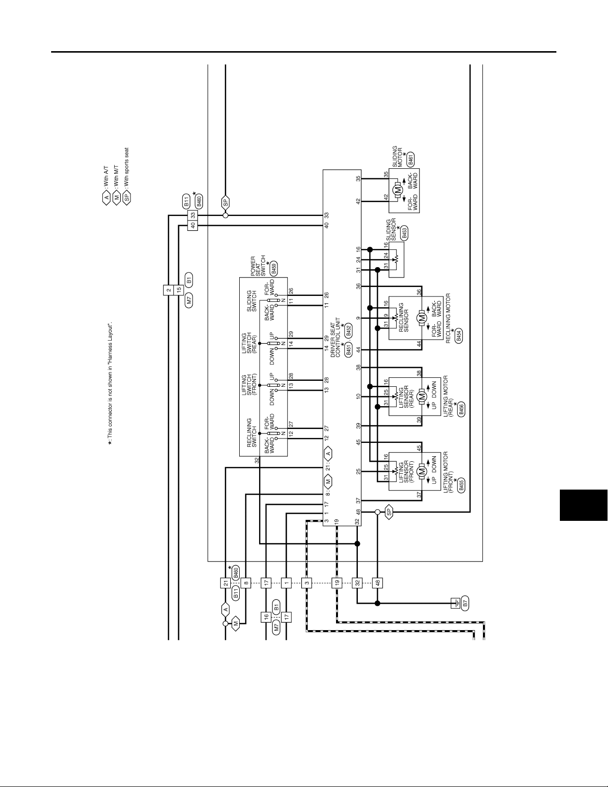
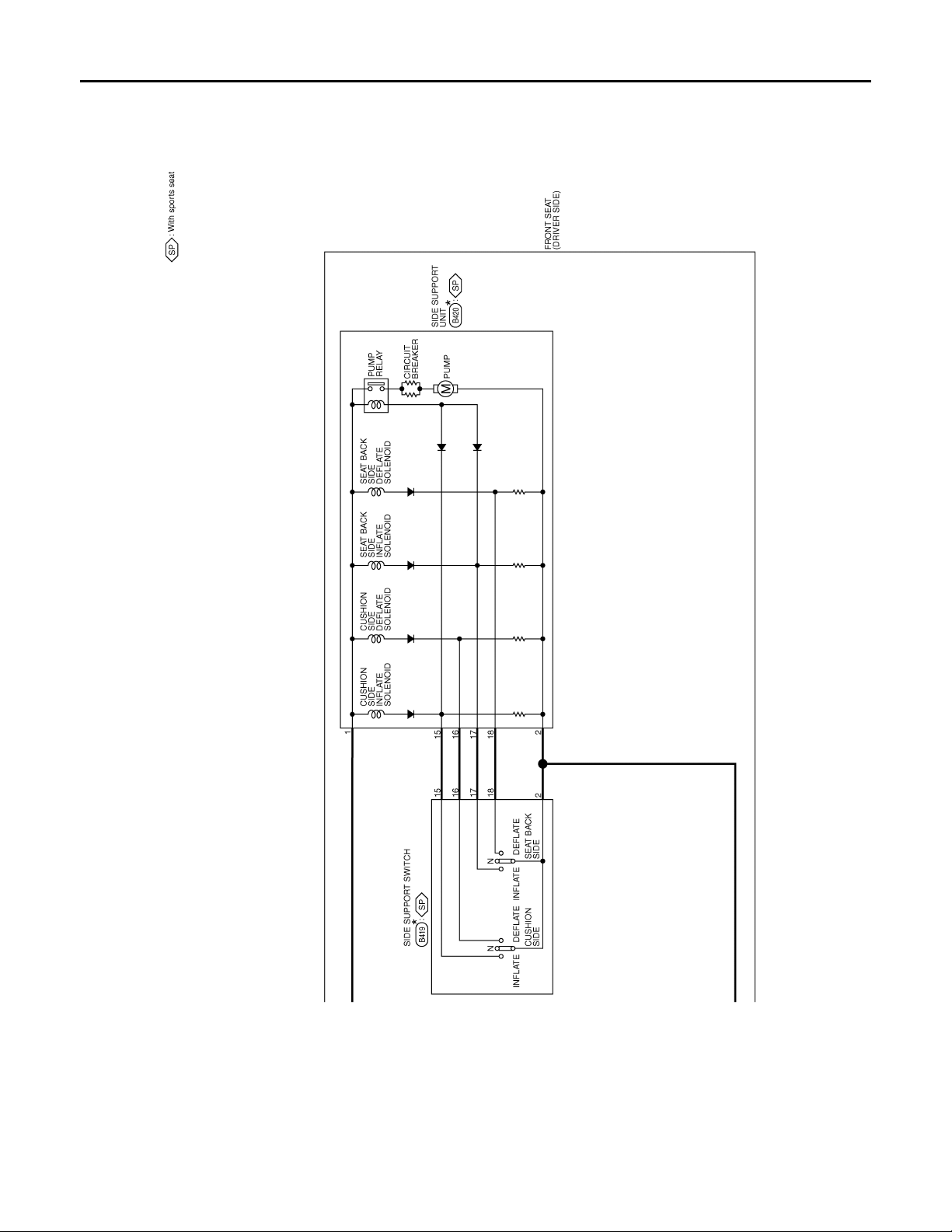
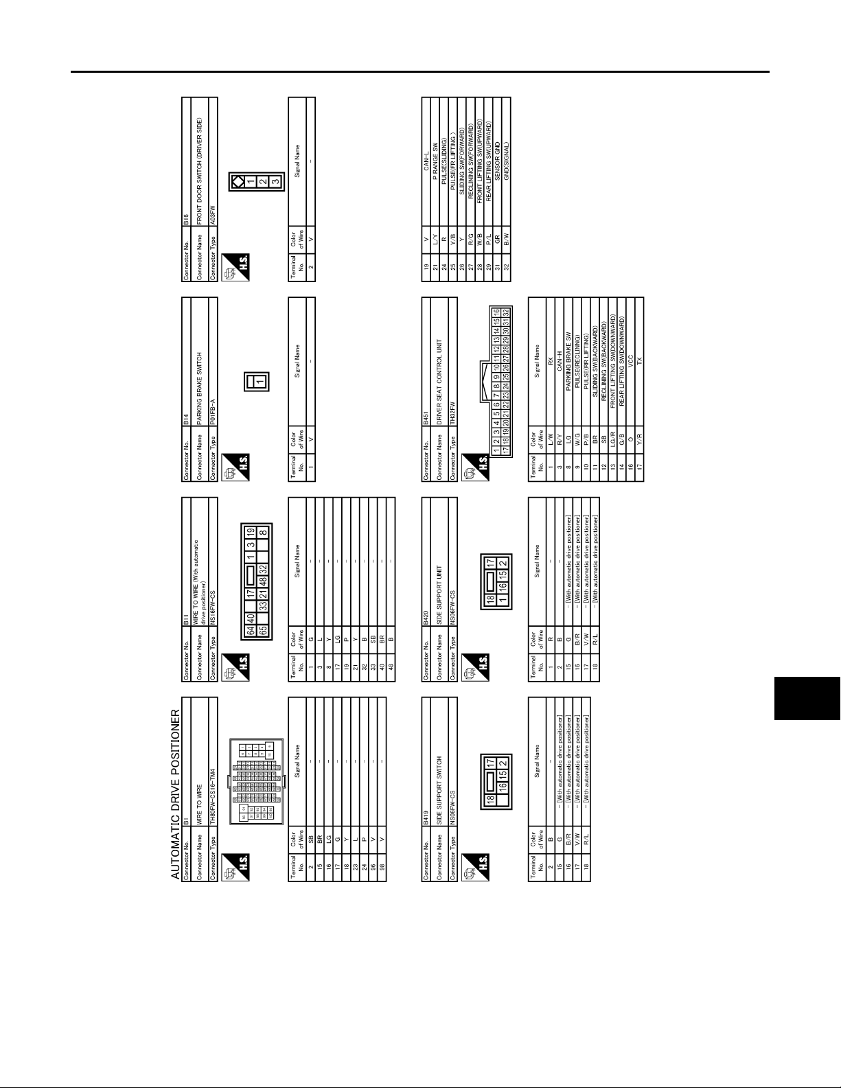
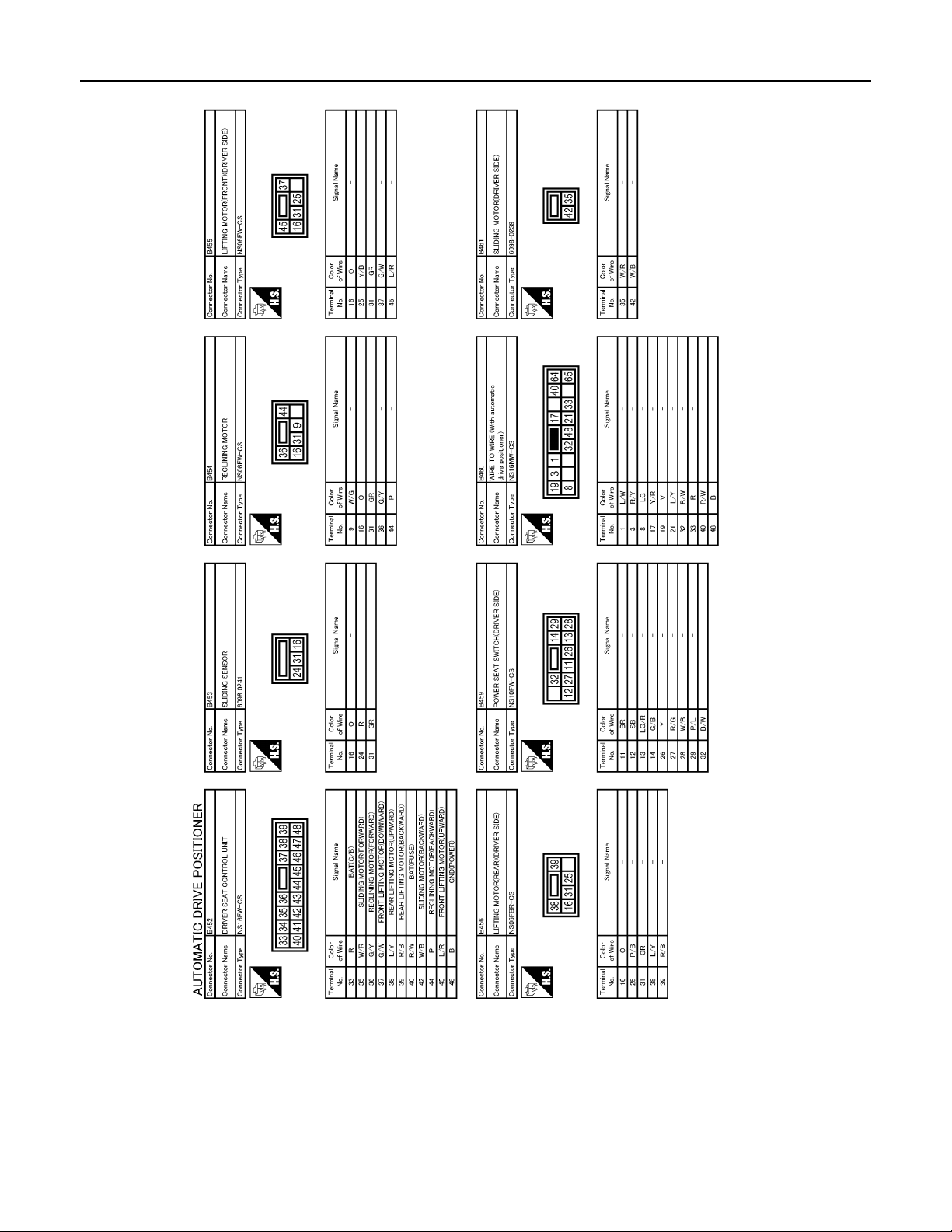
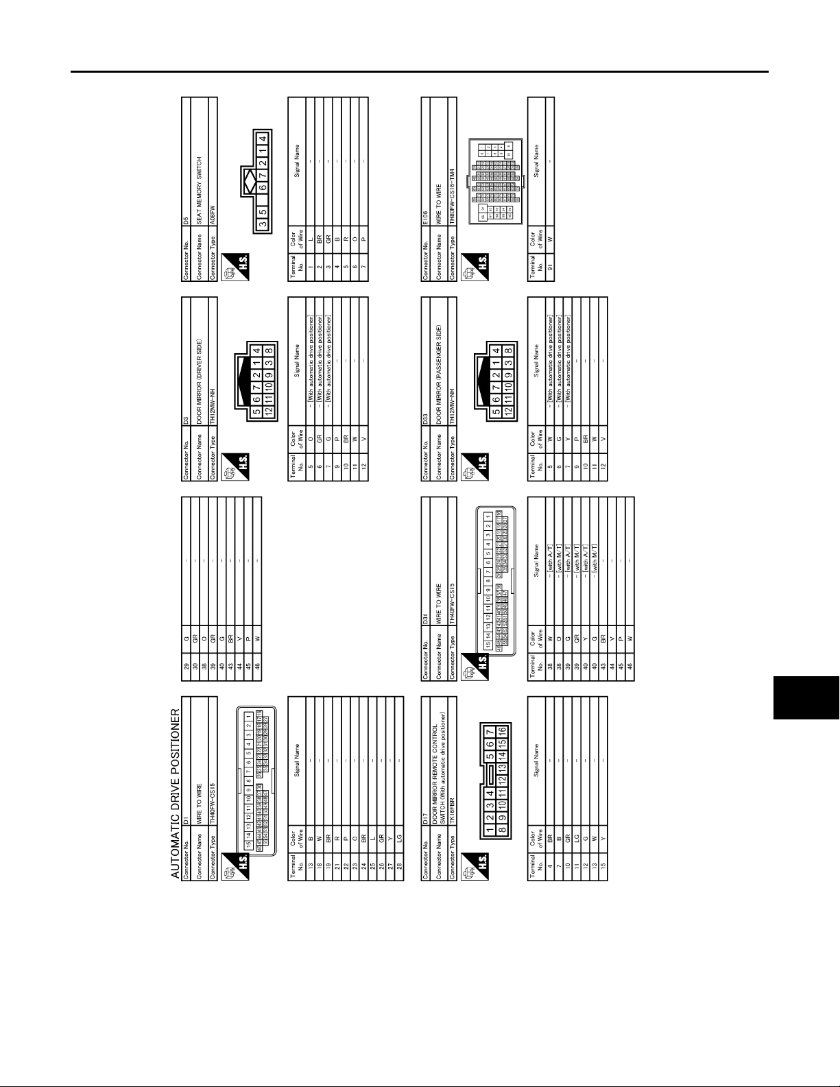
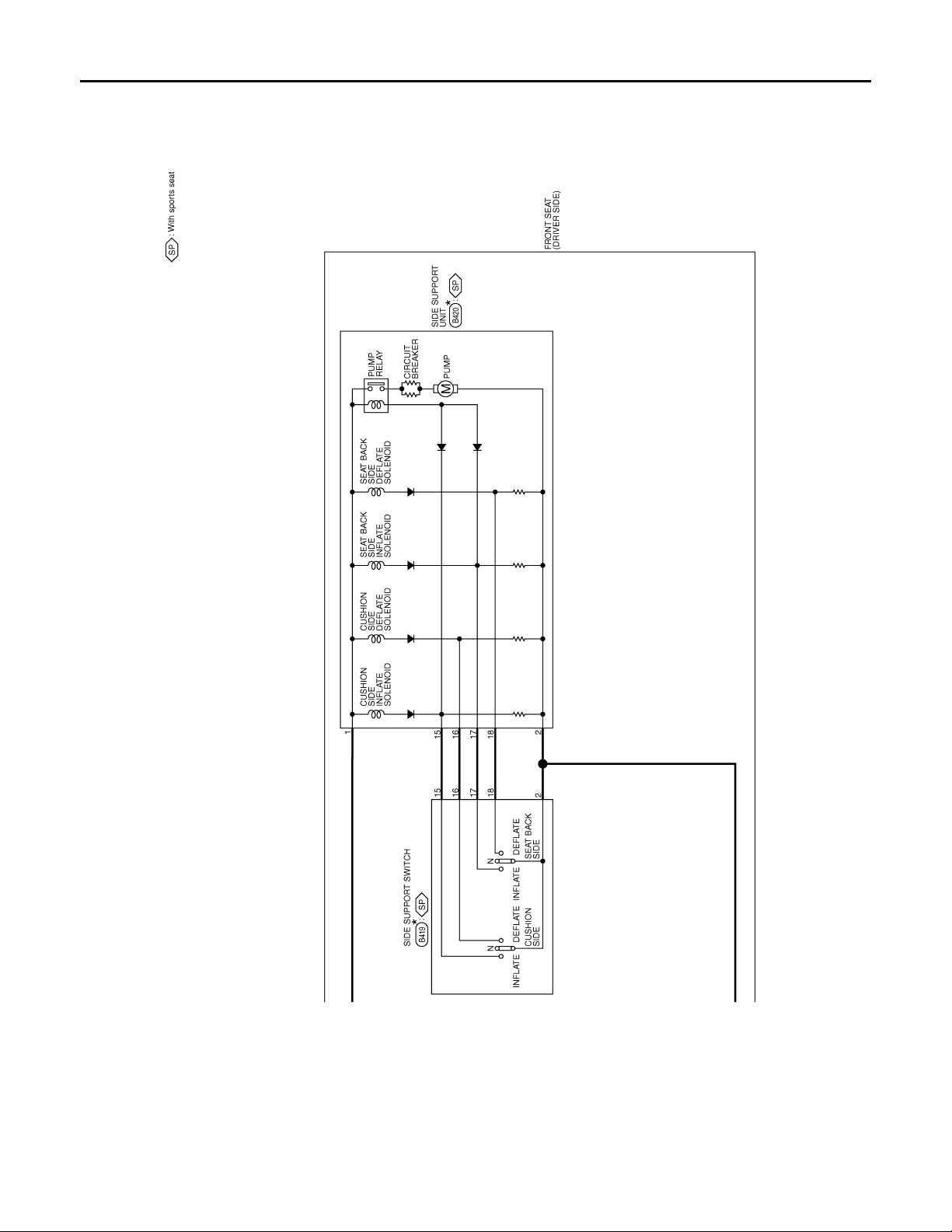
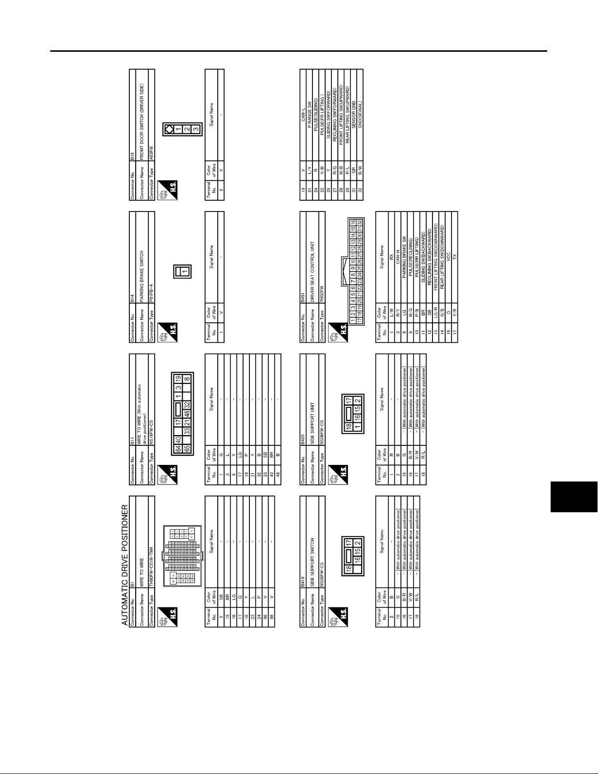
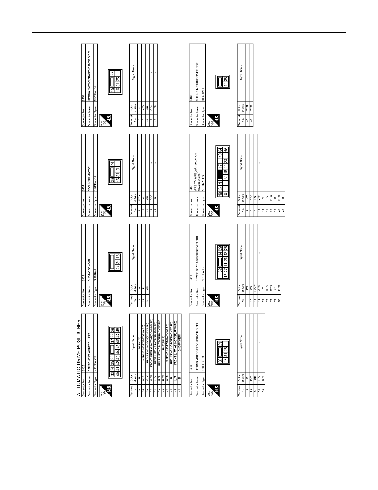
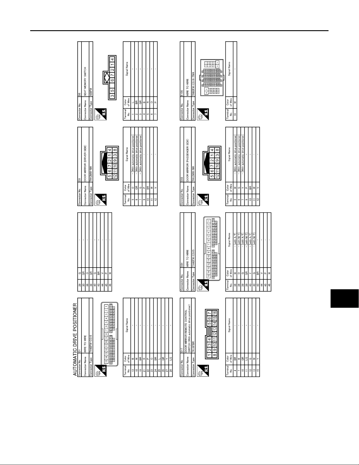
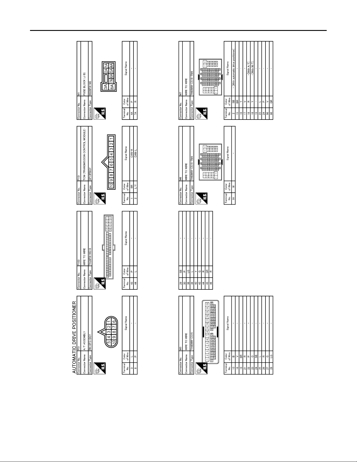
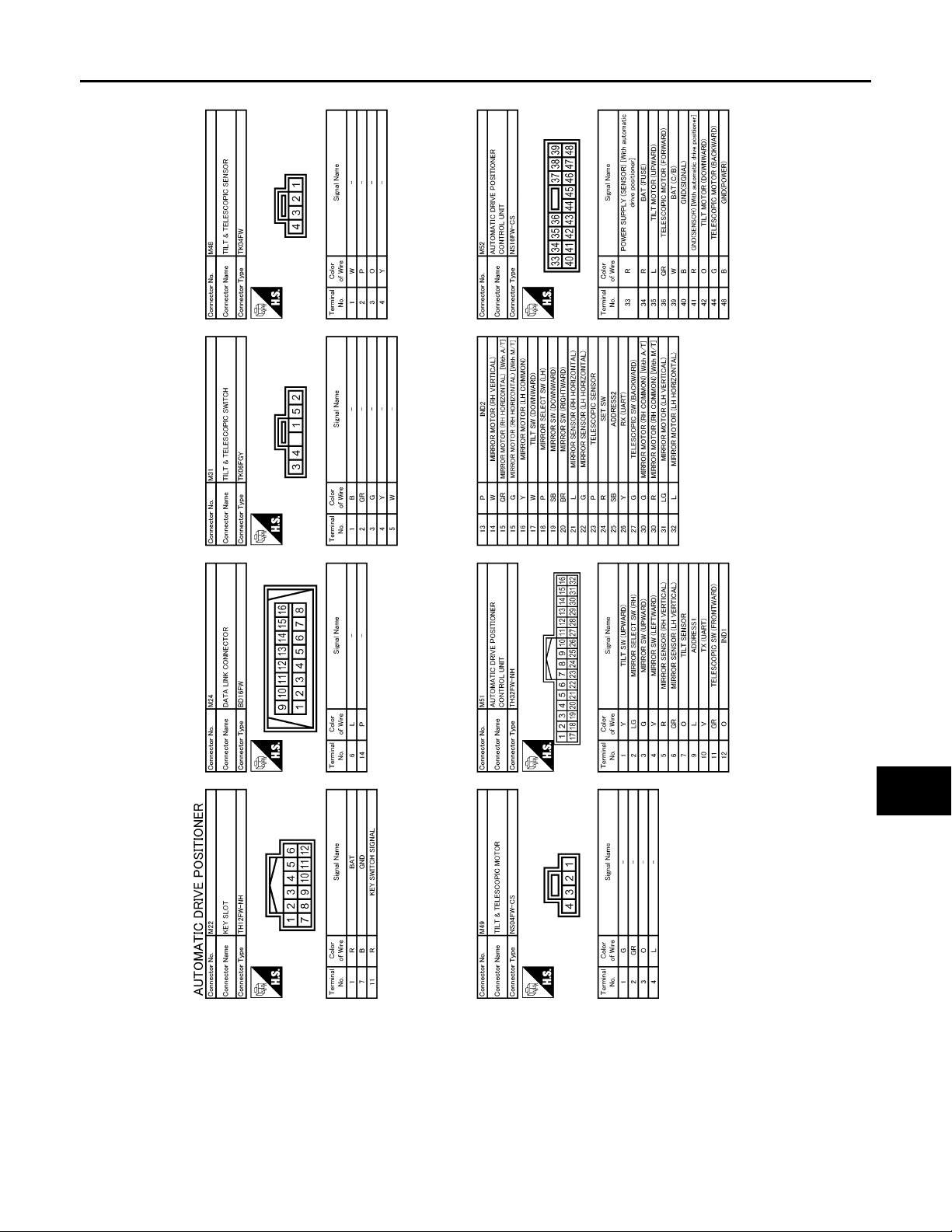
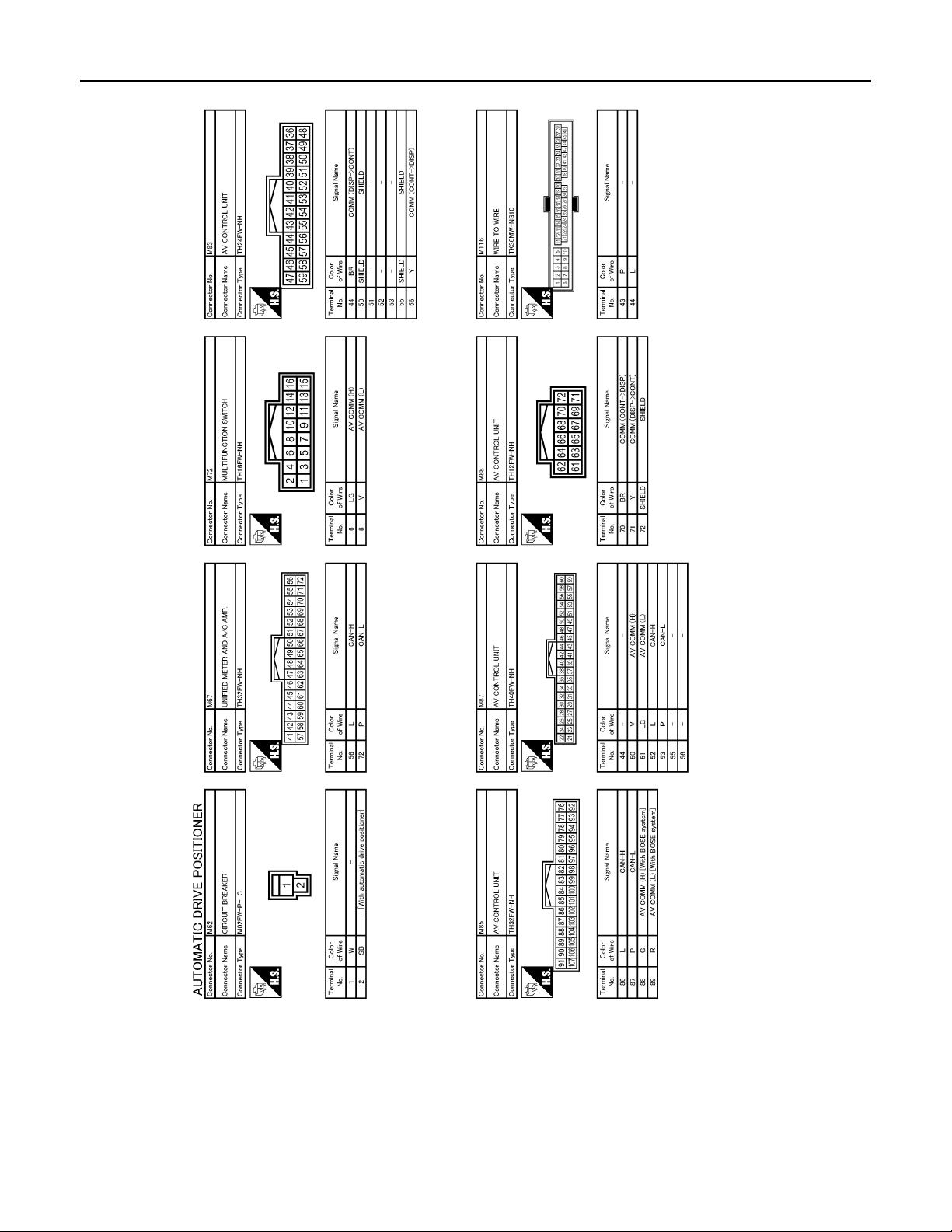
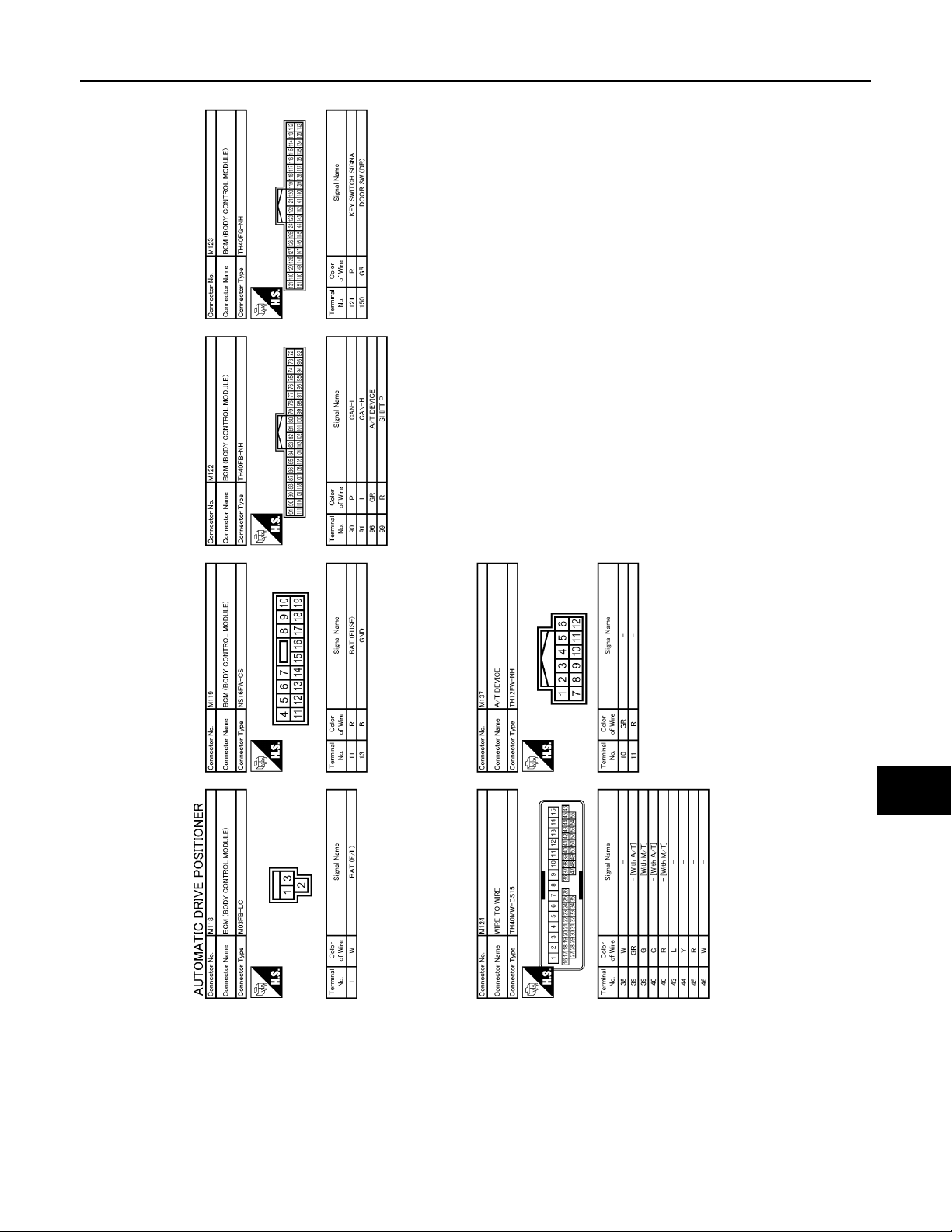
Wiring Diagram—AUTOMATIC DRIVE POSITIONER CONTROL SYSTEM—
INFOID:0000000000962333
A
B
C
D
E
F
G
H
I
J
K
MIR
M
N
O
MIR-27
JCJWA0019G
P
Page 28
< ECU DIAGNOSIS >
B
Revision: October 2006
2007 G35 Sedan
DRIVER SEAT CONTROL UNIT
[WITH ADP]
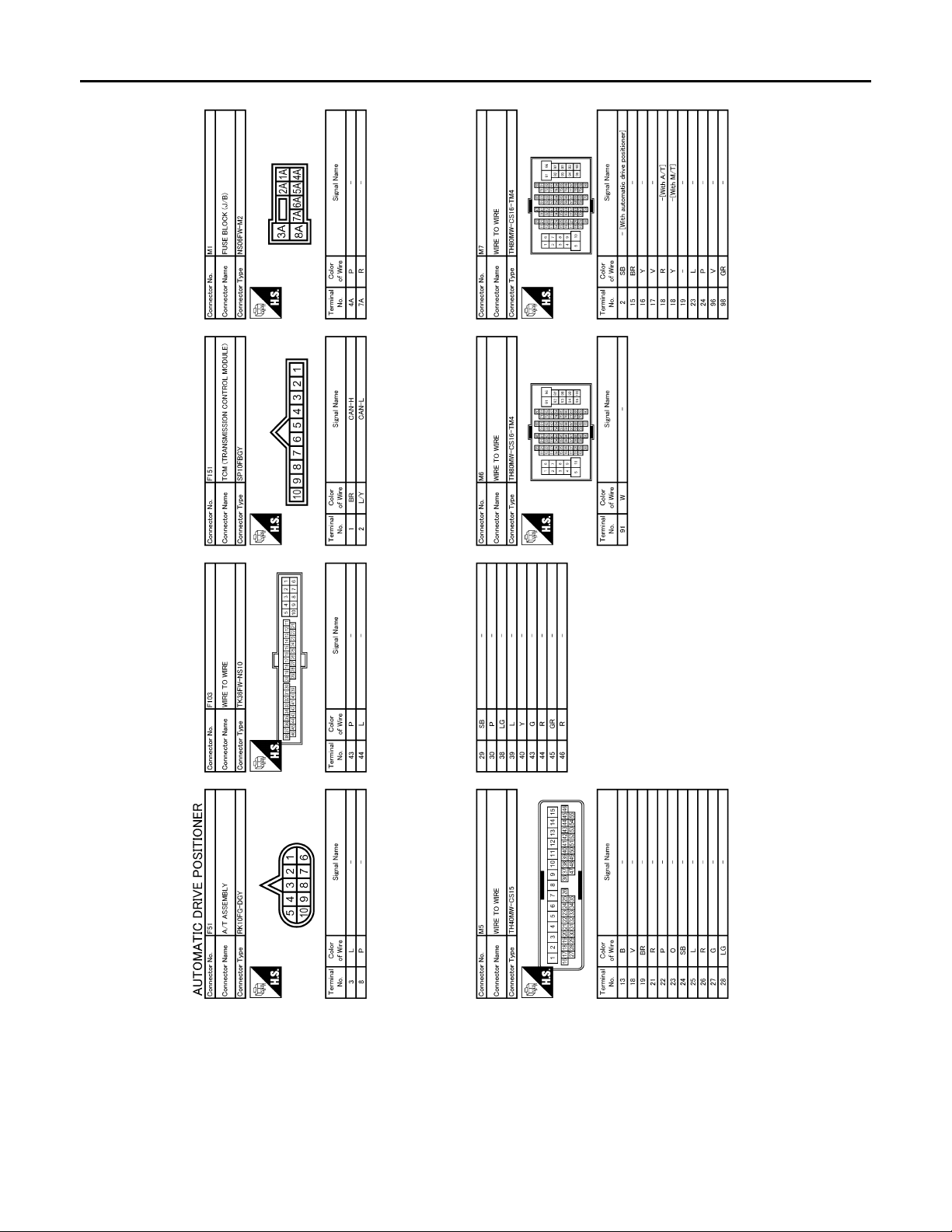
JCJWA0020G
MIR-28
Page 29
< ECU DIAGNOSIS >
B
Revision: October 2006
2007 G35 Sedan
DRIVER SEAT CONTROL UNIT
[WITH ADP]
A
B
C
D
E
F
G
H
I
J
K
MIR
M
N
O
JCJWA0021G
P
MIR-29
Page 30
< ECU DIAGNOSIS >
B
Revision: October 2006
2007 G35 Sedan
DRIVER SEAT CONTROL UNIT
[WITH ADP]
JCJWA0022G
MIR-30
Page 31
< ECU DIAGNOSIS >
B
Revision: October 2006
2007 G35 Sedan
DRIVER SEAT CONTROL UNIT
[WITH ADP]
A
B
C
D
E
F
G
H
I
J
K
MIR
M
N
O
JCJWA0023G
P
MIR-31
Page 32
< ECU DIAGNOSIS >
B
Revision: October 2006
2007 G35 Sedan
DRIVER SEAT CONTROL UNIT
[WITH ADP]
JCJWA0024G
MIR-32
Page 33
< ECU DIAGNOSIS >
B
Revision: October 2006
2007 G35 Sedan
DRIVER SEAT CONTROL UNIT
[WITH ADP]
A
B
C
D
E
F
G
H
I
J
K
MIR
M
N
O
JCJWA0025G
P
MIR-33
Page 34
< ECU DIAGNOSIS >
B
Revision: October 2006
2007 G35 Sedan
DRIVER SEAT CONTROL UNIT
[WITH ADP]
JCJWA0026G
MIR-34
Page 35
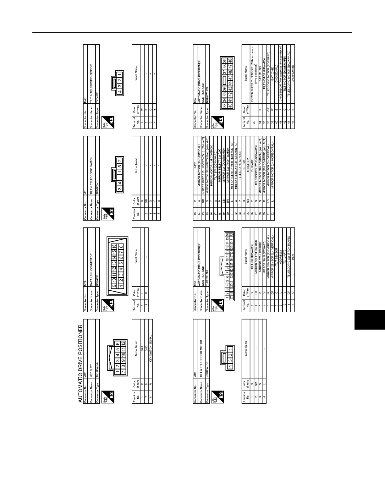
< ECU DIAGNOSIS >
B
Revision: October 2006
2007 G35 Sedan
DRIVER SEAT CONTROL UNIT
[WITH ADP]
A
B
C
D
E
F
G
H
I
J
K
MIR
M
N
O
JCJWA0027G
P
MIR-35
Page 36
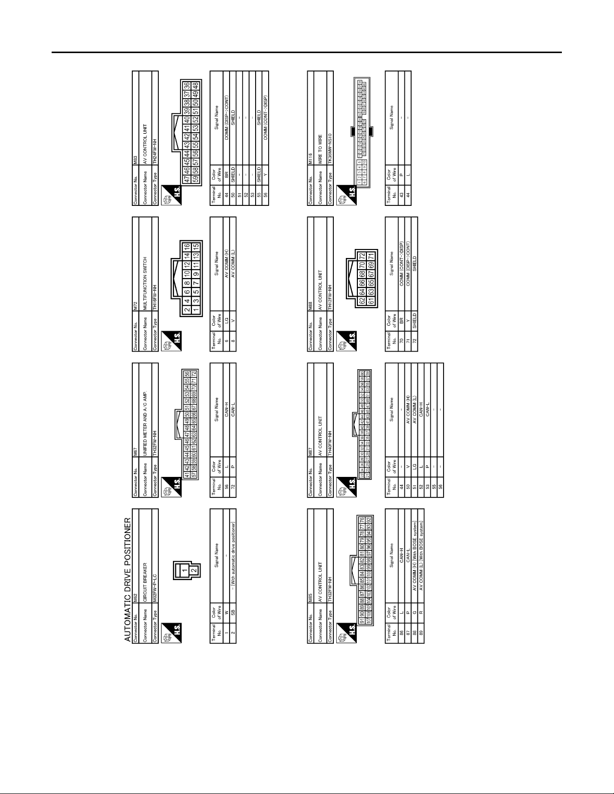
< ECU DIAGNOSIS >
B
Revision: October 2006
2007 G35 Sedan
DRIVER SEAT CONTROL UNIT
[WITH ADP]
JCJWA0028G
MIR-36
Page 37
< ECU DIAGNOSIS >
B
Revision: October 2006
2007 G35 Sedan
DRIVER SEAT CONTROL UNIT
[WITH ADP]
A
B
C
D
E
F
G
H
I
J
K
MIR
M
N
O
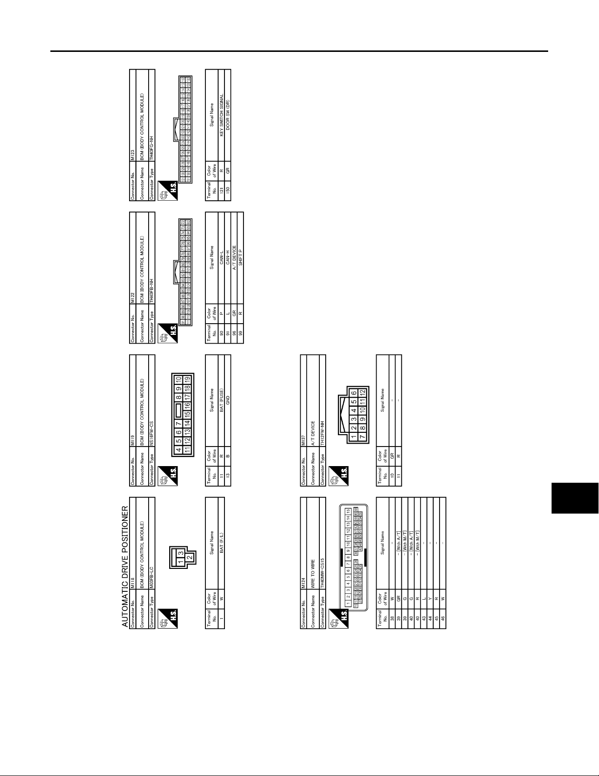
Fail Safe INFOID:0000000000962334
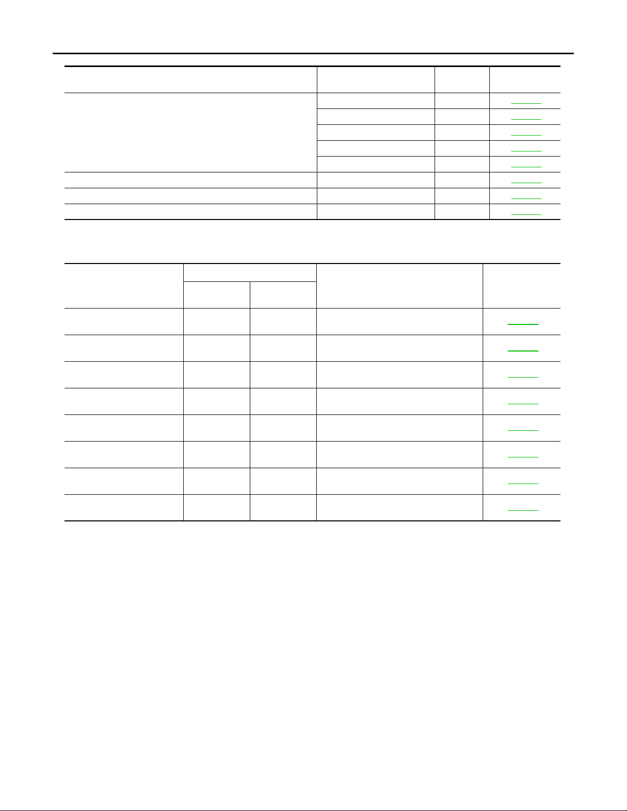
The fail-safe mode may be activated if the following symptoms are observed.
JCJWA0029G
P
MIR-37
Page 38
< ECU DIAGNOSIS >
Revision: October 2006
2007 G35 Sedan
DRIVER SEAT CONTROL UNIT
[WITH ADP]
Operating in
fail-safe mode
Only manual functions operate normally.
Only manual functions, except door mirror, operate normally. UART communication B21 28 ADP-64
Only manual functions, except seat sliding, operate normally. Seat sliding output B2112 ADP-52
Only manual functions, except seat reclining, operate normally. Seat reclining output B2113 ADP-52
Malfunction Item
CAN communication U1000 ADP-51
Tilt sensor B2118 ADP-54
Telescopic sensor B2119 ADP-57
Detent switch B2126 ADP-60
Parking brake switch B2127 ADP-62
DTC Index
*1
CONSULT-III
display
CAN COMM CIRCUIT
[U1000]
SEAT SLIDE
[B2112]
SEAT RECLINING
[B2113]
TILT SENSOR
[B2118]
TELESCO SENSOR
[B2119]
DETENT SW
[B2126]
PARKING BRAKE
[B2127]
UART COMM
[B2128]
*1
:
• 0: Current ma lfu nc tio n is pre se nt
• 1-39: Dis play ed if an y prev ious malfun ctio n is pres ent whe n current c ondit ion is normal . The nu meral v alue increa ses by one at each
IGN ON to OFF cycle from 1 to 39. The counter remains at 39 even if the number of cy cles exce eds it. Howeve r, the counter is reset
to 1 if any malfunction is detected again, the normal operation is resumed and the ignition switch is turned from OFF to ON.
Current mal-
function
Timing
Previous mal-
function
0 1-39 CAN communication ADP-51
0 1-39 Seat slide motor output ADP-52
0 1-39 Seat reclining motor output ADP-53
0 1-39 Tilt sensor input ADP-54
0 1-39 Telescopic sensor input ADP-57
0 1-39 Detention switch condition ADP-60
0 1-39 Parking brake switch condition ADP-62
0 1-39 UART communication ADP-64
Item Refere nc e page
Related
DTC
Diagnosis
INFOID:0000000000962335
MIR-38
Page 39
AUTOMATIC DRIVE POSITIONER CONTROL UNIT
Revision: October 2006
2007 G35 Sedan
< ECU DIAGNOSIS >
[WITH ADP]
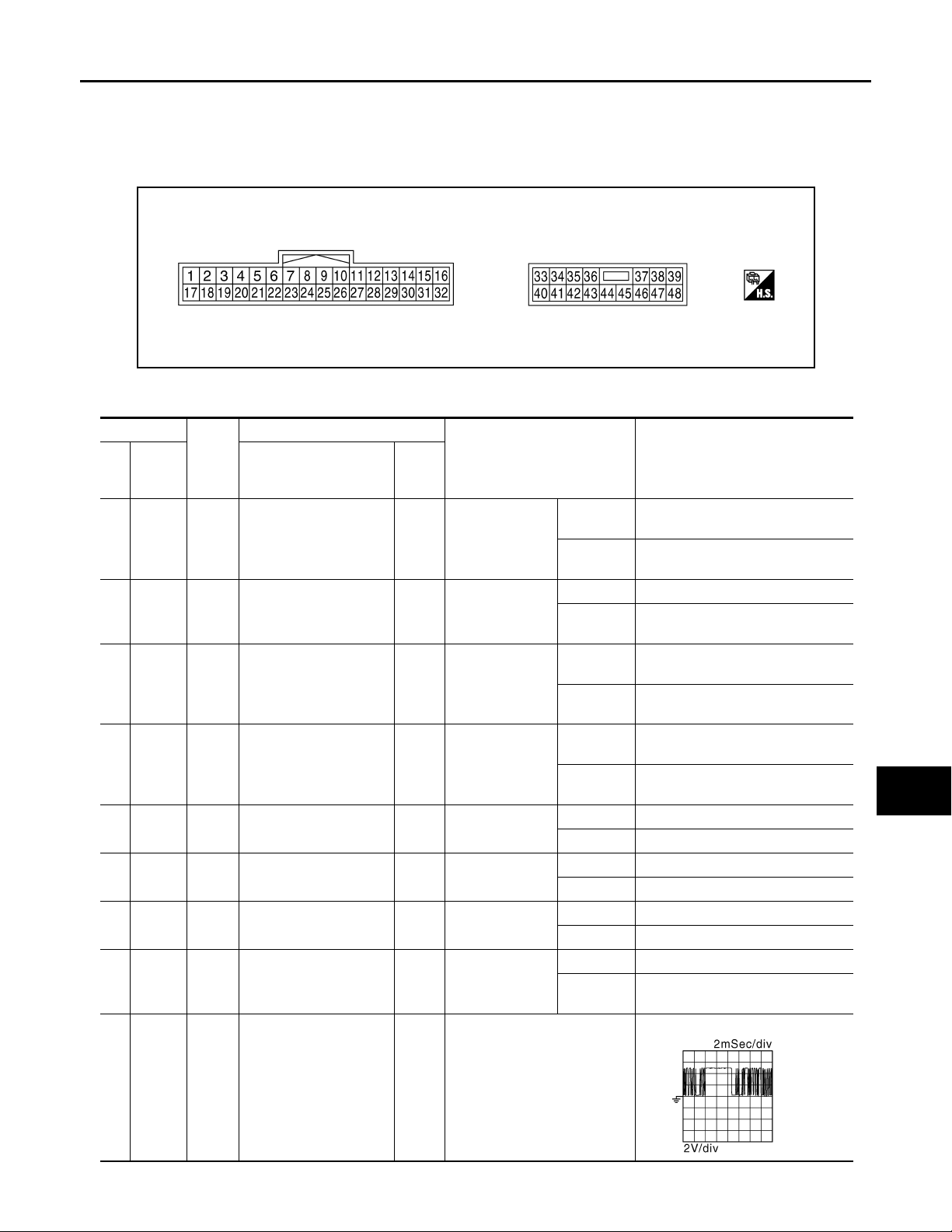
AUTOMATIC DRIVE POSITIONER CONTROL UNIT
Reference Value INFOID:0000000000962336
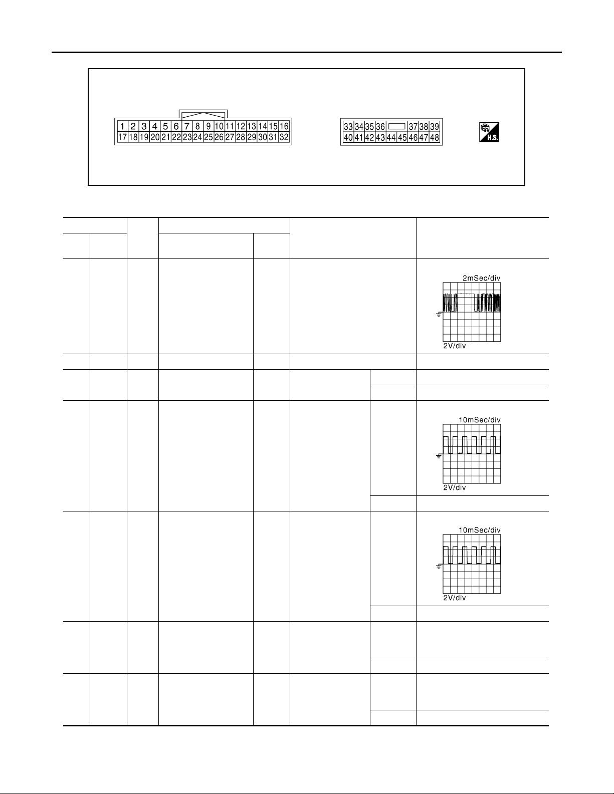
TERMINAL LAYOUT
JMJIA0199ZZ
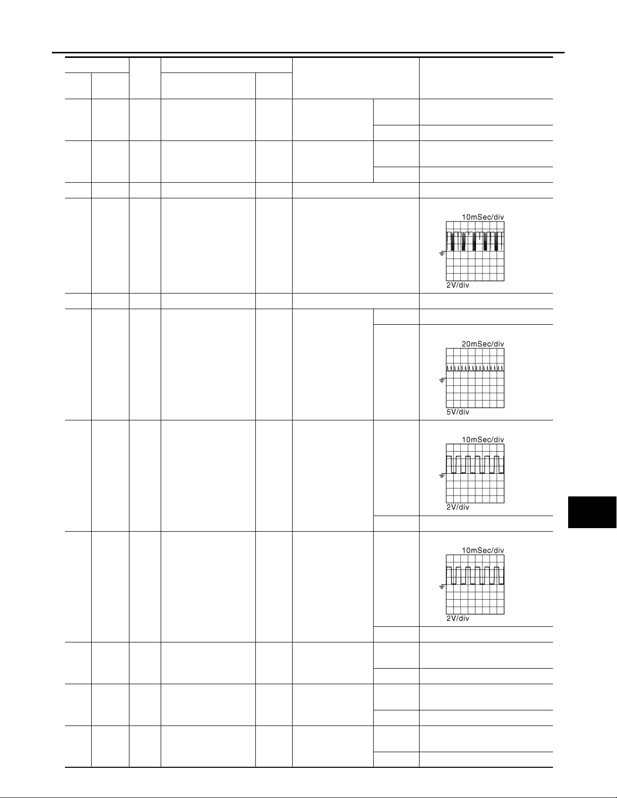
PHYSICAL VALUES
Terminal No.
Wire
+ - Signal name
1 Ground Y Tilt switch up signal Input Tilt switch
2Ground LG
3 Ground G Mirror switch up signal Input Mirror switch
4 Ground V Mirror switch left signal Input Mirror switch
5Ground R
6Ground GR
7 Ground O Tilt sensor signal Input Tilt position
9 Ground L Memory switch 1 signal Input Memory switch 1
color
Changeover switch RH
signal
Door mirror sensor (RH)
up/down signal
Door mirror sensor (LH)
up/down signal
Description
Input/
Out-
put
Input
Input
Input
Condition
Changeover
switch position
Door mirror RH
position
Door mirror LH
position
Voltage (V)
(Approx.)
Operate
(up)
Other than
above
RH 0
Neutral or
LH
Operated
(up)
Other than
above
Operated
(left)
Other than
above
Peak 3.4
Valley 0.6
Peak 3.4
Valley 0.6
Top 1.2
Bottom 3.4
Push 0
Other than
above
0
5
5
0
5
0
5
5
A
B
C
D
E
F
G
H
I
J
K
MIR
M
N
O
10 Ground V
UART communication
(TX)
Out-
Ignition switch ON
put
MIR-39
P
JMJIA0118ZZ
Page 40

AUTOMATIC DRIVE POSITIONER CONTROL UNIT
Revision: October 2006
2007 G35 Sedan
< ECU DIAGNOSIS >
[WITH ADP]
Terminal No.
Wire
+ - Signal name
11 Ground GR
12 Ground O Memory indictor 1 signal
13 Ground P Memory indictor 2 signal
14 Ground W
15 Ground
16 Ground Y
17 Ground W Tilt switch down sign al Input Tilt switch
18 Ground P
19 Ground SB
20 Ground BR Mirror switch right signal Input Mirror switch
21 Ground L
22 Ground G
23 Ground P Te lescopic sensor si gnal Input
color
GR
*2
G
Telescopic switch forward signal
Door mirror motor (RH)
up output signal
*1
Door mirror motor (RH)
left output signal
Door mirror motor (LH)
down output signal
Door mirror motor (LH)
right output signal
Changeover switch LH
signal
Mirror switch down signal
Door mirror sensor (RH)
left/right signal
Door mirror sensor (LH)
left/right signal
Description
Input/
Out-
put
Out-
put
Out-
put
Out-
put
Out-
put
Out-
put
Telescopic
switch
Memory indictor
1
Memory indictor
2
Door mirror RH
Door mirror RH
Door mirror (LH)
Changeover
switch position
Door mirror RH
position
Door mirror LH
position
Telescopic position
Input
Input
Input Mirror switch
Input
Input
Condition
Voltage (V)
(Approx.)
Operate
(forward)
Other than
above
Illuminate 0
Other than
above
Illuminate 0
Other than
above
Operate
(up)
Other than
above
Operate
(left)
Other than
above
Operate
(down)
Other than
above
Operate
(right)
Other than
above
Operate
(down)
Other than
above
LH 0
Neutral or
RH
Operate
(down)
Other than
above
Operate
(right)
Other than
above
Left edge 3.4
Right edge 0.6
Left edge 0.6
Right edge 3.4
Top 0.8
Bottom 3.4
Battery voltage
Battery voltage
Battery voltage
Battery voltage
Battery voltage
Battery voltage
0
5
0
0
0
0
0
5
5
0
5
0
5
MIR-40
Page 41
AUTOMATIC DRIVE POSITIONER CONTROL UNIT
Revision: October 2006
2007 G35 Sedan
< ECU DIAGNOSIS >
[WITH ADP]
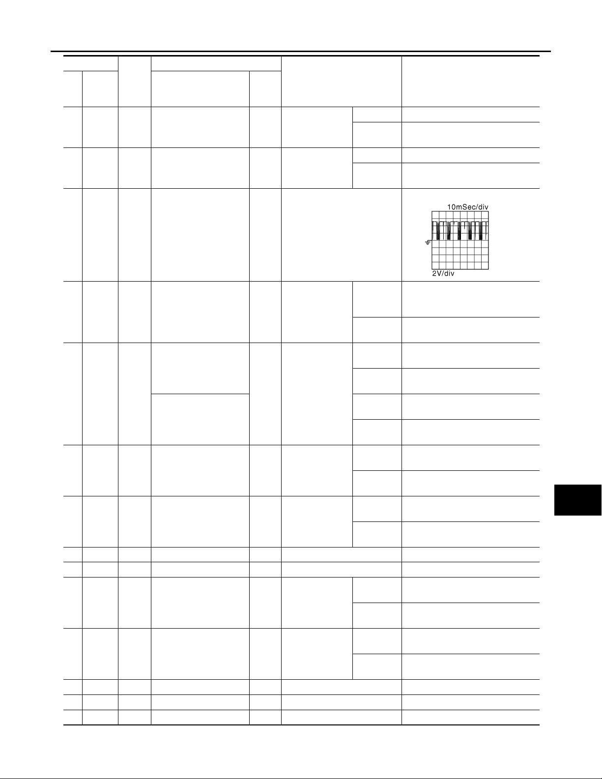
Terminal No.
Wire
+ - Signal name
24 Ground R Set switch signal Input Set switch
25 Ground SB Memory switch 2 signal Input Memory switch 2
26 Ground Y
27 Ground G
30 Ground
31 Ground LG
32 Ground L
33 Ground R Sensor power supply Input — 5
34 Ground R Power source (Fuse) Input — Battery voltage
35 Ground L
36 Ground GR
39 Ground W Power sourc e (C/ B) — Battery voltage
40 Ground B Ground — — 0
41 Ground R Sensor ground — — 0
color
*1
G
*2
R
UART communication
(RX)
Telescopic switch backward signal
Door mirror motor (RH)
down output signal
Door mirror motor (RH)
right output signal
Door mirror motor (LH)
up output signal
Door mirror motor (LH)
left output signal
Tilt motor up output signal
Telescopic motor forward output signal
Description
Input/
Out-
put
Input Ignition switch ON
Out-
put
Out-
put
Out-
put
Out-
put
Out-
put
Telescopic
switch
Door mirror (RH)
Door mirror (LH)
Door mirror (LH)
Steering tilt
Steering telescopic
Input
Condition
Voltage (V)
(Approx.)
Push 0
Other than
above
Push 0
Other than
above
Operate
(backward)
Other than
above
Operate
(down)
Other than
above
Operate
(right)
Other than
above
Operate
(up)
Other than
above
Operate
(left)
Other than
above
Operate
(up)
Other than
above
Operate
(forward)
Other than
above
Battery voltage
Battery voltage
Battery voltage
Battery voltage
Battery voltage
Battery voltage
5
5
0
5
0
0
0
0
0
0
JMJIA0121ZZ
A
B
C
D
E
F
G
H
I
J
K
MIR
M
N
O
P
MIR-41
Page 42
AUTOMATIC DRIVE POSITIONER CONTROL UNIT
Revision: October 2006
2007 G35 Sedan
< ECU DIAGNOSIS >
[WITH ADP]
Terminal No.
Wire
+ - Signal name
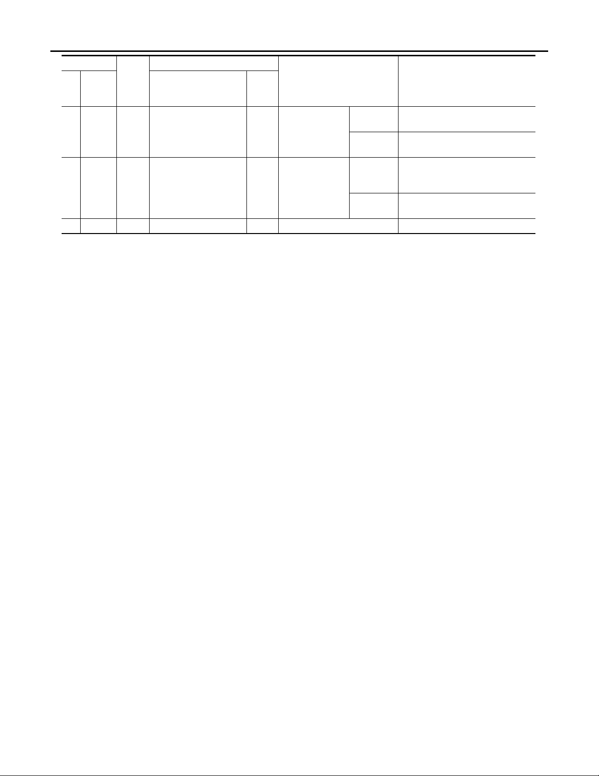
42 Ground O
44 Ground G
48 Ground B Ground — — 0
*1
: For AT models
*2
: For MT models
color
Tilt motor down output
signal
Telescopic motor backward output signal
Description
Input/
Out-
put
Out-
put
Out-
put
Condition
Steering tilt
Steering telescopic
Operate
(down)
Other than
above
Operate
(backward)
Other than
above
Voltage (V)
(Approx.)
Battery voltage
0
Battery voltage
0
MIR-42
Page 43
AUTOMATIC DRIVE POSITIONER CONTROL UNIT
B
Revision: October 2006
2007 G35 Sedan
< ECU DIAGNOSIS >
[WITH ADP]
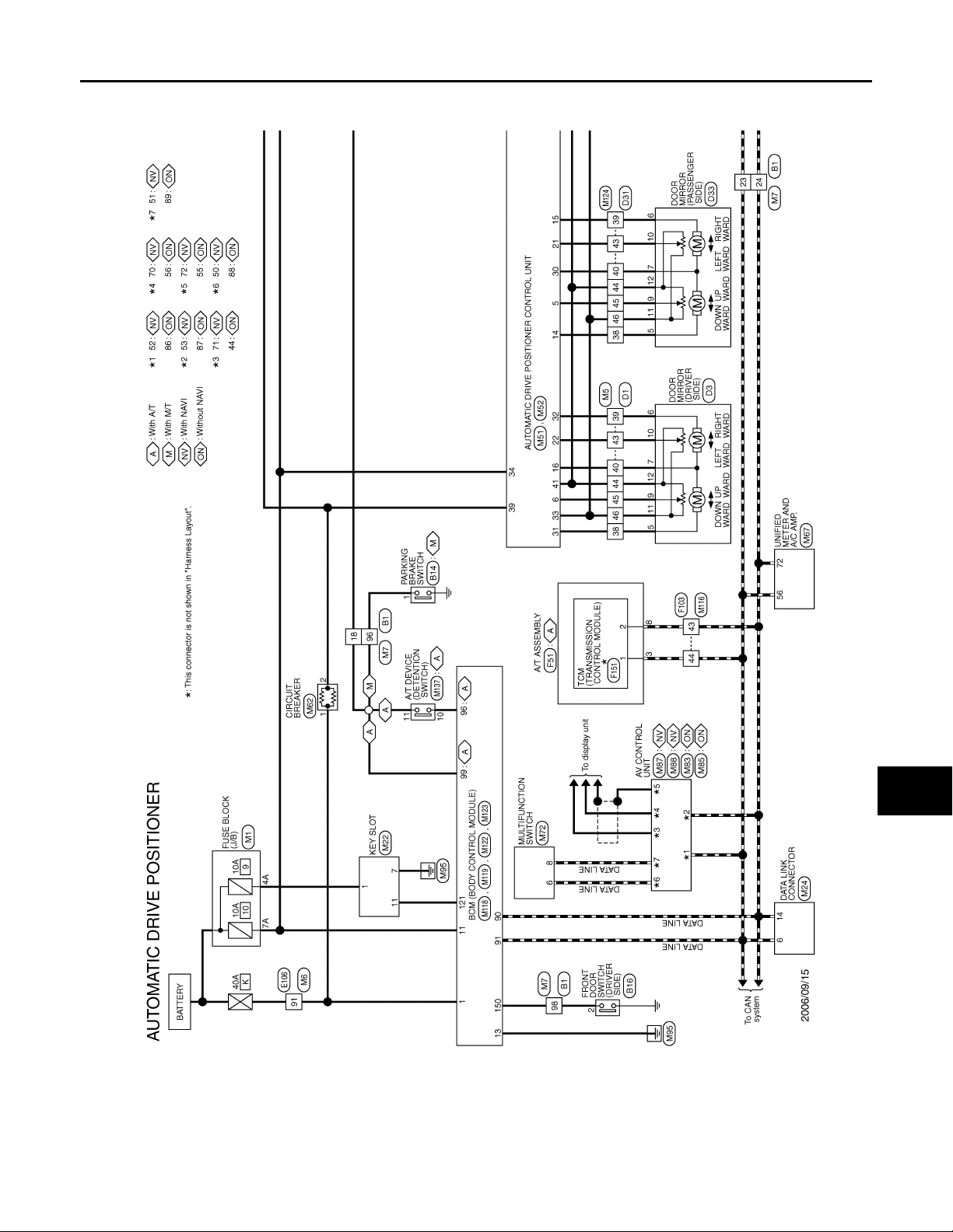
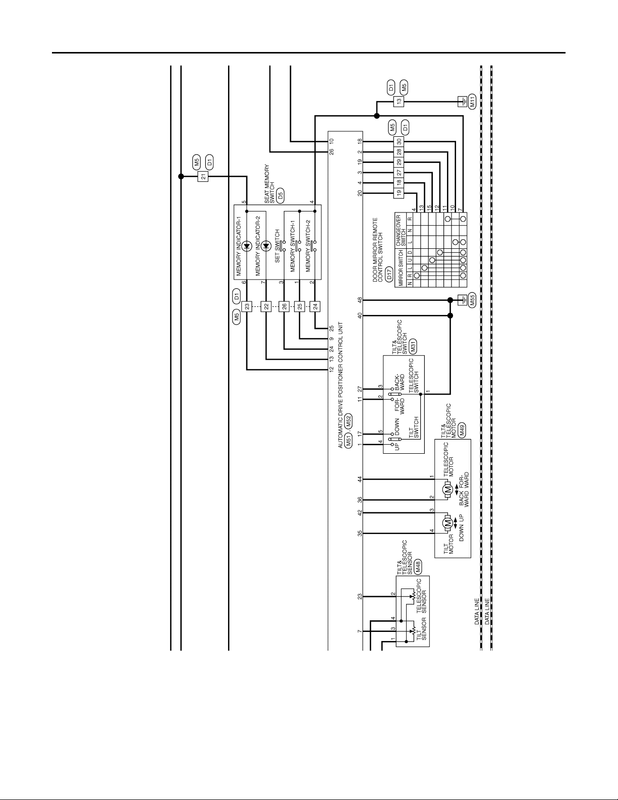
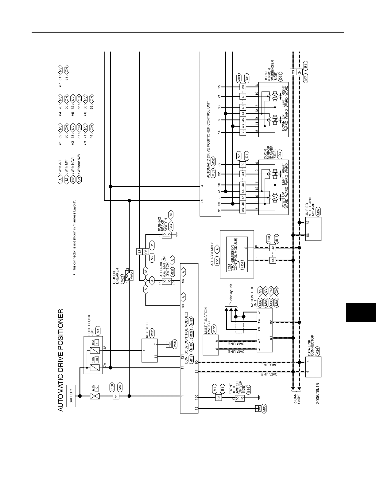
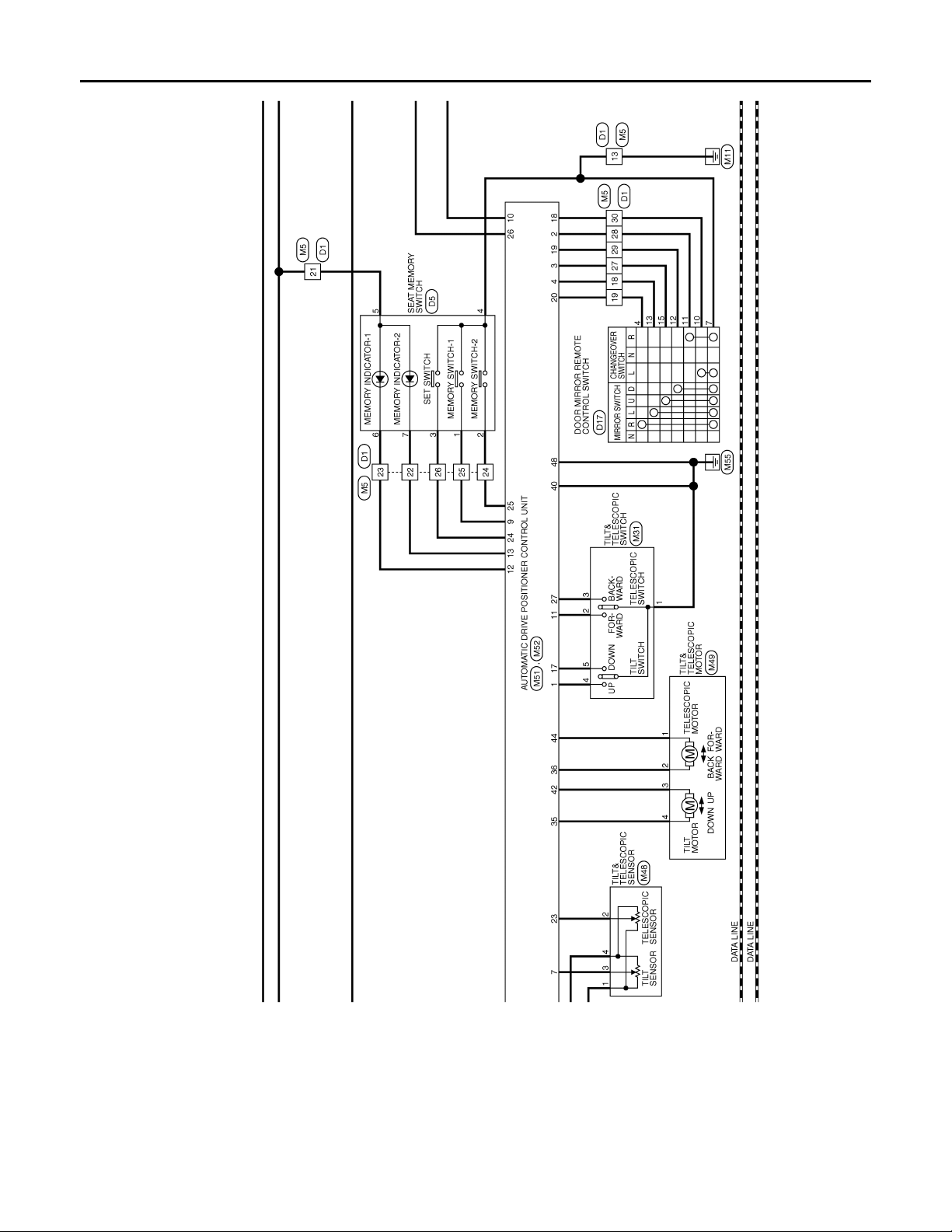
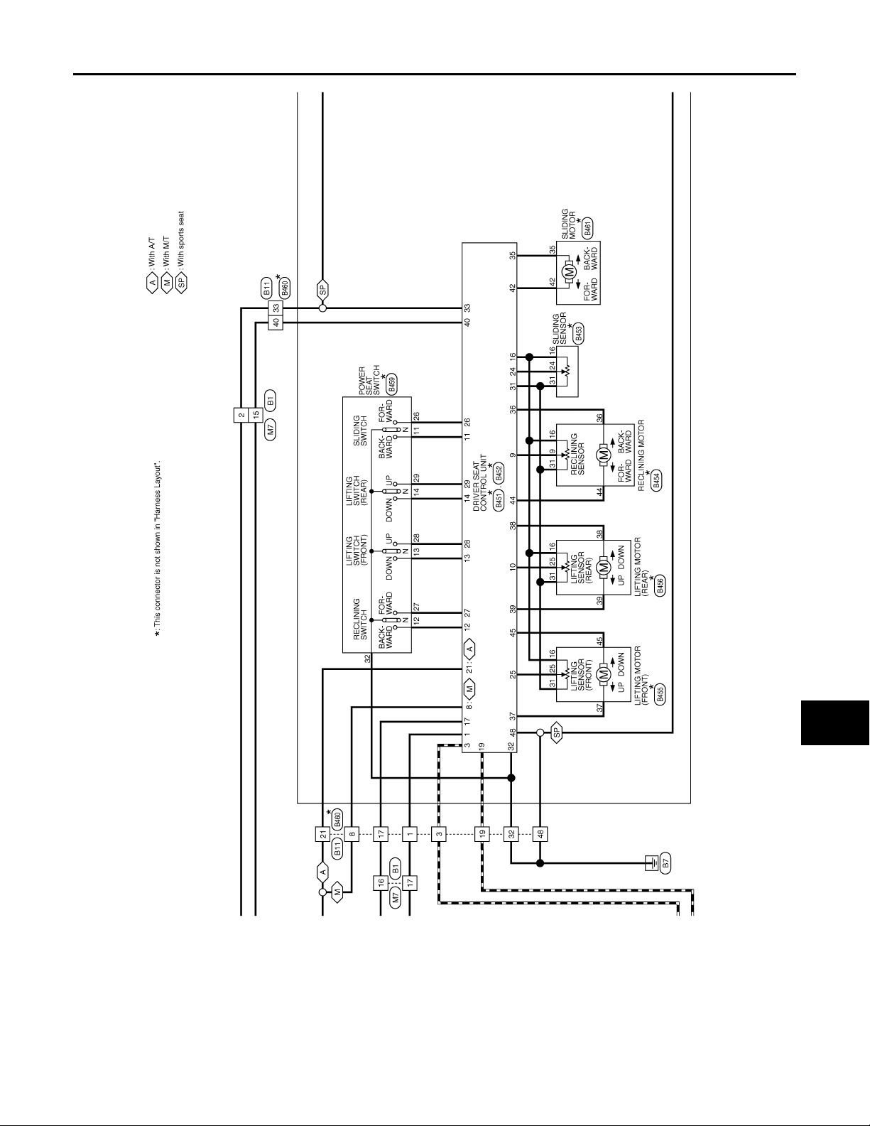
Wiring Diagram—AUTOMATIC DRIVE POSITIONER CONTROL SYSTEM—
INFOID:0000000000962337
A
B
C
D
E
F
G
H
I
J
K
MIR
M
N
O
MIR-43
JCJWA0019G
P
Page 44
AUTOMATIC DRIVE POSITIONER CONTROL UNIT
B
Revision: October 2006
2007 G35 Sedan
< ECU DIAGNOSIS >
[WITH ADP]
JCJWA0020G
MIR-44
Page 45
AUTOMATIC DRIVE POSITIONER CONTROL UNIT
B
Revision: October 2006
2007 G35 Sedan
< ECU DIAGNOSIS >
[WITH ADP]
A
B
C
D
E
F
G
H
I
J
K
MIR
M
N
O
JCJWA0021G
P
MIR-45
Page 46
AUTOMATIC DRIVE POSITIONER CONTROL UNIT
B
Revision: October 2006
2007 G35 Sedan
< ECU DIAGNOSIS >
[WITH ADP]
JCJWA0022G
MIR-46
Page 47
AUTOMATIC DRIVE POSITIONER CONTROL UNIT
B
Revision: October 2006
2007 G35 Sedan
< ECU DIAGNOSIS >
[WITH ADP]
A
B
C
D
E
F
G
H
I
J
K
MIR
M
N
O
JCJWA0023G
P
MIR-47
Page 48
AUTOMATIC DRIVE POSITIONER CONTROL UNIT
B
Revision: October 2006
2007 G35 Sedan
< ECU DIAGNOSIS >
[WITH ADP]
JCJWA0024G
MIR-48
Page 49
AUTOMATIC DRIVE POSITIONER CONTROL UNIT
B
Revision: October 2006
2007 G35 Sedan
< ECU DIAGNOSIS >
[WITH ADP]
A
B
C
D
E
F
G
H
I
J
K
MIR
M
N
O
JCJWA0025G
P
MIR-49
Page 50
AUTOMATIC DRIVE POSITIONER CONTROL UNIT
B
Revision: October 2006
2007 G35 Sedan
< ECU DIAGNOSIS >
[WITH ADP]
JCJWA0026G
MIR-50
Page 51
AUTOMATIC DRIVE POSITIONER CONTROL UNIT
B
Revision: October 2006
2007 G35 Sedan
< ECU DIAGNOSIS >
[WITH ADP]
A
B
C
D
E
F
G
H
I
J
K
MIR
M
N
O
JCJWA0027G
P
MIR-51
Page 52
AUTOMATIC DRIVE POSITIONER CONTROL UNIT
B
Revision: October 2006
2007 G35 Sedan
< ECU DIAGNOSIS >
[WITH ADP]
JCJWA0028G
MIR-52
Page 53
AUTOMATIC DRIVE POSITIONER CONTROL UNIT
B
Revision: October 2006
2007 G35 Sedan
< ECU DIAGNOSIS >
[WITH ADP]
A
B
C
D
E
F
G
H
I
J
K
MIR
M
N
O
JCJWA0029G
P
MIR-53
Page 54

NONE OF THE DOOR MIRROR CAN BE OPERATED USING ANY SWITCH
Revision: October 2006
2007 G35 Sedan
< SYMPTOM DIAGNOSIS >
[WITH ADP]
SYMPTOM DIAGNOSIS
NONE OF THE DOOR MIRROR CAN BE OPERA TED USING ANY SWITCH
Diagnosis Procedure INFOID:0000000000962338
1.CHECK AUTOMATIC DRIVE POSITIONER SYSTEM
Check automatic drive positioner system operation.
Refer to ADP-5, "
Is the inspection result normal?
YES >> GO TO 2.
NO >> Repair or replace the malfunctioning parts.
2.CHECK MIRROR SWITCH
Check mirror switch.
Refer to MIR-11, "
Is the inspection result normal?
YES >> GO TO 3.
NO >> Repair or replace the malfunctioning parts.
3.CHECK CHANGEOVER SWITCH
Work Fl ow".
Component Function Check".
Check changeover switch.
Refer to MIR-14, "
Is the inspection result normal?
YES >> Refer to GI-39, "Intermittent Incident".
NO >> Repair or replace the malfunctioning parts.
Component Function Check".
MIR-54
Page 55

< SYMPTOM DIAGNOSIS >
Revision: October 2006
2007 G35 Sedan
DOOR MIRROR DOES NOT OPERATE
[WITH ADP]
DOOR MIRROR DOES NOT OPERATE
Diagnosis Procedure INFOID:0000000000962339
1.CHECK MIRROR SWITCH
Check mirror switch.
Refer to MIR-11, "
Is the inspection result normal?
YES >> GO TO 2.
NO >> Repair or replace the malfunctioning parts.
Component Function Check".
2.CHECK CHANGEOVER SWITCH
Check changeover switch.
Refer to MIR-14, "
Is the inspection result normal?
YES >> GO TO 3.
NO >> Repair or replace the malfunctioning parts.
Component Function Check".
3.CHECK DOOR MIRROR MOTOR
Check door mirror motor operation.
Refer to MIR-16, "
Is the inspection result normal?
YES >> Refer to GI-39, "Intermittent Incident".
NO >> Repair or replace the malfunctioning parts.
Component Function Check".
A
B
C
D
E
F
G
H
I
J
K
MIR
M
N
O
P
MIR-55
Page 56

AUTO ANTI-DAZZLING INSIDE MIRROR DOES NOT OPERATE
Revision: October 2006
2007 G35 Sedan
< SYMPTOM DIAGNOSIS >
[WITH ADP]
AUTO ANTI-DAZZLING INSIDE MIRROR DOES NOT OPERATE
Diagnosis Procedure INFOID:0000000000962340
1.CHECK AUTO ANTI-DAZZLING INSIDE MIRROR
Check auto anti-dazzling inside mirror.
Refer to MIR-19, "
Is the inspection result normal?
YES >> Refer to GI-39, "Intermittent Incident".
NO >> Repair or replace the malfunctioning parts.
Component Function Check".
MIR-56
Page 57
SQUEAK AND RATTLE TROUBLE DIAGNOSES
Revision: October 2006
2007 G35 Sedan
< SYMPTOM DIAGNOSIS >
[WITH ADP]
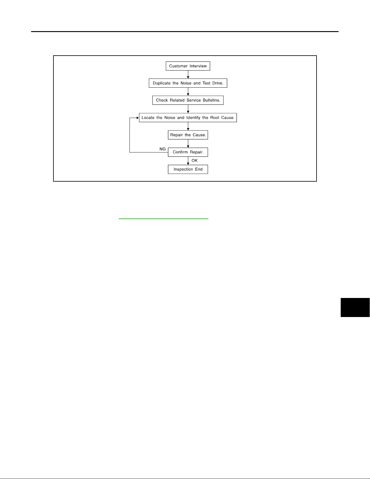
SQUEAK AND RATTLE TROUBLE DIAGNOSES
Work Flow INFOID:0000000000962341
SBT842
CUSTOMER INTERVIEW
Interview the customer if possible, to determine the conditions that exist when the noise occurs. Use the Diagnostic Worksheet during the interview to document the facts and conditions when the noise occurs and any of
customer's comments; refer to MIR-91, "
conditions that exist when the noise occurs.
• The customer may not be able to provide a detailed description or the location of the noise. Attempt to obtain
all the facts and conditions that exist when the noise occurs (or does not occur).
• If there is more than one noise in the vehicle, perform a diagnosis and repair the noise that the customer is
concerned about. This can be accomplished by performing a cruise test on the vehicle with the customer.
• After identifying the type of noise, isolate the noise in terms of its characteristics. The noise characteristics
are provided so the customer, service adviser and technician are all speaking the same language when
defining the noise.
• Squeak —(Like tennis shoes on a clean floor)
Squeak characteristics include the light contact/fast movement/brought on by road conditions/hard surfaces=higher pitch noise/softer surfaces=lower pitch noises/edge to surface=chirping
• Creak—(Like walking on an old wooden floor)
Creak characteristics include firm contact/slow movement/twisting with a rotational movement/pitch dependent on materials/often brought on by activity.
• Rattle—(Like shaking a baby rattle)
Rattle characteristics include the fast repeated contact/vibration or similar movement/loose parts/missing
clip or fastener/incorrect clearance.
• Knock —(Like a knock on a door)
Knock characteristics include hollow sounding/sometimes repeating/often brought on by driver action.
• Tick—(Like a clock second hand)
Tick characteristics include gentle contacting of light materials/loose components/can be caused by driver
action or road conditions.
• Thump—(Heavy, muffled knock noise)
Thump characteristics include softer knock/dead sound often brought on by activity.
• Buzz—(Like a bumblebee)
Buzz characteristics include high frequency rattle/firm contact.
• Often the degree of acceptable noise level will vary depending up on the person. A noise that you may judge
as acceptable may be very irritating to the customer.
• Weather conditions, especially humidity and temperature, may have a great effect on noise level.
Diagnostic Worksheet". This information is necessary to duplicate the
A
B
C
D
E
F
G
H
I
J
K
MIR
M
N
O
P
DUPLICATE THE NOISE AND TEST DRIVE
If possible, drive the vehicle with the customer until the noise is duplicated. Note any additional information on
the Diagnostic Worksheet regarding the conditions or location of the noise. This information can be used to
duplicate the same conditions when you confirm the repair.
MIR-57
Page 58

SQUEAK AND RATTLE TROUBLE DIAGNOSES
Revision: October 2006
2007 G35 Sedan
< SYMPTOM DIAGNOSIS >
If the noise can be duplicated easily during the test drive, to help identify the source of the noise, try to duplicate the noise with the vehicle stopped by doing one or all of the following:
1) Close a door.
2) Tap or push/pull around the area where the noise appears to be coming from.
3) Rev the engine.
4) Use a floor jack to recreate vehicle “twist”.
5) At idle, apply engine load (electrical load, half-clutch on M/T models, drive position on A/T models).
6) Raise the vehicle on a hoist and hit a tire with a rubber hammer.
• Drive the vehicle and attempt to duplicate the conditions the customer states exist when the noise occurs.
• If it is difficult to duplicate the noise, drive the vehicle slowly on an undulating or rough road to stress the
vehicle body.
CHECK RELATED SERVICE BULLETINS
After verifying the customer concern or symptom, check ASIST for Technical Service Bulletins (TSBs) related
to that concern or symptom.
If a TSB relates to the symptom, follow the procedure to repair the noise.
LOCATE THE NOISE AND IDENTIFY THE ROOT CAUSE
1. Narrow down the noise to a general area. To help pinpoint the source of the noise, use a listening tool
(Chassis Ear: J-39570, Engine Ear and mechanics stethoscope).
2. Narrow down the noise to a more specific area and identify the cause of the noise by:
• removing the components in the area that you suspect the noise is coming from.
Do not use too much force when removing clips and fasteners, otherwise clips and fastener can be broken
or lost during the repair, resulting in the creation of new noise.
• tapping or pushing/pulling the component that you suspect is causing the noise.
Do not tap or push/pull the component with excessive force, otherwise the noise will be eliminated only temporarily.
• feeling for a vibration with your hand by touching the component(s) that you suspect is (are) causing the
noise.
• placing a piece of paper between components that you suspect are causing the noise.
• looking for loose components and contact marks.
Refer to MIR-89, "
Inspection Procedure".
[WITH ADP]
REPAIR THE CAUSE
• If the cause is a loose component, tighten the component securely.
• If the cause is insufficient clearance between components:
- separate components by repositioning or loosening and retightening the component, if possible.
- insulate components with a suitable insulator such as urethane pads, foam blocks, felt cloth tape or urethane
tape. A Nissan Squeak and Rattle Kit (J-43980) is available through your authorized Nissan Parts Department.
CAUTION:
Do not use excessive force as many components are constructed of plastic and may be damaged.
NOTE:
Always check with the Parts Department for the latest parts information.
The following materials are contained in the Nissan Squeak and Rattle Kit (J-43980). Each item can be
ordered separately as needed.
URETHANE PADS [1.5 mm (0.059 in) thick]
Insulates connectors, harness, etc.
76268-9E005: 100 × 135 mm (3.94 × 5.31 in)/76884-71L01: 60 × 85 mm (2.36 × 3.35 in)/7688471L02:15 × 25 mm (0.59 × 0.98 in)
INSULATOR (Foam blocks)
Insulates components from contact. Can be used to fill space behind a panel.
73982-9E000: 45 mm (1.77 in) thick, 50 × 50 mm (1.97 × 1.97 in)/7398250Y00: 10 mm (0.39 in) thick, 50 × 50 mm (1.97 × 1.97 in)
INSULATOR (Light foam block)
80845-71L00: 30 mm (1.18 in) thick, 30 × 50 mm (1.18 × 1.97in)
FELT CLOTHTAPE
Used to insulate where movement does not occur. Ideal for instrument panel applications.
68370-4B000: 15 × 25 mm (0.59 × 0.98 in) pad/68239-13E00: 5 mm (0.20 in) wide tape roll
The following materials, not found in the kit, can also be used to repair squeaks and rattles.
UHMW (TEFLON) TAPE
MIR-58
Page 59

SQUEAK AND RATTLE TROUBLE DIAGNOSES
Revision: October 2006
2007 G35 Sedan
< SYMPTOM DIAGNOSIS >
Insulates where slight movement is present. Ideal for instrument panel applications.
SILICONE GREASE
Used in place of UHMW tape that will be visible or not fit. Will only last a few months.
SILICONE SPRAY
Use when grease cannot be applied.
DUCT TAPE
Use to eliminate movement.
[WITH ADP]
A
B
CONFIRM THE REPAIR
Confirm that the cause of a noise is repaired by test driving the vehicle.Operate the vehicle under the same
conditions as when the noise originally occurred. Refer to the notes on the Diagnostic Worksheet.
Inspection Procedure INFOID:0000000000962342
Refer to Table of Contents for specific component removal and installationinformation.
INSTRUMENT PANEL
Most incidents are caused by contact and movement between:
1. The cluster lid A and instrument panel
2. Acrylic lens and combination meter housing
3. Instrument panel to front pillar garnish
4. Instrument panel to windshield
5. Instrument panel mounting pins
6. Wiring harnesses behind the combination meter
7. A/C defroster duct and duct joint
These incidents can usually be located by tapping or moving the components to duplicate the noise or by
pressing on the components while driving to stop the noise. Most of these incidents can be repaired by
applying felt cloth tape or silicon spray (in hard to reach areas). Urethane pads can be used to insulate
wiring harness.
CAUTION:
Do not use silicone spray to isolate a squeak or rattle. If you saturatethe area with silicone, you
will not be able to recheck the repair.
CENTER CONSOLE
Components to pay attention to include:
1. Shifter assembly cover to finisher
2. A/C control unit and cluster lid C
3. Wiring harnesses behind audio and A/C control unit
The instrument panel repair and isolation procedures also apply to thecenter console.
C
D
E
F
G
H
I
J
K
MIR
DOORS
Pay attention to the:
1. Finisher and inner panel making a slapping noise
2. Inside handle escutcheon to door finisher
3. Wiring harnesses tapping
4. Door striker out of alignment causing a popping noise on startsand stops
Tapping or moving the components or pressing on them while driving to duplicate the conditions can isolate
many of these incidents. You can usually insulate the areas with felt cloth tape or insulator foam blocks from
the Nissan Squeak and Rattle Kit (J-43980) to repair the noise.
TRUNK
Trunk noises are often caused by a loose jack or loose items put intothe trunk by the owner.
In addition look for:
1. Trunk lid dumpers out of adjustment
2. Trunk lid striker out of adjustment
3. The trunk lid torsion bars knocking together
4. A loose license plate or bracket
M
N
O
P
MIR-59
Page 60

SQUEAK AND RATTLE TROUBLE DIAGNOSES
Revision: October 2006
2007 G35 Sedan
< SYMPTOM DIAGNOSIS >
Most of these incidents can be repaired by adjusting, securing or insulatingthe item(s) or component(s) causing the noise.
SUNROOF/HEADLINING
Noises in the sunroof/headlining area can often be traced to one of the following:
1. Sunroof lid, rail, linkage or seals making a rattle or light knockingnoise
2. Sunvisor shaft shaking in the holder
3. Front or rear windshield touching headlining and squeaking
Again, pressing on the components to stop the noise while duplicatingthe conditions can isolate most of these
incidents. Repairs usually consistof insulating with felt cloth tape.
SEATS
When isolating seat noise it's important to note the position the seatis in and the load placed on the seat when
the noise is present. These conditionsshould be duplicated when verifying and isolating the cause of the
noise.
Cause of seat noise include:
1. Headrest rods and holder
2. A squeak between the seat pad cushion and frame
3. The rear seatback lock and bracket
These noises can be isolated by moving or pressing on the suspectedcomponents while duplicating the condi-
tions under which the noise occurs.Most of these incidents can be repaired by repositioning the component
orapplying urethane tape to the contact area.
[WITH ADP]
UNDERHOOD
Some interior noise may be caused by components under the hood or onthe engine wall. The noise is then
transmitted into the passenger compartment.
Causes of transmitted underhood noise include:
1. Any component mounted to the engine wall
2. Components that pass through the engine wall
3. Engine wall mounts and connectors
4. Loose radiator mounting pins
5. Hood bumpers out of adjustment
6. Hood striker out of adjustment
These noises can be difficult to isolate since they cannot be reached from the interior of the vehicle. The best
method is to secure, move or insulate one component at a time and test drive the vehicle. Also, engine RPM
or load can be changed to isolate the noise. Repairs can usually be made by moving, adjusting, securing, or
insulating the component causing the noise.
MIR-60
Page 61
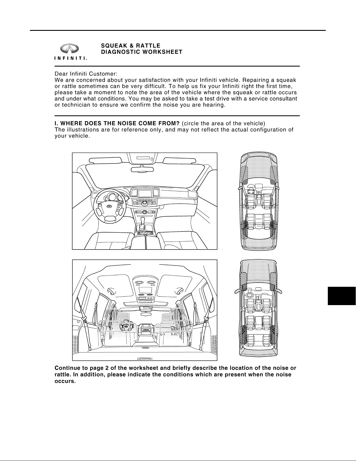
SQUEAK AND RATTLE TROUBLE DIAGNOSES
Revision: October 2006
2007 G35 Sedan
< SYMPTOM DIAGNOSIS >
[WITH ADP]
Diagnostic Worksheet INFOID:0000000000962343
A
B
C
D
E
F
G
H
I
J
K
MIR
M
N
O
PIIB8741E
P
MIR-61
Page 62

SQUEAK AND RATTLE TROUBLE DIAGNOSES
Revision: October 2006
2007 G35 Sedan
< SYMPTOM DIAGNOSIS >
[WITH ADP]
PIIB8742E
MIR-62
Page 63

< PRECAUTION >
Revision: October 2006
2007 G35 Sedan
PRECAUTIONS
[WITH ADP]
PRECAUTION
PRECAUTIONS
Precaution for Supplemental Restraint System (SRS) "AIR BAG" and "SEAT BELT PRE-TENSIONER" INFOID:0000000000962344
The Supplemental Restraint System such as “AIR BAG” and “SEAT BELT PRE-TENSIONER”, used along
with a front seat belt, helps to reduce the risk or severity of injury to the driver and front passenger for certain
types of collision. This system includes seat belt switch inputs and dual stage front air bag modules. The SRS
system uses the seat belt switches to determine the front air bag deployment, and may only deploy one front
air bag, depending on the severity of a collision and whether the front occupants are belted or unbelted.
Information necessary to service the system safely is included in the SRS and SB section of this Service Manual.
WARNING:
• To avoid rendering the SRS inoperative, which could increase the risk of personal injury or death in
the event of a collision which would result in air bag inflation, all maintenance must be performed by
an authorized NISSAN/INFINITI dealer.
• Improper maintenance, including incorrect removal and installation of the SRS, can lead to personal
injury caused by unintentional activation of the system. For removal of Spiral Cable and Air Bag
Module, see the SRS section.
• Do not use electrical test equipment on any circuit related to the SRS unless instructed to in this
Service Manual. SRS wiring harnesses can be identified by yellow and/or orange harnesses or harness connectors.
A
B
C
D
E
F
G
H
I
J
K
MIR
M
N
O
P
MIR-63
Page 64
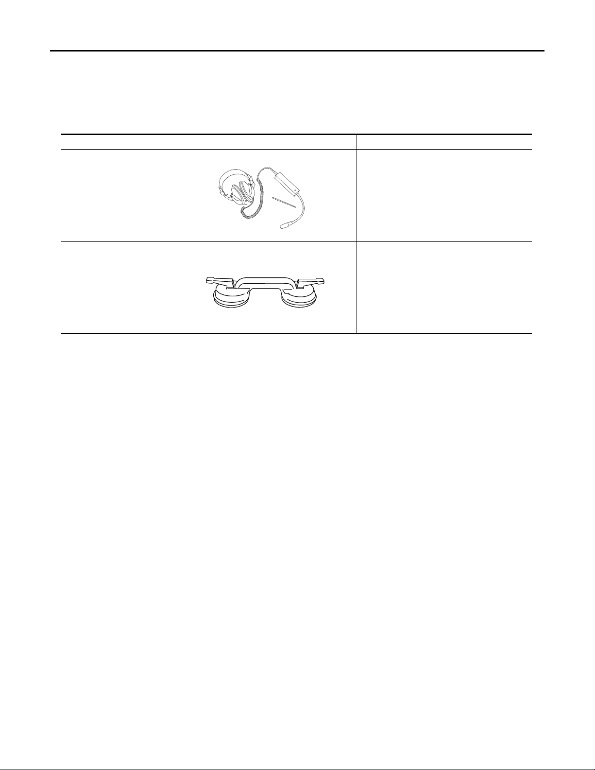
PREPARATION
Revision: October 2006
2007 G35 Sedan
< PREPARATION >
[WITH ADP]
PREPARATION
PREPARATION
Commercial Service Tools INFOID:0000000000962345
Tool name Description
Engine ear Locating the noise
SIIA0995E
Suction lifter Holding the door glass
PIIB1805J
MIR-64
Page 65

PRE-INSPECTION FOR DIAGNOSTIC
Revision: October 2006
2007 G35 Sedan
< ON-VEHICLE MAINTENANCE >
[WITH ADP]
ON-VEHICLE MAINTENANCE
PRE-INSPECTION FOR DIAGNOSTIC
Basic Inspection INFOID:0000000000962346
BASIC INSPECTION
1.INSPECTION START
1. Check the service history.
2. Check the following parts.
• Fuse/circuit breaker blown.
• Poor connection, open or short circuit of harness connector.
• Battery voltage.
Is the inspection result normal?
YES >> Inspection end.
NO >> Repair or replace the malfunctioning parts.
A
B
C
D
E
F
G
H
I
J
K
MIR
M
N
O
P
MIR-65
Page 66
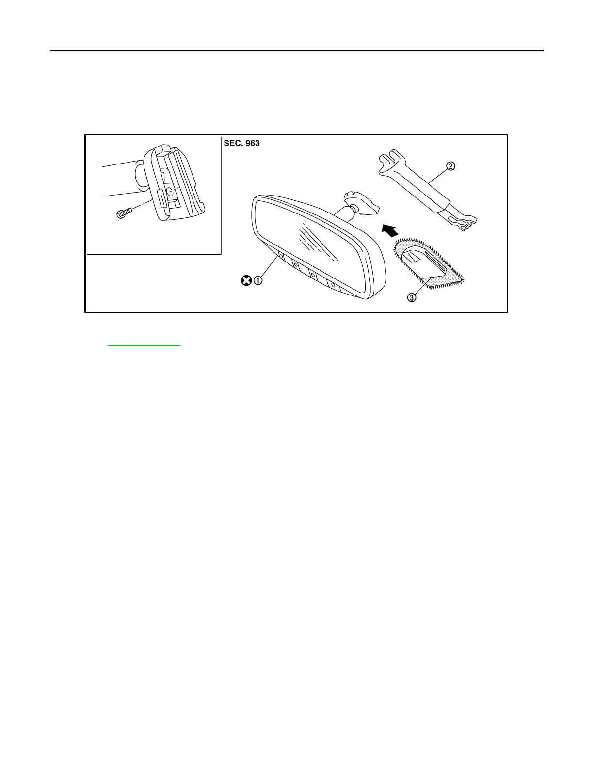
INSIDE MIRROR
Revision: October 2006
2007 G35 Sedan
< ON-VEHICLE REPAIR >
[WITH ADP]
ON-VEHICLE REPAIR
INSIDE MIRROR
Exploded View INFOID:0000000000962347
JMLIA0015ZZ
1. Inside mirror 2. Inside mirror finisher (if equipped) 3. Mirror base
Refer to GI-4, "
Components" for symbols in the figure.
Removal and Installation INFOID:0000000000962348
REMOVAL
1. Remove inside mirror finisher (if equipped).
2. Remove nut of mirror base.
3. Slide the mirror upward to remove.
4. Disconnect the connector (if equipped).
INSTALLATION
Install in the reverse order of removal.
MIR-66
Page 67
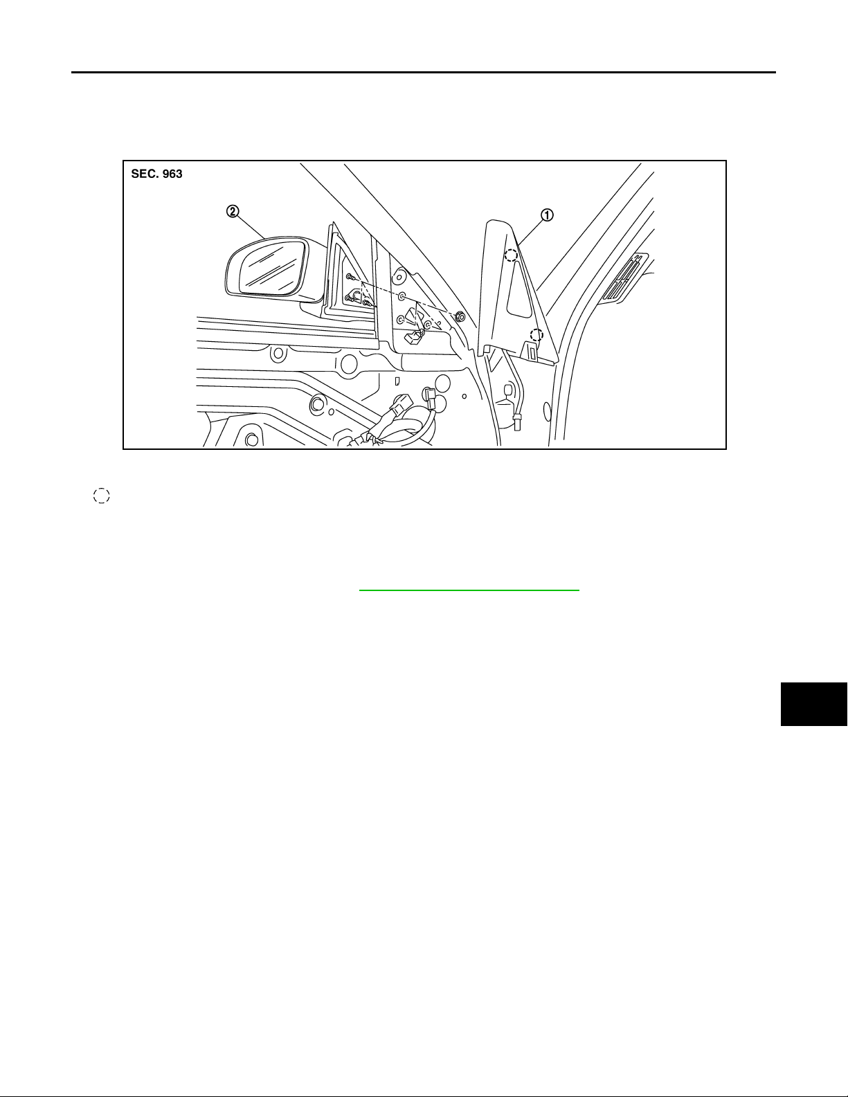
< ON-VEHICLE REPAIR >
Revision: October 2006
2007 G35 Sedan
DOOR MIRROR
[WITH ADP]
DOOR MIRROR
Exploded View INFOID:0000000000962349
JMLIA0001ZZ
1. Corner cover 2. Door mirror assembly
Clip
A
B
C
D
E
F
G
H
Removal and Installation INFOID:0000000000962350
REMOVAL
1. Remove the front door finisher. Refer to INT-10, "Removal and Installation".
2. Remove the corner cover.
3. Disconnect the door mirror harness connector.
4. Remove the door mirror mounting nuts, and remove the door mirror assembly.
CAUTION:
Do not damage the mirror bodies.
INSTALLATION
Install in the reverse order of removal.
CAUTION:
Do not damage the mirror bodies.
I
J
K
MIR
M
N
O
P
MIR-67
Page 68
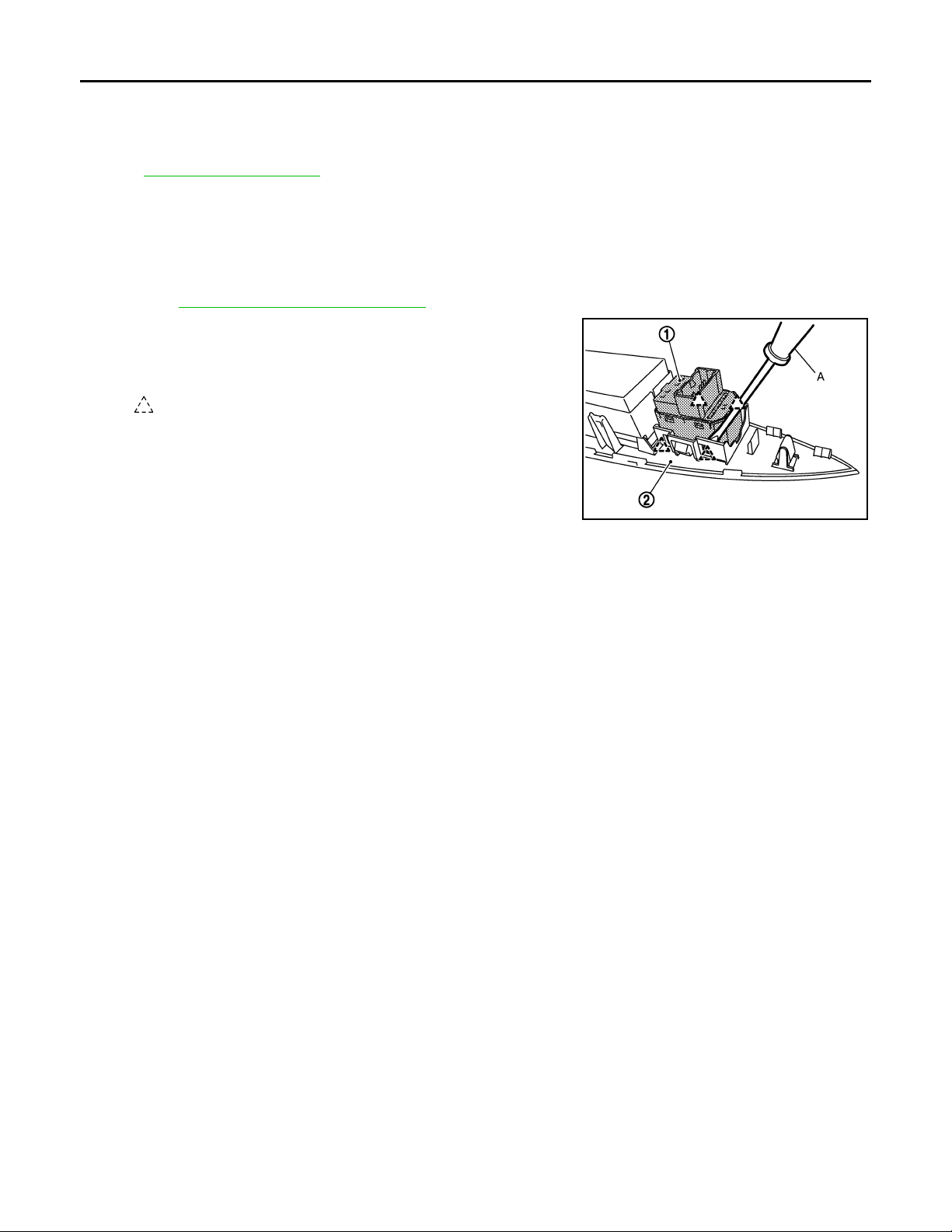
DOOR MIRROR REMOTE CONTROL SWITCH
Revision: October 2006
2007 G35 Sedan
< ON-VEHICLE REPAIR >
[WITH ADP]
DOOR MIRROR REMOTE CONTROL SWITCH
Exploded View INFOID:0000000000962351
Refer to INT-10, "Exploded View".
Removal and Installation INFOID:0000000000962352
REMOVAL
1. Remove the power window main switch finisher (2).
Refer to INT-10, "
2. Remove door mirror remote control switch (1) from power window main switch finisher (2) using screw driver (A).
Removal and Installation".
: Pawl
INSTALLATION
Install in the reverse order of removal.
JMLIA0011ZZ
MIR-68
Page 69
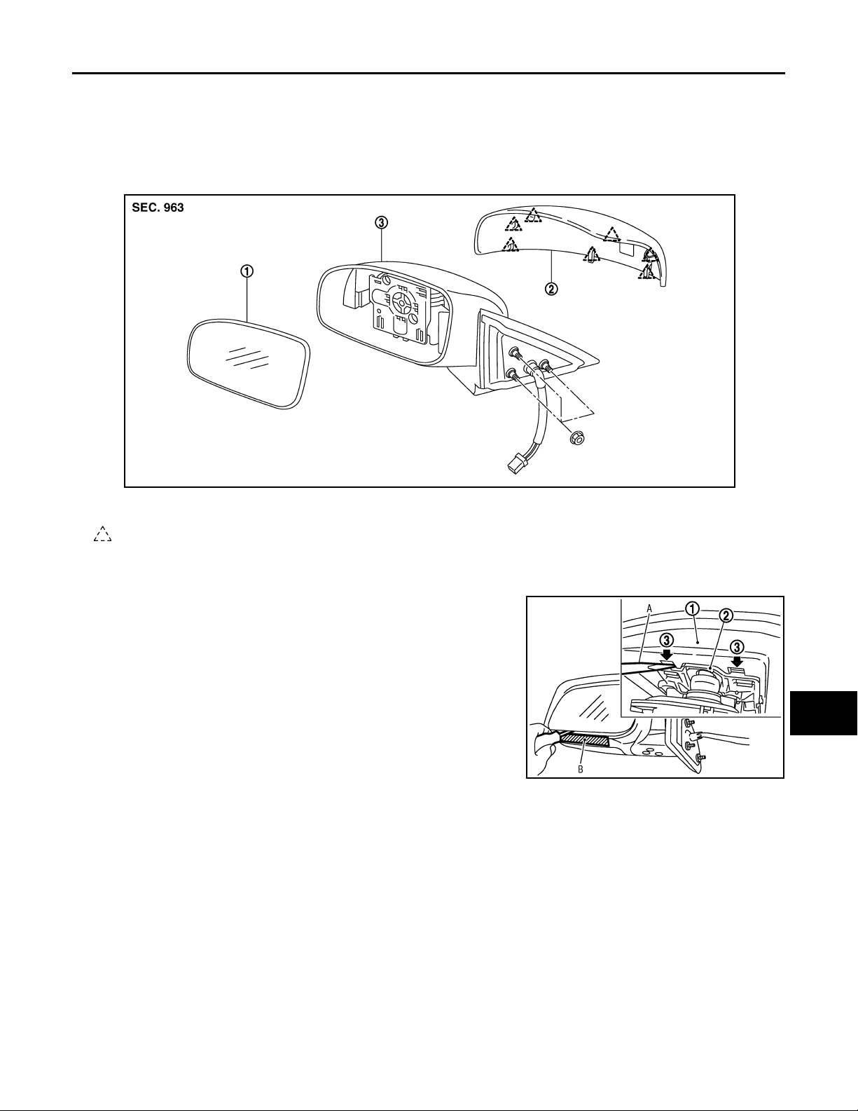
< DISASSEMBLY AND ASSEMBLY >
Revision: October 2006
2007 G35 Sedan
DOOR MIRROR
[WITH ADP]
DISASSEMBLY AND ASSEMBLY
DOOR MIRROR
Exploded View INFOID:0000000000962353
JMLIA0002ZZ
1. Mirror (mirror holder) 2. Mirror assembly 3. Mirror cover
Pawl
Disassembly INFOID:0000000000962354
A
B
C
D
E
F
G
H
I
1. Place the mirror body with mirror glass facing upward.
2. Put a strip of protective tape B on mirror body.
3. As shown in the figure, insert a small slotted screwdriver A into
the recess between mirror base (mirror holder)(1) and mirror
holder bracket (2). Push up two pawls (3) to remove mirror
holder lower half side.
NOTE:
When pushing up pawls do not attempt to use one recess only,
be sure to push up with both recesses.
Insert screwdriver into recesses, and push up while rotating
(twisting) to make work easier.
4. Remove two terminals of mirror heater attachment.
5. Lightly lift up lower side of mirror surface from mirror surface, and detach two pawls of upper side as if
pulling it out. Remove mirror surface from mirror body .
NOTE:
Be careful not to allow grease on sealing agent in center of mirror body assembly (actuator) or back side
of mirror surface (mirror holder).
6. Remove the clips and mirror cover from the housing.
PIIB8320J
Assembly INFOID:0000000000962355
1. Install the mirror cover.
2. Place mirror holder bracket and mirror body assembly (actuator) in a horizontal position.
J
K
MIR
M
N
O
P
MIR-69
Page 70
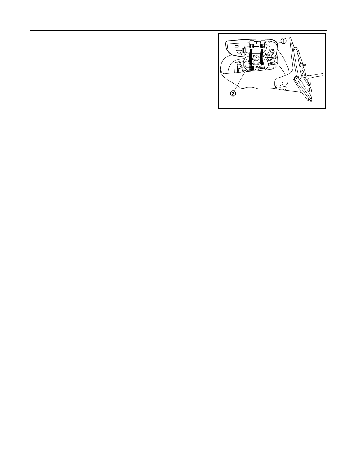
DOOR MIRROR
Revision: October 2006
2007 G35 Sedan
< DISASSEMBLY AND ASSEMBLY >
3. Connect two terminals of heater installed mirror.
4. Fit the upper two pawls on the mirror face (1) onto the mirror
holder bracket (2) first, then press the lower side of mirror face
until a click sound is heard to engage the lower pawls.
NOTE:
After installation, visually check that lower two pawls are
securely engaged from the bottom of mirror face.
[WITH ADP]
PIIB3306J
MIR-70
Page 71

< BASIC INSPECTION >
Revision: October 2006
2007 G35 Sedan
DIAGNOSIS AND REPAIR WORKFLOW
[WITHOUT ADP]
BASIC INSPECTION
DIAGNOSIS AND REPAIR WORKFLOW
Work Flow INFOID:0000000000962356
DETAILED FLOW
1.OBTAIN INFORMATION ABOUT SYMPTOM
Interview the customer to obtain the malfunction information (conditions and environment when the malfunction occurred) as much as possible when the customer brings the vehicle in.
>> GO TO 2.
2.REPRODUCE THE MALFUNCTION INFORMATION
Check the malfunction on the vehicle that the customer describes.
Inspect the relation of the symptoms and the condition when the symptoms occur.
>> GO TO 3.
3.PERFORM “BASIC INSPECTION”
Perform the basic inspection.Refer to MIR-95, "
>> GO TO 4.
4.IDENTIFY THE MALFUNCTIONING SYSTEM WITH “SYMPTOM DIAGNOSIS”
Basic Inspection".
A
B
C
D
E
F
G
H
Use “Symptom diagnosis” from the symptom inspection result in step 2. Then identify where to start performing the diagnosis based on possible causes and symptoms.
>> GO TO 5.
5.IDENTIFY MALFUNCTIONING PARTS WITH “COMPONENT DIAGNOSIS”
Perform the diagnosis with “Component diagnosis” of the applicable system.
>> GO TO 6.
6.REPAIR OR REPLACE THE MALFUNCTIONING PARTS
Repair or replace the specified malfunctioning parts.
>> GO TO 7.
7.FINAL CHECK
Check that malfunctions are not reproduced when obtaining the malfunction information from the customer,
referring to the symptom inspection result in step 2.
Is the malfunctioning part repaired or replaced?
YES >> Trouble diagnosis is completed.
NO >> GO TO 3.
I
J
K
MIR
M
N
O
P
MIR-71
Page 72

DOOR MIRROR SYSTEM
Revision: October 2006
2007 G35 Sedan
< FUNCTION DIAGNOSIS >
[WITHOUT ADP]
FUNCTION DIAGNOSIS
DOOR MIRROR SYSTEM
Component Description INFOID:0000000000962357
Component Function
Door mirror remote control switch It supplies power to mirror motor by mirror switch and changeover switch.
Door mirror
It makes mirror face operate from side to side and up and down with the
mirror control switch operation.
MIR-72
Page 73
< FUNCTION DIAGNOSIS >
Revision: October 2006
2007 G35 Sedan
INSIDE MIRROR SYSTEM
[WITHOUT ADP]
INSIDE MIRROR SYSTEM
System Description INFOID:0000000000962358
It senses the brightness of the headlight of the vehicle to the rear with the sensor integrated into the mirror. It
automatically changes the light transmittance according to the sensed brightness of the light from the headlight.
Component Description INFOID:0000000000962359
Component Function
Auto anti-dazzling inside mirror
It automatically changes the light tran smitt ance accordi ng to the bri ghtness of the
light from the headlight of the vehicle to the rear.
A
B
C
D
E
F
G
H
I
J
K
MIR
M
N
O
P
MIR-73
Page 74
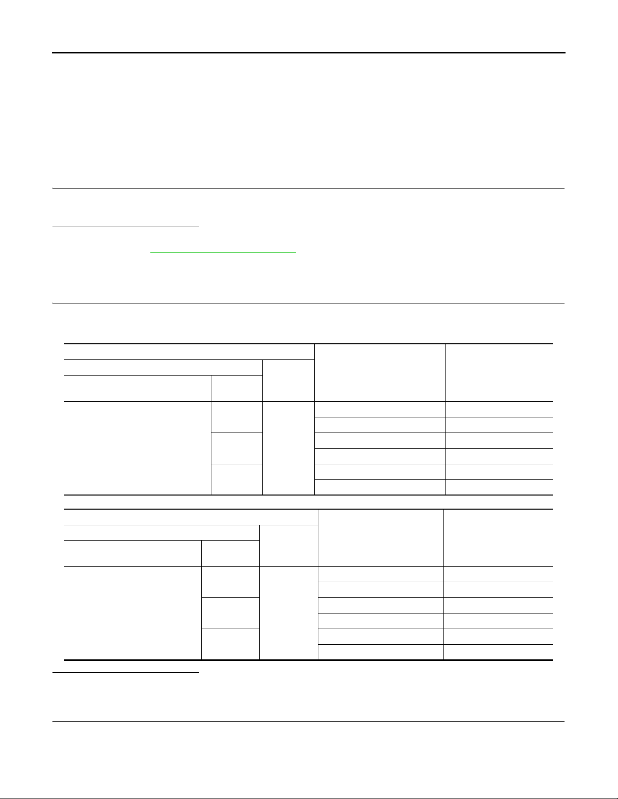
DOOR MIRROR REMOTE CONTROL SWITCH
Revision: October 2006
2007 G35 Sedan
< COMPONENT DIAGNOSIS >
[WITHOUT ADP]
COMPONENT DIAGNOSIS
DOOR MIRROR REMOTE CONTROL SWITCH
Description INFOID:0000000000962360
It supplies electric power to mirror motor by mirror switch and changeover switch.
Component Function Check INFOID:0000000000962361
1.CHECK DOOR MIRROR REMOTE CONTROL SWITCH FUNCTION
1. Turn ignition switch ON.
2. Check that door mirror can operate by door mirror remote control switch operation.
Is the inspection result normal?
YES >> Door mirror remote control switch function is OK.
NO >> Refer to MIR-74, "
Diagnosis Procedure INFOID:0000000000962362
1.CHECK DOOR MIRROR REMOTE CONTROL SWITCH OUTPUT SIGNAL
1. Turn ignition switch ON.
2. Check voltage between mirror control switch connector and ground.
[Driver side]
(+)
Door mirror remote control switch
connector
D7
Diagnosis Procedure".
Terminals
Terminal
10
14
16
(-)
Ground
Mirror switch condition
DOWN / RIGHT Battery voltage
Other than above 0
LEFT Battery voltage
Other than above 0
UP Battery voltage
Other than above 0
Voltage (V)
(Approx.)
[Passenger side]
Door mirror remote control switch
Is the inspection result normal?
YES >> Door mirror remote control switch is OK.
NO >> GO TO 2.
2.CHECK POWER SUPPLY CIRCUIT
1. Turn ignition switch ON.
2. Check voltage between door remote control switch and ground.
connector
D7
(+)
Terminals
Terminal
12
13
15
(-)
Ground
MIR-74
Mirror switch condition
DOWN / RIGHT Battery voltage
Other than above 0
LEFT Battery voltage
Other than above 0
UP Battery voltage
Other than above 0
Voltage (V)
(Approx.)
Page 75
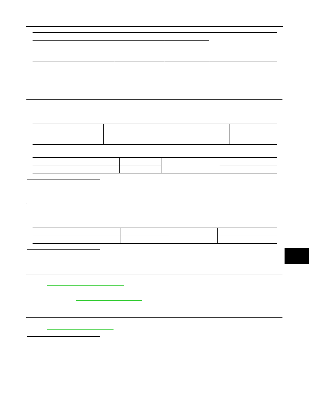
DOOR MIRROR REMOTE CONTROL SWITCH
Revision: October 2006
2007 G35 Sedan
< COMPONENT DIAGNOSIS >
[WITHOUT ADP]
Terminals
(+)
Door mirror remote control switch con-
nector
D7 7 Ground Battery voltage
Terminal
(-)
Is the inspection result normal?
YES >> GO TO 4.
NO >> GO TO 3.
3.CHECK HARNESS CONTINUITY
1. Turn ignition switch OFF.
2. Disconnect door mirror remote control switch connector.
3. Check continuity between mirror control switch connector and fuse block.
Door mirror remote control switch
connector
D7 7 M1 5A Existed
Terminal Fuse block (J/B) Terminal Continuity
4. Check continuity between mirror control switch connector and ground
Door mirror remote control switch connector Terminal
D7 7 Not existed
Ground
Is the inspection result normal?
YES >> GO TO 6.
NO >> Repair or replace harness.
4.CHECK GROUND CIRCUIT
Voltage (V)
(Approx.)
Continuity
A
B
C
D
E
F
G
H
I
1. Turn ignition switch OFF.
2. Disconnect door mirror remote control switch connector.
3. Check continuity between mirror control switch connector and ground.
Door mirror remote control switch connector Terminal
D7 1 Existed
Ground
Is the inspection result normal?
YES >> GO TO 5.
NO >> Repair or replace harness.
5.CHECK DOOR MIRROR REMOTE CONTROL SWITCH
Check door mirror remote control switch.
Refer to MIR-75, "
Component Inspection".
Is the inspection result normal?
YES >> Refer to GI-39, "Intermittent Incident".
NO >> Replace door mirror remote control switch. Refer to MIR-98, "
6.CHECK INTERMITTENT INCIDENT
Check intermittent incident.
Refer to GI-39, "
Is the inspection result normal?
YES >> Check the following.
NO >> Repair or replace the malfunctioning parts.
Intermittent Incident".
• Battery power supply circuit
• Fuse block (J/B)
J
Continuity
K
MIR
M
N
Removal and Installation".
O
P
Component Inspection INFOID:0000000000962363
MIR-75
Page 76
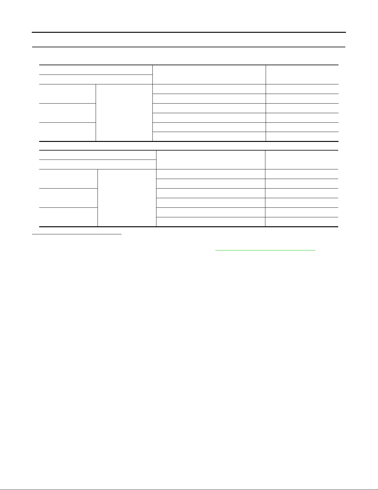
DOOR MIRROR REMOTE CONTROL SWITCH
Revision: October 2006
2007 G35 Sedan
< COMPONENT DIAGNOSIS >
1.CHECK DOOR MIRROR REMOTE CONTROL SWITCH
Check door mirror remote control switch.
[Driver side]
Terminal
Door mirror remote control switch
RIGHT / DOWN Existed
Other than above Not existed
LEFT Existed
Other than above Not existed
UP Existed
Other than above Not existed
RIGHT / DOWN Existed
Other than above Not existed
LEFT Existed
Other than above Not existed
UP Existed
Other than above Not existed
[Passenger side]
Door mirror remote control switch
10
14
16
12
13
15
7
Terminal
7
Is the inspection result normal?
YES >> INSPECTION END.
NO >> Replace door mirror remote control switch. Refer to MIR-98, "
Mirror switch condition Continuity
Mirror switch condition Continuity
[WITHOUT ADP]
Removal and Installation".
MIR-76
Page 77
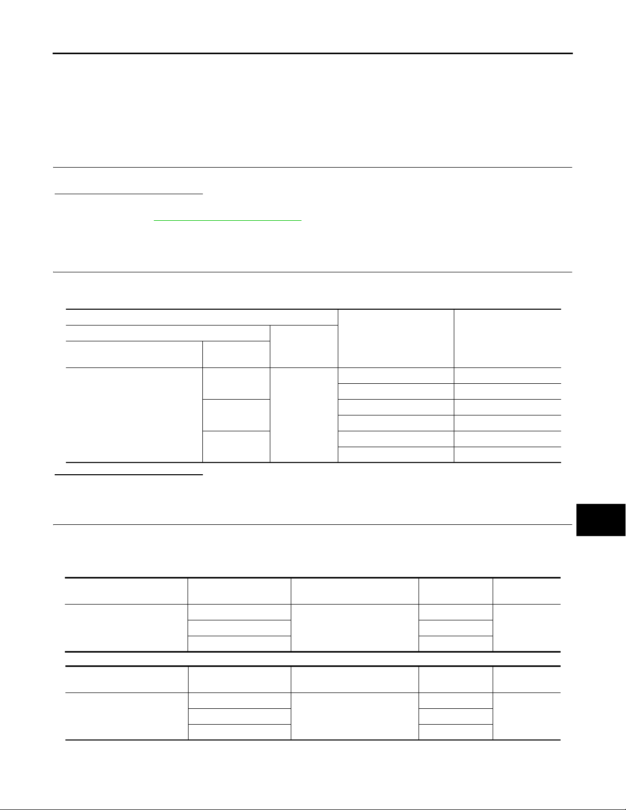
< COMPONENT DIAGNOSIS >
Revision: October 2006
2007 G35 Sedan
DOOR MIRROR MOTOR
[WITHOUT ADP]
DOOR MIRROR MOTOR
Description INFOID:0000000000962364
It supplies electric power to door mirror motor with mirror switch and LH/RH control switch.
Component Function Check INFOID:0000000000962365
1.CHECK DOOR MIRROR MOTOR FUNCTION
Does motor operate normally during mirror switch operation.
Is the inspection result normal?
YES >> Door mirror motor function is OK.
NO >> Refer to MIR-77, "
Diagnosis Procedure".
Diagnosis Procedure INFOID:0000000000962366
1.CHECK DOOR MIRROR MOTOR INPUT SIGNAL
1. Turn ignition switch ON.
2. Check voltage between door mirror connector and ground.
Terminals
(+)
Door mirror
connector
D3 (Driver side)
D33 (Passenger side)
Terminal
5
6
7
(–)
Ground
Mirror switch
Condition
UP Battery voltage
Other than above 0
LEFT Battery voltage
Other than above 0
DOWN / RIGHT Battery voltage
Other than above 0
Voltage (V)
(Approx.)
Is the inspection result normal?
YES >> GO TO 3.
NO >> GO TO 2.
2.CHECK HARNESS CONTINUITY
1. Turn ignition switch OFF.
2. Disconnect door mirror remote control switch connector and door mirror connector.
3. Check continuity between door mirror remote control switch connector and door mirror connector.
- [Driver side]
Door mirror remote control
switch connector
D7
[Passenger side]
Door mirror remote control
switch connector
D7
Terminal
10
14 6
Terminal
12
13 6
- Check continuity between automatic drive positioner control unit connector and ground.
Door mirror (driver side) con-
nector
D3
Door mirror (passenger side)
connector
D33
Terminal Continuity
7
Existed16 5
Terminal Continuity
7
Existed15 5
A
B
C
D
E
F
G
H
I
J
K
MIR
M
N
O
P
MIR-77
Page 78
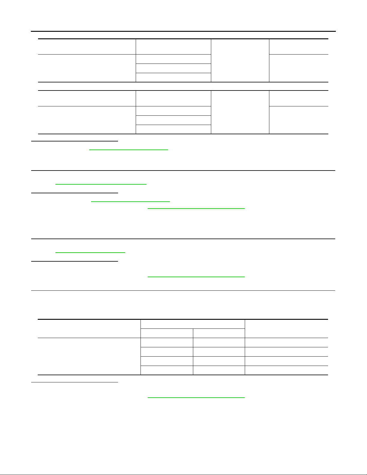
DOOR MIRROR MOTOR
Revision: October 2006
2007 G35 Sedan
< COMPONENT DIAGNOSIS >
[Driver side]
Door mirror remote control switch con-
nector
D7
[Passenger side]
Door mirror remote control switch con-
nector
D7
Is the inspection result normal?
YES >> Refer to GI-39, "Intermittent Incident".
NO >> Repair or replace harness.
3.CHECK DOOR MIRROR MOTOR
Check door mirror motor.
Refer to MIR-78, "
Is the inspection result normal?
YES >> Refer to GI-39, "Intermittent Incident".
NO >> Replace door mirror. Refer to MIR-97, "
Component Inspection".
Terminal
10
14
Terminal
12
13
Removal and Installation".
[WITHOUT ADP]
Continuity
Ground
Not existed16
Continuity
Ground
Not existed15
Component Inspection INFOID:0000000000962367
1.CHECK DOOR MIRROR MOTOR-I
Check that door mirror motor does not trap foreign objects and does not have any damage.
Refer to MIR-97, "
Exploded View".
Is the inspection result normal?
YES >> GO TO 2.
NO >> Replace door mirror. Refer to MIR-97, "
Removal and Installation".
2.CHECK DOOR MIRROR MOTOR-II
1. Turn ignition switch OFF.
2. Disconnect door mirror connector.
3. Apply 12V to each power supply terminal of door mirror motor.
Door mirror connector
D3 (Driver side)
D33 (Passenger side)
Is the inspection result normal?
YES >> INSPECTION END.
NO >> Replace door mirror. Refer to MIR-97, "
(+) (–)
Terminal
76 RIGHT
67 LEFT
57 UP
75 DOWN
Operational direction
Removal and Installation".
MIR-78
Page 79
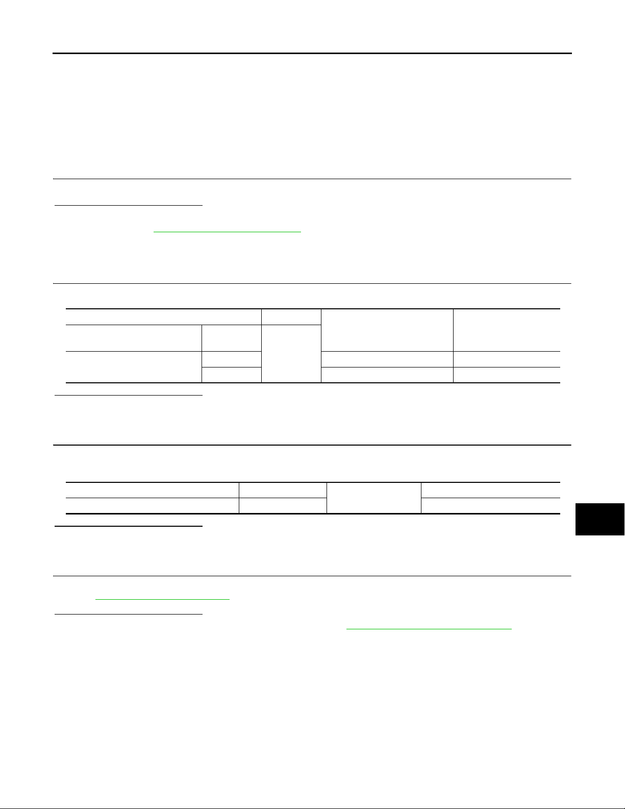
AUTO ANTI-DAZZLING INSIDE MIRROR CIRCUIT
Revision: October 2006
2007 G35 Sedan
< COMPONENT DIAGNOSIS >
[WITHOUT ADP]
AUTO ANTI-DAZZLING INSIDE MIRROR CIRCUIT
Description INFOID:0000000000962368
It automatically changes according to the brightness of the light that is reflected from the headlight of the vehicle to the rear.
Component Function Check INFOID:0000000000962369
1.CHECK AUTO ANTI-DAZZLING INSIDE MIRROR FUNCTION
Check that glare-proof mirror can operate when mirror sensor is illuminated.
Is the inspection result normal?
YES >> Auto anti-dazzling inside mirror function is OK.
NO >> Refer to MIR-79, "
Diagnosis Procedure".
Diagnosis Procedure INFOID:0000000000962370
1.CHECK POWER SUPPLY CIRCUIT
Check voltage between auto anti-dazzling inside mirror connector and ground.
(+) (-)
Auto anti-dazzling inside mirror
connector
R3
Is the inspection result normal?
YES >> GO TO 2.
NO >> Repair or replace harness.
Terminal
Condition of ignition switch
6 ON or START Battery voltage
10 OFF Battery voltage
Ground
Voltage (V)
(Approx.)
2.CHECK GROUND CIRCUIT
1. Disconnect auto anti-dazzling inside mirror connector.
2. Check continuity between auto anti-dazzling inside mirror connector and ground.
Auto anti-dazzling inside mirror connector Terminal
R3 8 Existed
Is the inspection result normal?
YES >> GO TO 3.
NO >> Repair or replace harness.
Ground
Continuity
3.CHECK INTERMITTENT INCIDENT
A
B
C
D
E
F
G
H
I
J
K
MIR
M
Check intermittent incident.
Refer to GI-39, "
Is the inspection result normal?
YES >> Replace auto anti-dazzling inside mirror. Refer to MIR-66, "Removal and Installation".
NO >> Repair or replace the malfunctioning parts.
Intermittent Incident".
N
O
P
MIR-79
Page 80
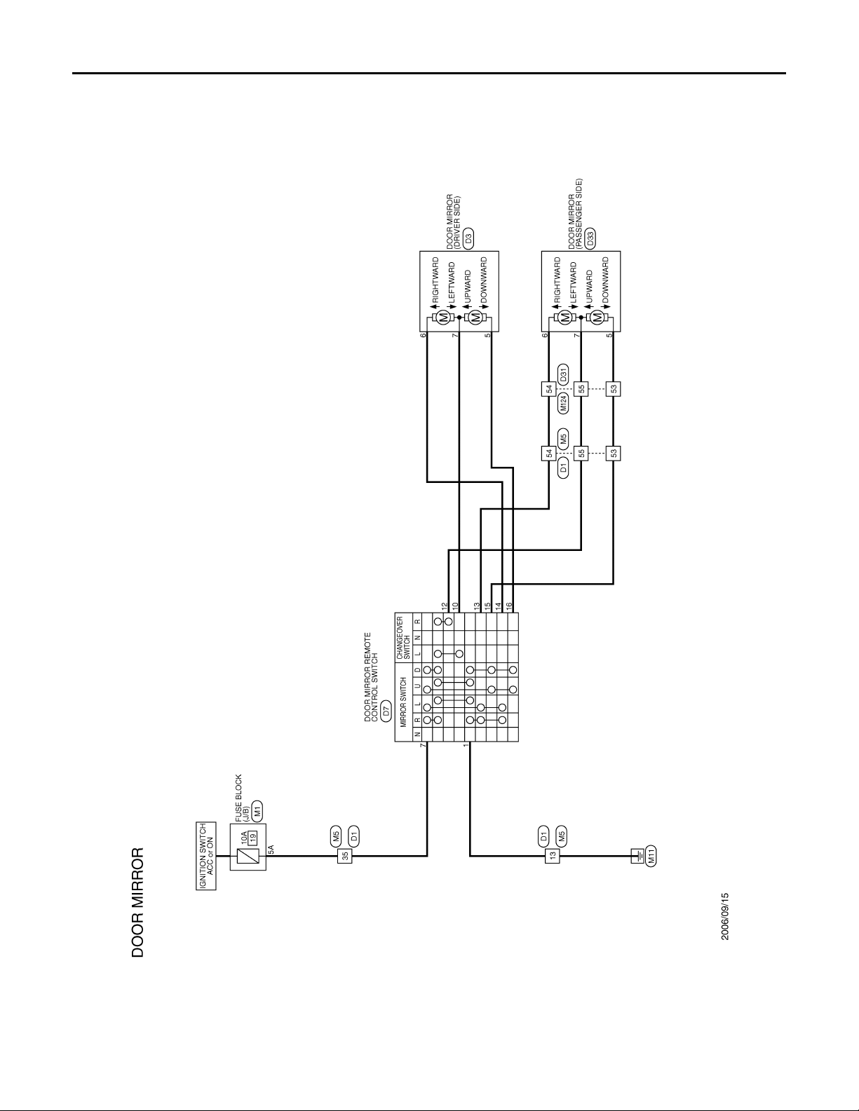
DOOR MIRROR
B
Revision: October 2006
2007 G35 Sedan
< COMPONENT DIAGNOSIS >
[WITHOUT ADP]
DOOR MIRROR
Wiring Diagram —DOOR MIRROR SYSTEM — INFOID:0000000000962371
JCLWA0001G
MIR-80
Page 81
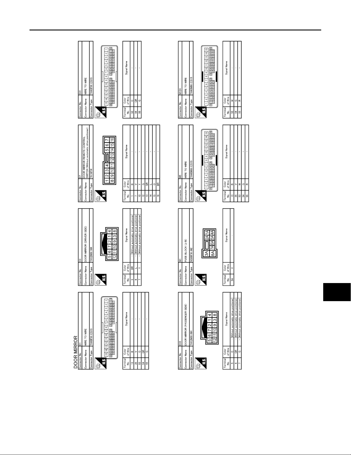
< COMPONENT DIAGNOSIS >
B
Revision: October 2006
2007 G35 Sedan
DOOR MIRROR
[WITHOUT ADP]
A
B
C
D
E
F
G
H
I
J
K
MIR
M
N
O
JCLWA0002G
P
MIR-81
Page 82
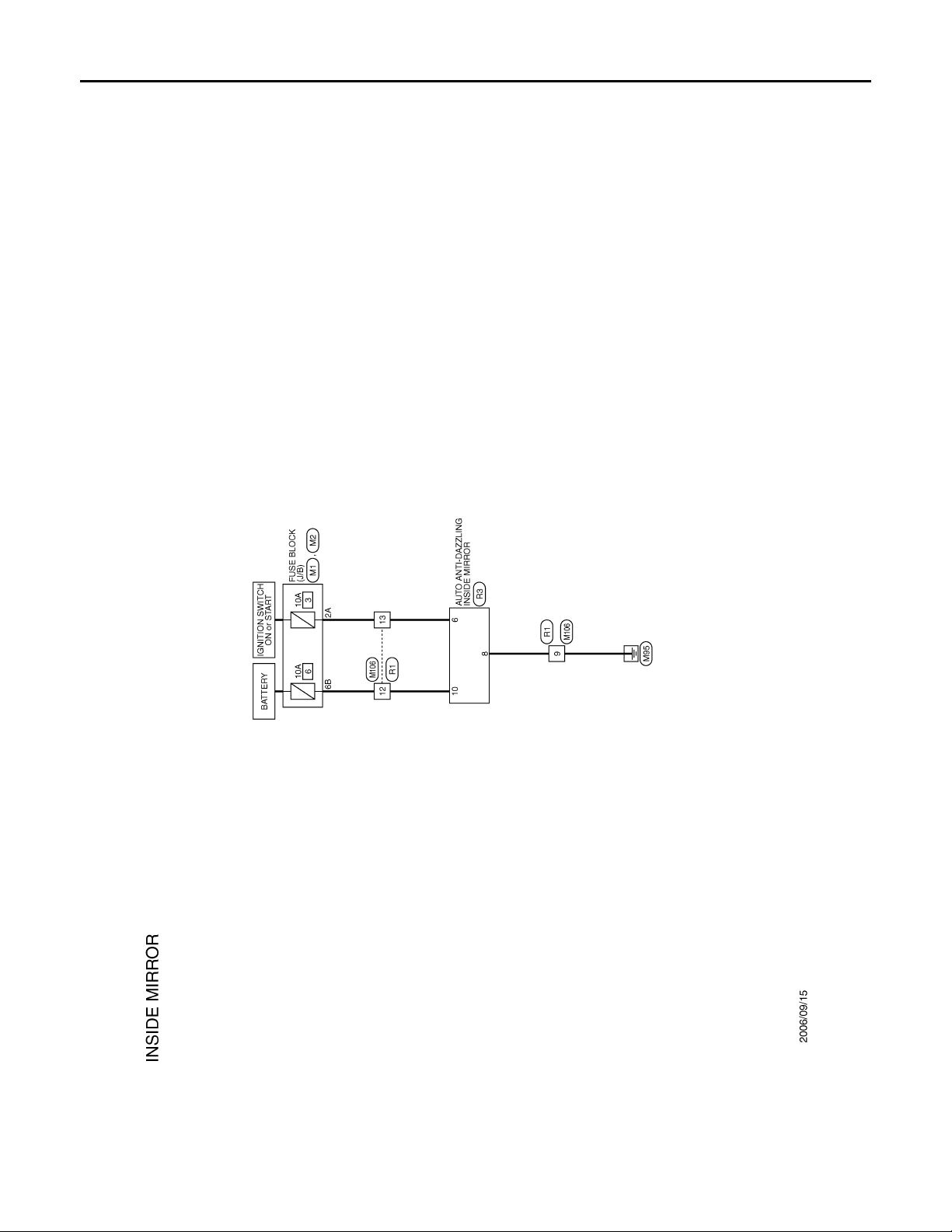
AUTO ANTI-DAZZLING INSIDE MIRROR SYSTEM
B
Revision: October 2006
2007 G35 Sedan
< COMPONENT DIAGNOSIS >
[WITHOUT ADP]
AUTO ANTI-DAZZLING INSIDE MIRROR SYSTEM
Wiring Diagram — INSIDE MIRROR SYSTEM — INFOID:0000000000962372
JCLWA0004G
MIR-82
Page 83
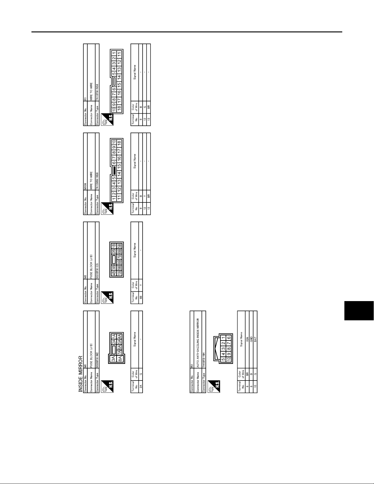
AUTO ANTI-DAZZLING INSIDE MIRROR SYSTEM
B
Revision: October 2006
2007 G35 Sedan
< COMPONENT DIAGNOSIS >
[WITHOUT ADP]
A
B
C
D
E
F
G
H
I
J
K
MIR
M
N
O
JCLWA0005G
P
MIR-83
Page 84

NONE OF THE DOOR MIRROR CAN BE OPERATED USING ANY SWITCH
Revision: October 2006
2007 G35 Sedan
< SYMPTOM DIAGNOSIS >
[WITHOUT ADP]
SYMPTOM DIAGNOSIS
NONE OF THE DOOR MIRROR CAN BE OPERA TED USING ANY SWITCH
Diagnosis Procedure INFOID:0000000000962373
1.CHECK DOOR MIRROR REMOTE CONTROL SWITCH
Check door mirror remote control switch.
Refer to MIR-74, "
Is the inspection result normal?
YES >> Refer to GI-39, "Intermittent Incident".
NO >> Repair or replace the malfunctioning parts.
Component Function Check".
MIR-84
Page 85

< SYMPTOM DIAGNOSIS >
Revision: October 2006
2007 G35 Sedan
DOOR MIRROR DOES NOT OPERATE
[WITHOUT ADP]
DOOR MIRROR DOES NOT OPERATE
Diagnosis Procedure INFOID:0000000000962374
1.CHECK DOOR MIRROR REMOTE CONTROL SWITCH
Check door mirror remote control switch.
Refer to MIR-74, "
Is the inspection result normal?
YES >> GO TO 2.
NO >> Repair or replace the malfunctioning parts.
Component Function Check".
2.CHECK DOOR MIRROR MOTOR
Check the door mirror motor operation.
Refer to MIR-77, "
Is the inspection result normal?
YES >> Refer to GI-39, "Intermittent Incident".
NO >> Repair or replace the malfunctioning parts.
Component Function Check".
A
B
C
D
E
F
G
H
I
J
K
MIR
M
N
O
P
MIR-85
Page 86

AUTO ANTI-DAZZLING INSIDE MIRROR DOES NOT OPERATE
Revision: October 2006
2007 G35 Sedan
< SYMPTOM DIAGNOSIS >
[WITHOUT ADP]
AUTO ANTI-DAZZLING INSIDE MIRROR DOES NOT OPERATE
Diagnosis Procedure INFOID:0000000000962375
1.CHECK AUTO ANTI-DAZZLING INSIDE MIRROR
Check auto anti-dazzling inside mirror.
Refer to MIR-79, "
Is the inspection result normal?
YES >> Refer to GI-39, "Intermittent Incident".
NO >> Repair or replace the malfunctioning parts.
Component Function Check".
MIR-86
Page 87
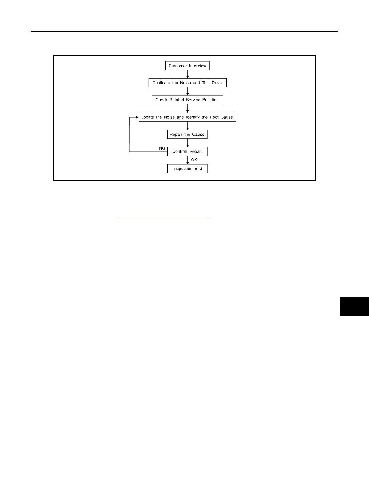
SQUEAK AND RATTLE TROUBLE DIAGNOSES
Revision: October 2006
2007 G35 Sedan
< SYMPTOM DIAGNOSIS >
[WITHOUT ADP]
SQUEAK AND RATTLE TROUBLE DIAGNOSES
Work Flow INFOID:0000000000962376
SBT842
CUSTOMER INTERVIEW
Interview the customer if possible, to determine the conditions that exist when the noise occurs. Use the Diagnostic Worksheet during the interview to document the facts and conditions when the noise occurs and any of
customer's comments; refer to MIR-91, "
conditions that exist when the noise occurs.
• The customer may not be able to provide a detailed description or the location of the noise. Attempt to obtain
all the facts and conditions that exist when the noise occurs (or does not occur).
• If there is more than one noise in the vehicle, perform a diagnosis and repair the noise that the customer is
concerned about. This can be accomplished by performing a cruise test on the vehicle with the customer.
• After identifying the type of noise, isolate the noise in terms of its characteristics. The noise characteristics
are provided so the customer, service adviser and technician are all speaking the same language when
defining the noise.
• Squeak —(Like tennis shoes on a clean floor)
Squeak characteristics include the light contact/fast movement/brought on by road conditions/hard surfaces=higher pitch noise/softer surfaces=lower pitch noises/edge to surface=chirping
• Creak—(Like walking on an old wooden floor)
Creak characteristics include firm contact/slow movement/twisting with a rotational movement/pitch dependent on materials/often brought on by activity.
• Rattle—(Like shaking a baby rattle)
Rattle characteristics include the fast repeated contact/vibration or similar movement/loose parts/missing
clip or fastener/incorrect clearance.
• Knock —(Like a knock on a door)
Knock characteristics include hollow sounding/sometimes repeating/often brought on by driver action.
• Tick—(Like a clock second hand)
Tick characteristics include gentle contacting of light materials/loose components/can be caused by driver
action or road conditions.
• Thump—(Heavy, muffled knock noise)
Thump characteristics include softer knock/dead sound often brought on by activity.
• Buzz—(Like a bumblebee)
Buzz characteristics include high frequency rattle/firm contact.
• Often the degree of acceptable noise level will vary depending up on the person. A noise that you may judge
as acceptable may be very irritating to the customer.
• Weather conditions, especially humidity and temperature, may have a great effect on noise level.
Diagnostic Worksheet". This information is necessary to duplicate the
A
B
C
D
E
F
G
H
I
J
K
MIR
M
N
O
P
DUPLICATE THE NOISE AND TEST DRIVE
If possible, drive the vehicle with the customer until the noise is duplicated. Note any additional information on
the Diagnostic Worksheet regarding the conditions or location of the noise. This information can be used to
duplicate the same conditions when you confirm the repair.
MIR-87
Page 88

SQUEAK AND RATTLE TROUBLE DIAGNOSES
Revision: October 2006
2007 G35 Sedan
< SYMPTOM DIAGNOSIS >
If the noise can be duplicated easily during the test drive, to help identify the source of the noise, try to duplicate the noise with the vehicle stopped by doing one or all of the following:
1) Close a door.
2) Tap or push/pull around the area where the noise appears to be coming from.
3) Rev the engine.
4) Use a floor jack to recreate vehicle “twist”.
5) At idle, apply engine load (electrical load, half-clutch on M/T models, drive position on A/T models).
6) Raise the vehicle on a hoist and hit a tire with a rubber hammer.
• Drive the vehicle and attempt to duplicate the conditions the customer states exist when the noise occurs.
• If it is difficult to duplicate the noise, drive the vehicle slowly on an undulating or rough road to stress the
vehicle body.
CHECK RELATED SERVICE BULLETINS
After verifying the customer concern or symptom, check ASIST for Technical Servic e Bulletins (TSBs) related
to that concern or symptom.
If a TSB relates to the symptom, follow the procedure to repair the noise.
LOCATE THE NOISE AND IDENTIFY THE ROOT CAUSE
1. Narrow down the noise to a general area. To help pinpoint the source of the noise, use a listening tool
(Chassis Ear: J-39570, Engine Ear and mechanics stethoscope).
2. Narrow down the noise to a more specific area and identify the cause of the noise by:
• removing the components in the area that you suspect the noise is coming from.
Do not use too much force when removing clips and fasteners, otherwise clips and fastener can be broken
or lost during the repair, resulting in the creation of new noise.
• tapping or pushing/pulling the component that you suspect is causing the noise.
Do not tap or push/pull the component with excessive force, otherwise the noise will be eliminated only temporarily.
• feeling for a vibration with your hand by touching the component(s) that you suspect is (are) causing the
noise.
• placing a piece of paper between components that you suspect are causing the noise.
• looking for loose components and contact marks.
Refer to MIR-89, "
Inspection Procedure".
[WITHOUT ADP]
REPAIR THE CAUSE
• If the cause is a loose component, tighten the component securely.
• If the cause is insufficient clearance between components:
- separate components by repositioning or loosening and retightening the component, if possible.
- insulate components with a suitable insulator such as urethane pads, foam blocks, felt cloth tape or urethane
tape. A Nissan Squeak and Rattle Kit (J-43980) is available through your authorized Nissan Parts Department.
CAUTION:
Do not use excessive force as many components are constructed of plastic and may be damaged.
NOTE:
Always check with the Parts Department for the latest parts information.
The following materials are contained in the Nissan Squeak and Rattle Kit (J-43980). Each item can be
ordered separately as needed.
URETHANE PADS [1.5 mm (0.059 in) thick]
Insulates connectors, harness, etc.
76268-9E005: 100 × 135 mm (3.94 × 5.31 in)/76884-71L01: 60 × 85 mm (2.36 × 3.35 in)/7688471L02:15 × 25 mm (0.59 × 0.98 in)
INSULATOR (Foam blocks)
Insulates components from contact. Can be used to fill space behind a panel.
73982-9E000: 45 mm (1.77 in) thick, 50 × 50 mm (1.97 × 1.97 in)/7398250Y00: 10 mm (0.39 in) thick, 50 × 50 mm (1.97 × 1.97 in)
INSULATOR (Light foam block)
80845-71L00: 30 mm (1.18 in) thick, 30 × 50 mm (1.18 × 1.97in)
FELT CLOTHTAPE
Used to insulate where movement does not occur. Ideal for instrument panel applications.
68370-4B000: 15 × 25 mm (0.59 × 0.98 in) pad/68239-13E00: 5 mm (0.20 in) wide tape roll
The following materials, not found in the kit, can also be used to repair squeaks and rattles.
UHMW (TEFLON) TAPE
MIR-88
Page 89

SQUEAK AND RATTLE TROUBLE DIAGNOSES
Revision: October 2006
2007 G35 Sedan
< SYMPTOM DIAGNOSIS >
Insulates where slight movement is present. Ideal for instrument panel applications.
SILICONE GREASE
Used in place of UHMW tape that will be visible or not fit. Will only last a few months.
SILICONE SPRAY
Use when grease cannot be applied.
DUCT TAPE
Use to eliminate movement.
[WITHOUT ADP]
A
B
CONFIRM THE REPAIR
Confirm that the cause of a noise is repaired by test driving the vehicle.Operate the vehicle under the same
conditions as when the noise originally occurred. Refer to the notes on the Diagnostic Worksheet.
Inspection Procedure INFOID:0000000000962377
Refer to Table of Contents for specific component removal and installationinformation.
INSTRUMENT PANEL
Most incidents are caused by contact and movement between:
1. The cluster lid A and instrument panel
2. Acrylic lens and combination meter housing
3. Instrument panel to front pillar garnish
4. Instrument panel to windshield
5. Instrument panel mounting pins
6. Wiring harnesses behind the combination meter
7. A/C defroster duct and duct joint
These incidents can usually be located by tapping or moving the components to duplicate the noise or by
pressing on the components while driving to stop the noise. Most of these incidents can be repaired by
applying felt cloth tape or silicon spray (in hard to reach areas). Urethane pads can be used to insulate
wiring harness.
CAUTION:
Do not use silicone spray to isolate a squeak or rattle. If you saturatethe area with silicone, you
will not be able to recheck the repair.
CENTER CONSOLE
Components to pay attention to include:
1. Shifter assembly cover to finisher
2. A/C control unit and cluster lid C
3. Wiring harnesses behind audio and A/C control unit
The instrument panel repair and isolation procedures also apply to thecenter console.
C
D
E
F
G
H
I
J
K
MIR
DOORS
Pay attention to the:
1. Finisher and inner panel making a slapping noise
2. Inside handle escutcheon to door finisher
3. Wiring harnesses tapping
4. Door striker out of alignment causing a popping noise on startsand stops
Tapping or moving the components or pressing on them while driving to duplicate the conditions can isolate
many of these incidents. You can usually insulate the areas with felt cloth tape or insulator foam blocks from
the Nissan Squeak and Rattle Kit (J-43980) to repair the noise.
TRUNK
Trunk noises are often caused by a loose jack or loose items put intothe trunk by the owner.
In addition look for:
1. Trunk lid dumpers out of adjustment
2. Trunk lid striker out of adjustment
3. The trunk lid torsion bars knocking together
4. A loose license plate or bracket
M
N
O
P
MIR-89
Page 90

SQUEAK AND RATTLE TROUBLE DIAGNOSES
Revision: October 2006
2007 G35 Sedan
< SYMPTOM DIAGNOSIS >
Most of these incidents can be repaired by adjusting, securing or insulatingthe item(s) or component(s) causing the noise.
SUNROOF/HEADLINING
Noises in the sunroof/headlining area can often be traced to one of the following:
1. Sunroof lid, rail, linkage or seals making a rattle or light knockingnoise
2. Sunvisor shaft shaking in the holder
3. Front or rear windshield touching headlining and squeaking
Again, pressing on the components to stop the noise while duplicatingthe conditions can isolate most of these
incidents. Repairs usually consistof insulating with felt cloth tape.
SEATS
When isolating seat noise it's important to note the position the seatis in and the load placed on the seat when
the noise is present. These conditionsshould be duplicated when verifying and isolating the cause of the
noise.
Cause of seat noise include:
1. Headrest rods and holder
2. A squeak between the seat pad cushion and frame
3. The rear seatback lock and bracket
These noises can be isolated by moving or pressing on the suspectedcomponents while duplicating the condi-
tions under which the noise occurs.Most of these incidents can be repaired by repositioning the component
orapplying urethane tape to the contact area.
[WITHOUT ADP]
UNDERHOOD
Some interior noise may be caused by components under the hood or onthe engine wall. The noise is then
transmitted into the passenger compartment.
Causes of transmitted underhood noise include:
1. Any component mounted to the engine wall
2. Components that pass through the engine wall
3. Engine wall mounts and connectors
4. Loose radiator mounting pins
5. Hood bumpers out of adjustment
6. Hood striker out of adjustment
These noises can be difficult to isolate since they cannot be reached from the interior of the vehicle. The best
method is to secure, move or insulate one component at a time and test drive the vehicle. Also, engine RPM
or load can be changed to isolate the noise. Repairs can usually be made by moving, adjusting, securing, or
insulating the component causing the noise.
MIR-90
Page 91
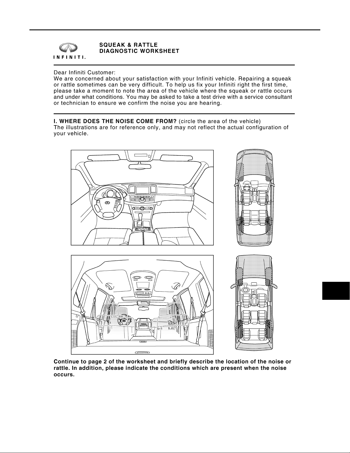
SQUEAK AND RATTLE TROUBLE DIAGNOSES
Revision: October 2006
2007 G35 Sedan
< SYMPTOM DIAGNOSIS >
[WITHOUT ADP]
Diagnostic Worksheet INFOID:0000000000962378
A
B
C
D
E
F
G
H
I
J
K
MIR
M
N
O
PIIB8741E
P
MIR-91
Page 92
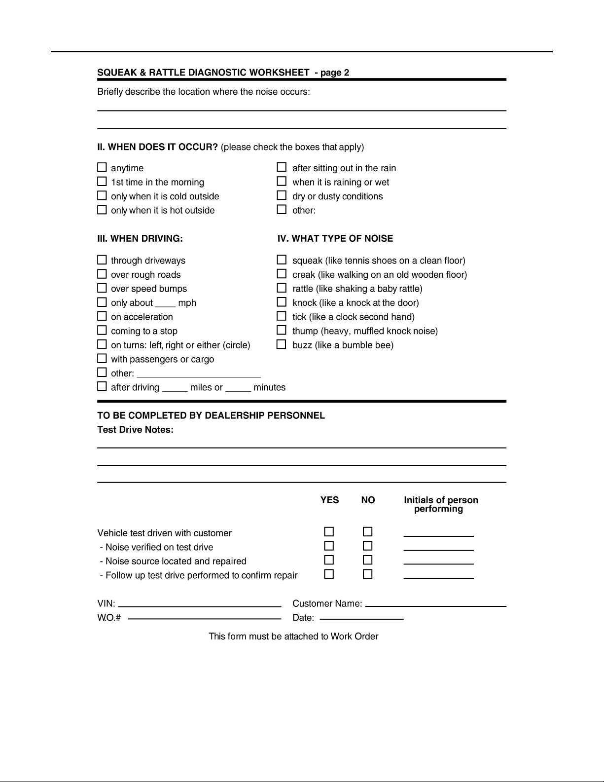
SQUEAK AND RATTLE TROUBLE DIAGNOSES
Revision: October 2006
2007 G35 Sedan
< SYMPTOM DIAGNOSIS >
[WITHOUT ADP]
PIIB8742E
MIR-92
Page 93

< PRECAUTION >
Revision: October 2006
2007 G35 Sedan
PRECAUTIONS
[WITHOUT ADP]
PRECAUTION
PRECAUTIONS
Precaution for Supplemental Restraint System (SRS) "AIR BAG" and "SEAT BELT PRE-TENSIONER" INFOID:0000000000962379
The Supplemental Restraint System such as “AIR BAG” and “SEAT BELT PRE-TENSIONER”, used along
with a front seat belt, helps to reduce the risk or severity of injury to the driver and front passenger for certain
types of collision. This system includes seat belt switch inputs and dual stage front air bag modules. The SRS
system uses the seat belt switches to determine the front air bag deployment, and may only deploy one front
air bag, depending on the severity of a collision and whether the front occupants are belted or unbelted.
Information necessary to service the system safely is included in the SRS and SB section of this Service Manual.
WARNING:
• To avoid rendering the SRS inoperative, which could increase the risk of personal injury or death in
the event of a collision which would result in air bag inflation, all maintenance must be performed by
an authorized NISSAN/INFINITI dealer.
• Improper maintenance, including incorrect removal and installation of the SRS, can lead to personal
injury caused by unintentional activation of the system. For removal of Spiral Cable and Air Bag
Module, see the SRS section.
• Do not use electrical test equipment on any circuit related to the SRS unless instructed to in this
Service Manual. SRS wiring harnesses can be identified by yellow and/or orange harnesses or harness connectors.
A
B
C
D
E
F
G
H
I
J
K
MIR
M
N
O
P
MIR-93
Page 94
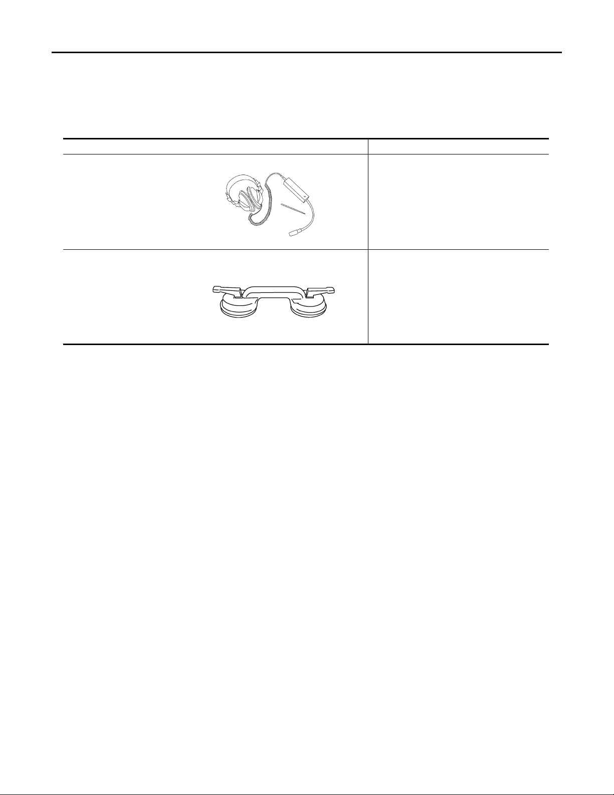
PREPARATION
Revision: October 2006
2007 G35 Sedan
< PREPARATION >
[WITHOUT ADP]
PREPARATION
PREPARATION
Commercial Service Tools INFOID:0000000000962380
Tool name Description
Engine ear Locating the noise
SIIA0995E
Suction lifter Holding the door glass
PIIB1805J
MIR-94
Page 95

PRE-INSPECTION FOR DIAGNOSTIC
Revision: October 2006
2007 G35 Sedan
< ON-VEHICLE MAINTENANCE >
[WITHOUT ADP]
ON-VEHICLE MAINTENANCE
PRE-INSPECTION FOR DIAGNOSTIC
Basic Inspection INFOID:0000000000962381
BASIC INSPECTION
1.INSPECTION START
1. Check the service history.
2. Check the following parts.
• Fuse/circuit breaker blown.
• Poor connection, open or short circuit of harness connector.
• Battery voltage.
Is the inspection result normal?
YES >> Inspection end.
NO >> Repair or replace the malfunctioning parts.
A
B
C
D
E
F
G
H
I
J
K
MIR
M
N
O
P
MIR-95
Page 96
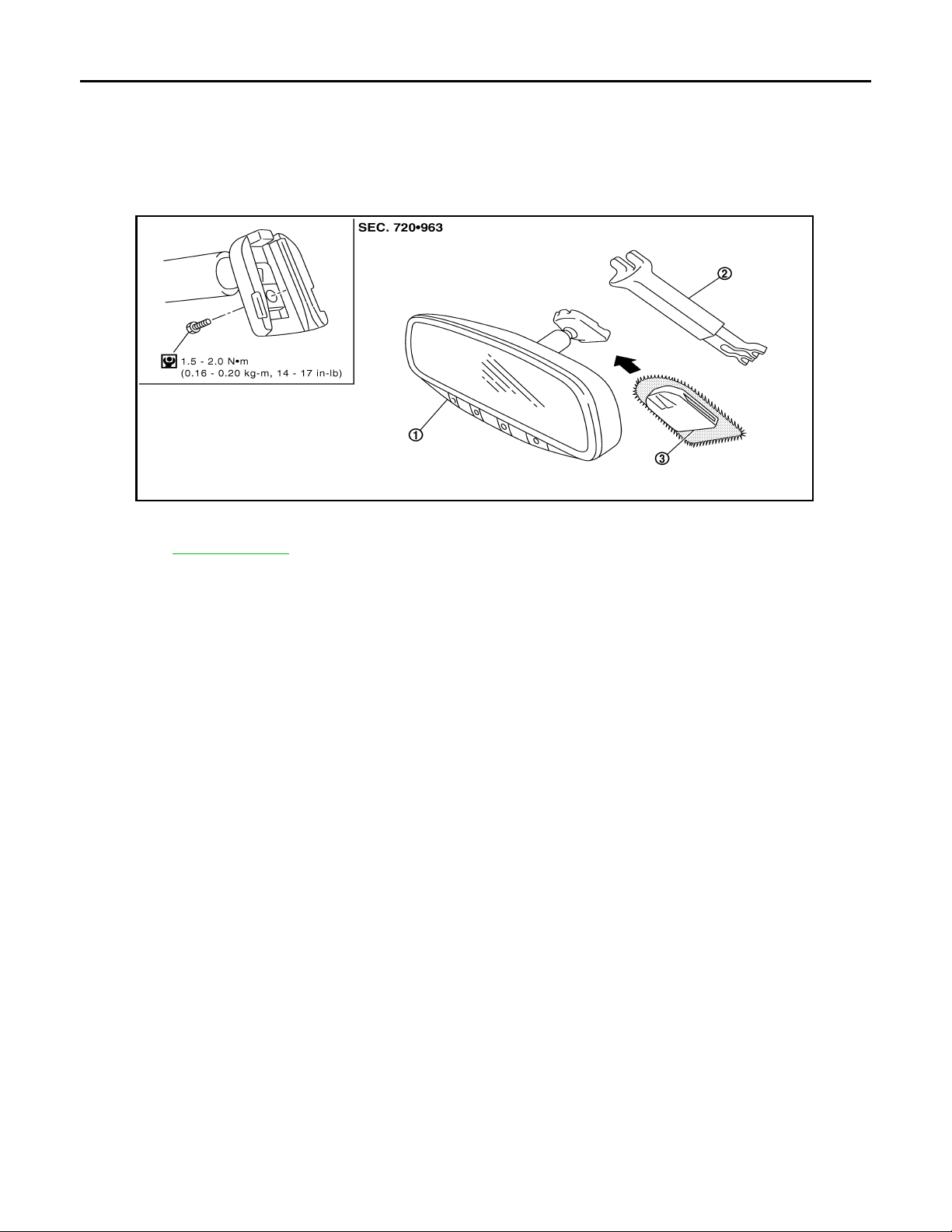
INSIDE MIRROR
Revision: October 2006
2007 G35 Sedan
< ON-VEHICLE REPAIR >
[WITHOUT ADP]
ON-VEHICLE REPAIR
INSIDE MIRROR
Exploded View INFOID:0000000000962382
PIIB5780E
1. Inside mirror 2. Inside mirror finisher (if equipped) 3. Mirror base
Refer to GI-4, "
Components" for symbols in the figure.
Removal and Installation INFOID:0000000000962383
REMOVAL
1. Remove inside mirror finisher (if equipped).
2. Remove nut of mirror base.
3. Slide the mirror upward to remove.
4. Disconnect the connector (if equipped).
INSTALLATION
Install in the reverse order of removal.
MIR-96
Page 97
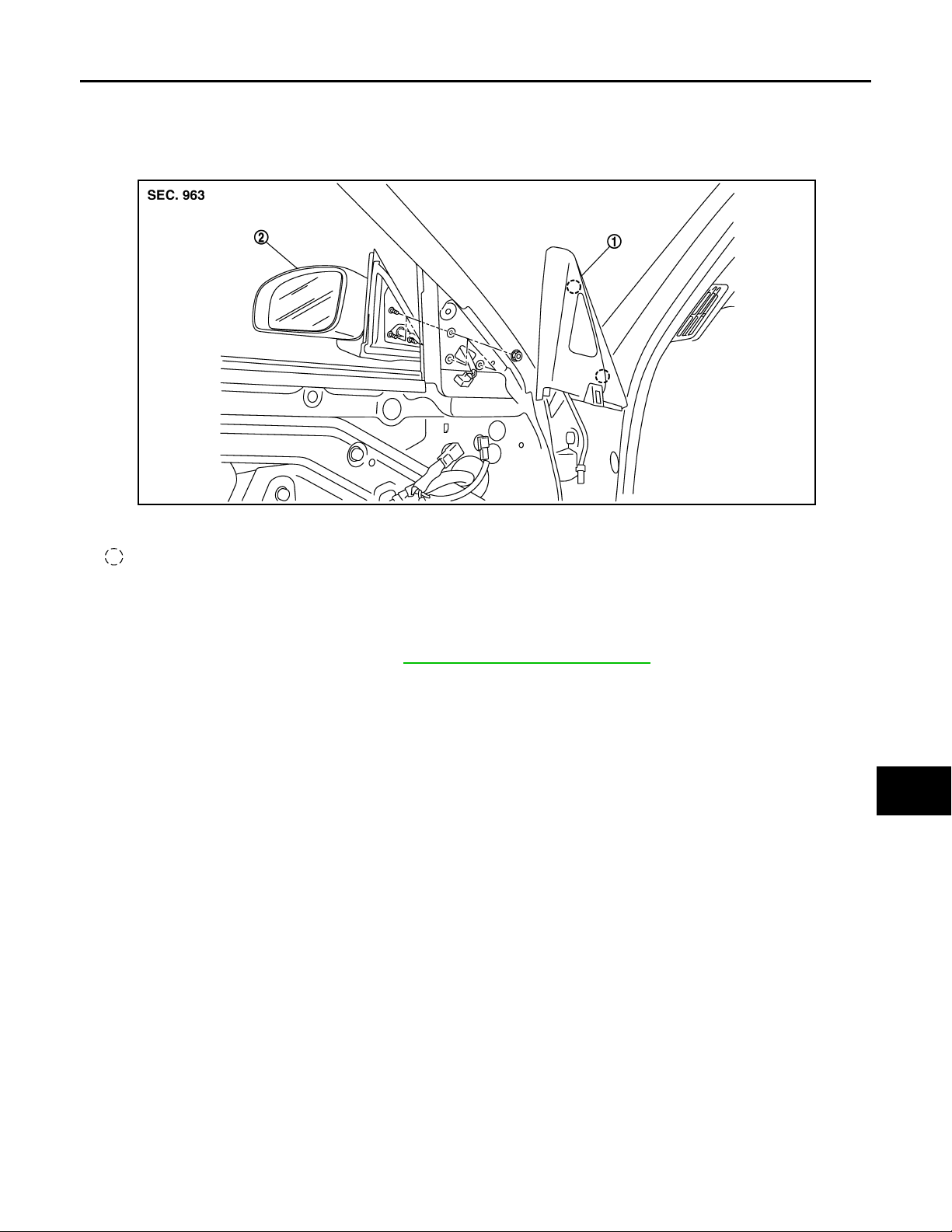
< ON-VEHICLE REPAIR >
Revision: October 2006
2007 G35 Sedan
DOOR MIRROR
[WITHOUT ADP]
DOOR MIRROR
Exploded View INFOID:0000000000962384
JMLIA0001ZZ
1. Corner cover 2. Door mirror assembly
Clip
A
B
C
D
E
F
G
H
Removal and Installation INFOID:0000000000962385
REMOVAL
1. Remove the front door finisher. Refer to INT-10, "Removal and Installation".
2. Remove the corner cover.
3. Disconnect the door mirror harness connector.
4. Remove the door mirror mounting nuts, and remove the door mirror assembly.
CAUTION:
Do not damage the mirror bodies.
INSTALLATION
Install in the reverse order of removal.
CAUTION:
Do not damage the mirror bodies.
I
J
K
MIR
M
N
O
P
MIR-97
Page 98
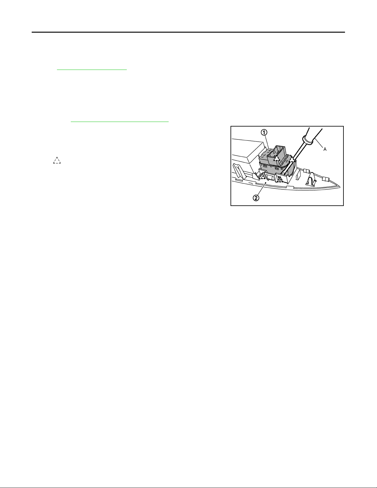
DOOR MIRROR REMOTE CONTROL SWITCH
Revision: October 2006
2007 G35 Sedan
< ON-VEHICLE REPAIR >
[WITHOUT ADP]
DOOR MIRROR REMOTE CONTROL SWITCH
Exploded View INFOID:0000000000962386
Refer to INT-10, "Exploded View".
Removal and Installation INFOID:0000000000962387
REMOVAL
1. Remove the power window main switch finisher (2).
Refer to INT-10, "
2. Remove door mirror remote control switch (1) from power window main switch finisher (2) using screw driver (A).
Removal and Installation".
: Pawl
INSTALLATION
Install in the reverse order of removal.
JMLIA0011ZZ
MIR-98
Page 99
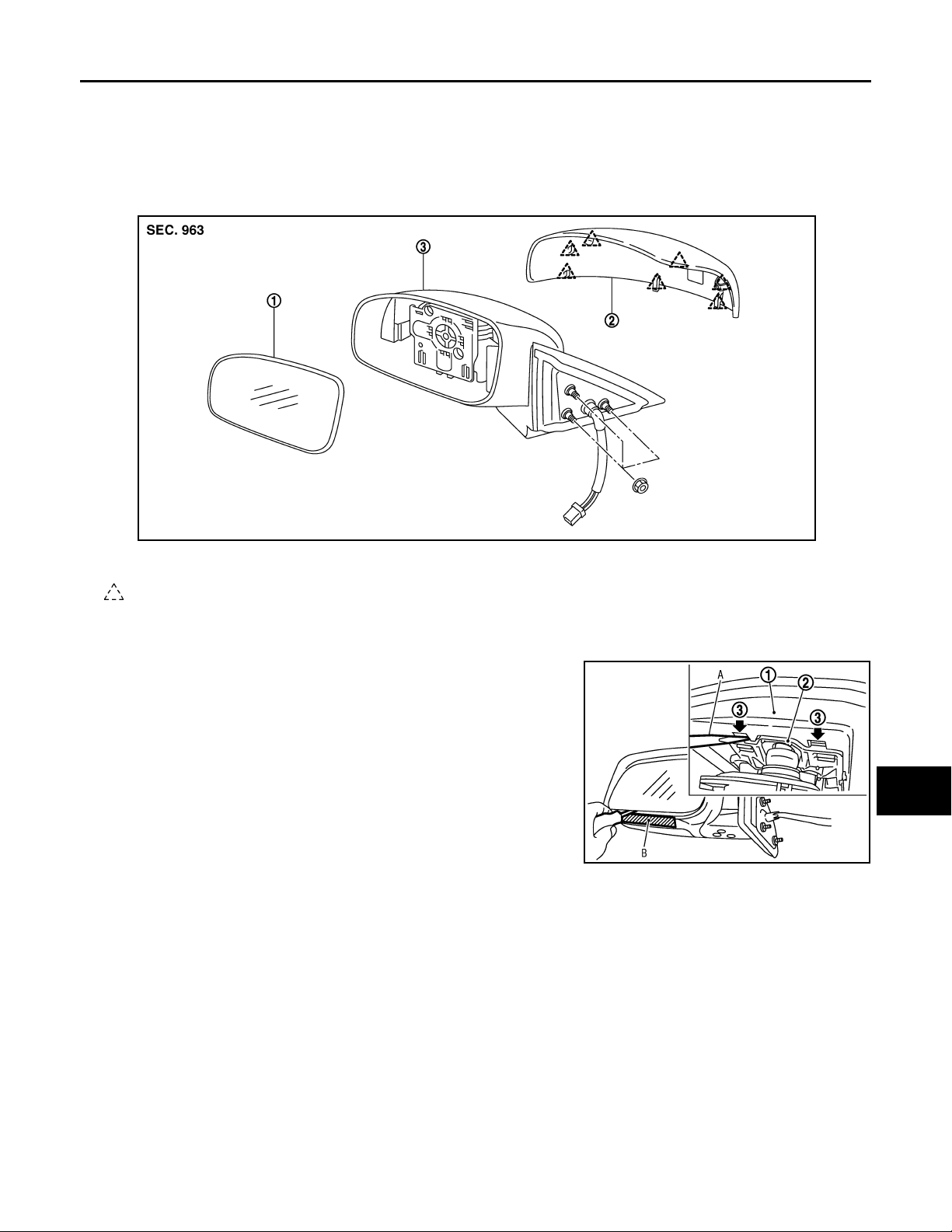
< DISASSEMBLY AND ASSEMBLY >
Revision: October 2006
2007 G35 Sedan
DOOR MIRROR
[WITHOUT ADP]
DISASSEMBLY AND ASSEMBLY
DOOR MIRROR
Exploded View INFOID:0000000000962388
JMLIA0002ZZ
1. Mirror (mirror holder) 2. Mirror assembly 3. Mirror cover
Pawl
Disassembly INFOID:0000000000962389
A
B
C
D
E
F
G
H
I
1. Place the mirror body with mirror glass facing upward.
2. Put a strip of protective tape B on mirror body.
3. As shown in the figure, insert a small slotted screwdriver A into
the recess between mirror base (mirror holder)(1) and mirror
holder bracket (2). Push up two pawls (3) to remove mirror
holder lower half side.
NOTE:
When pushing up pawls do not attempt to use one recess only,
be sure to push up with both recesses.
Insert screwdriver into recesses, and push up while rotating
(twisting) to make work easier.
4. Remove two terminals of mirror heater attachment.
5. Lightly lift up lower side of mirror surface from mirror surface, and detach two pawls of upper side as if
pulling it out. Remove mirror surface from mirror body .
NOTE:
Be careful not to allow grease on sealing agent in center of mirror body assembly (actuator) or back side
of mirror surface (mirror holder).
6. Remove the clips and mirror cover from the housing.
PIIB8320J
Assembly INFOID:0000000000962390
1. Install the mirror cover.
2. Place mirror holder bracket and mirror body assembly (actuator) in a horizontal position.
J
K
MIR
M
N
O
P
MIR-99
Page 100
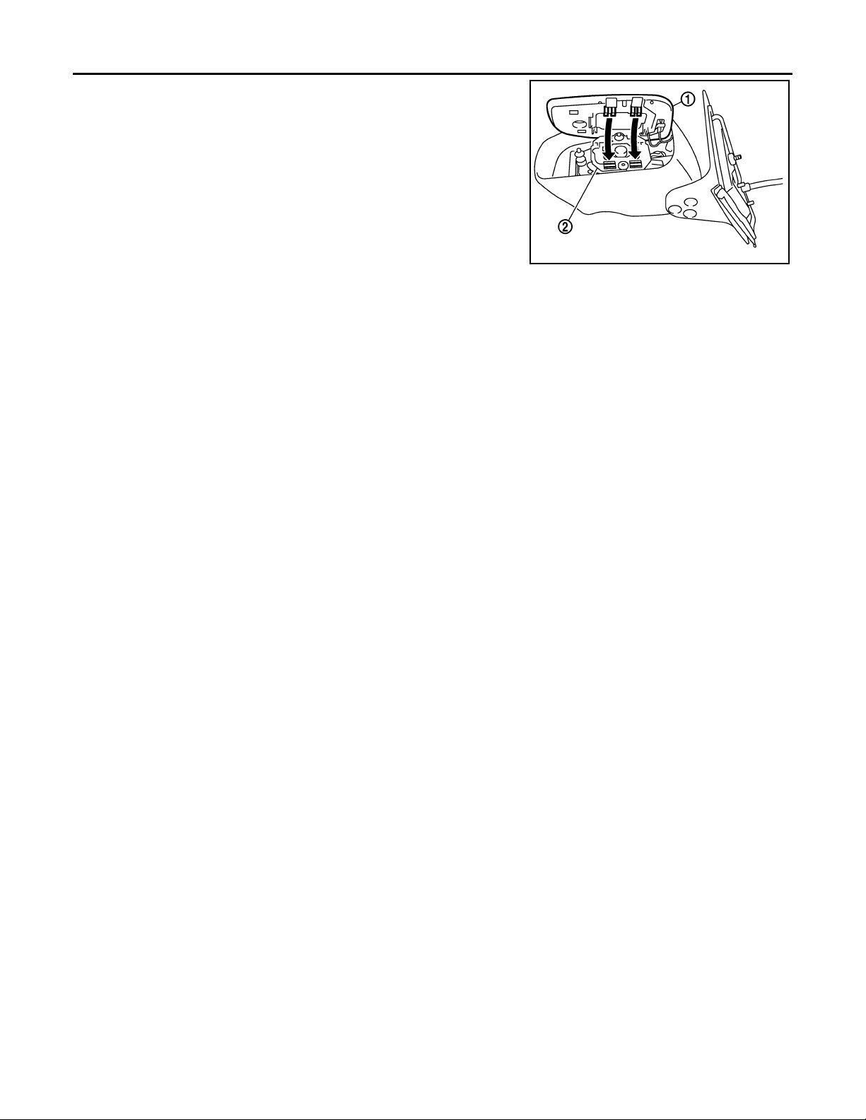
DOOR MIRROR
Revision: October 2006
2007 G35 Sedan
< DISASSEMBLY AND ASSEMBLY >
3. Connect two terminals of heater installed mirror.
4. Fit the upper two pawls on the mirror face (1) onto the mirror
holder bracket (2) first, then press the lower side of mirror face
until a click sound is heard to engage the lower pawls.
NOTE:
After installation, visually check that lower two pawls are
securely engaged from the bottom of mirror face.
[WITHOUT ADP]
PIIB3306J
MIR-100
 Loading...