

Datasheet MIC5250-3.0BMM, MIC5250-3.3BMM, MIC5250-2.7BMM, MIC5250-2.8BMM Datasheet (MICREL)
Page 1
MIC5250 Micrel
MIC5250
Dual 150mA µCap CMOS LDO Regulator
Preliminary Information
General Description
The MIC5250 is an efficient, precise dual CMOS voltage
regulator optimized for ultra-low-noise applications. The
MIC5250 offers better than 1% initial accuracy, extremely low
dropout voltage (typically 150mV at 150mA) and constant
ground current over load (typically 100µA). The MIC5250
provides a very-low-noise output, ideal for RF applications
where quiet voltage sources are required. A noise bypass pin
is also available for further reduction of output noise.
Designed specifically for hand-held and battery-powered
devices, the MIC5250 provides TTL logic compatible enable
pins. When disabled, power consumption drops nearly to
zero.
The MIC5250 also works with low-ESR ceramic capacitors,
reducing the amount of board space necessary for power
applications, critical in hand-held wireless devices.
Key features include current limit, thermal shutdown, pushpull outputs for faster transient response, and active clamps
to speed up device turnoff. Available in the 10-lead MSOP
(micro-shrink-outline package), the MIC5250 also offers a
range of fixed output voltages.
Features
• Ultralow dropout—100mV @ 100mA
• Ultralow noise—30µV(rms)
• Stability with ceramic, tantalum, or aluminum electrolytic
capacitors
• Load independent, ultralow ground current
• 150mA output current
• Current limiting
• Thermal Shutdown
• Tight load and line regulation
• “Zero” off-mode current
• Fast transient response
• TTL-Logic-controlled enable input
Applications
• Cellular phones and pagers
• Cellular accessories
• Battery-powered equipment
• Laptop, notebook, and palmtop computers
• PCMCIA VCC and VPP regulation/switching
• Consumer/personal electronics
• SMPS post-regulator/dc-to-dc modules
• High-efficiency linear power supplies
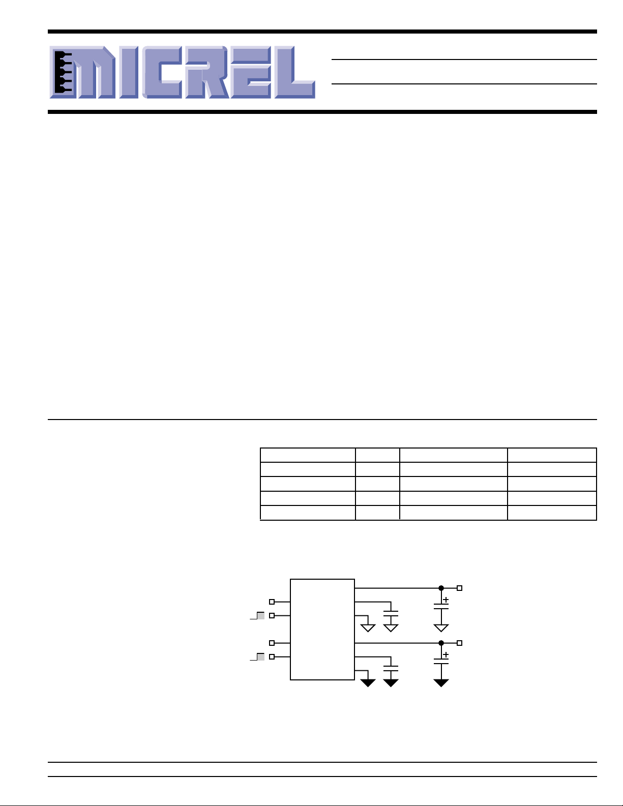
Typical Application
Ordering Information
Part Number Voltage Junction Temp. Range Package
MIC5250-2.7BMM 2.7V –40°C to +125°C 10-lead MSOP
MIC5250-2.8BMM 2.8V –40°C to +125°C 10-lead MSOP
MIC5250-3.0BMM 3.0V –40°C to +125°C 10-lead MSOP
MIC5250-3.3BMM 3.3V –40°C to +125°C 10-lead MSOP
Other voltages available. Contact Micrel for details.
MIC5250-3.3BMM
9
V
ENABLE
SHUTDOWN
ENABLE
SHUTDOWN
ENA may be connected directly to INA.
ENB may be connected directly to INB.
GNDA and GND B may be connected to
isolated grounds or the same ground.
INA
V
INB
INA
2
ENA
7
INB
5
ENB
OUTA
BYPA
GNDA
OUTB
BYPB
GNDB
10
1
C
3
8
4
6
BYPA
(optional)
C
BYPB
(optional)
C
C
3.3V
OUTA
3.3V
OUTB
Dual Ultra-Low-Noise Regulator Circuit
Micrel, Inc. • 1849 Fortune Drive • San Jose, CA 95131 • USA • tel + 1 (408) 944-0800 • fax + 1 (408) 944-0970 • http://www.micrel.com
March 2000 1 MIC5250
Page 2
MIC5250 Micrel
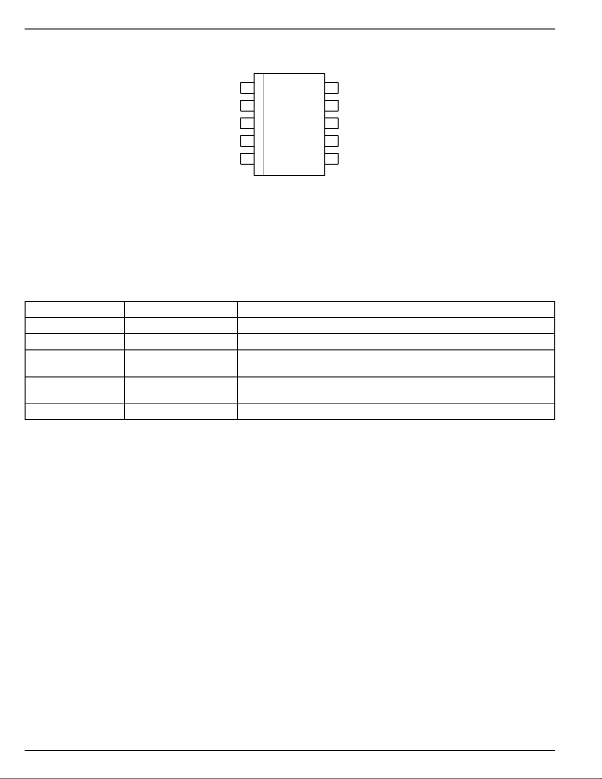
Pin Configuration
ENA
GNDA
BYPB
ENB
Pin Description
Pin Number Pin Name Pin Function
9 / 7 INA / B Supply Input*
3 / 6 GNDA / B Ground*
2 / 4 ENA / B Enable/Shutdown (Input): CMOS compatible input. Logic high = enable;
1 / 4 BYPA / B Reference Bypass: Connect external 0.01µF capacitor to GND to reduce
10 / 8 OUTA / B Regulator Output
* Supply inputs and grounds are fully isolated.
1BYPA
2
3
4
5
10 OUTA
INA
9
OUTB
8
INB
7
GNDB
6
MIC5250-x.xBMM
logic low = shutdown. Do not leave open.
output noise. May be left open.
Absolute Maximum Ratings (Note 1)
Supply Input Voltage (VIN) .................................. 0V to +7V
Enable Input Voltage (VEN) ................................. 0V to +7V
Junction Temperature (TJ) ...................................... +150°C
Storage Temperature ............................... –65°C to +150°C
Operating Ratings (Note 2)
Input Voltage (VIN) ......................................... +2.7V to +6V
Enable Input Voltage (VEN) .................................. 0V to V
Junction Temperature (TJ) ....................... –40°C to +125°C
Thermal Resistance (θJA)......................................200°C/W
IN
Lead Temperature (soldering, 5 sec.) ....................... 260°C
ESD, Note 3
MIC5250 2 March 2000
Page 3
MIC5250 Micrel
Electrical Characteristics
Each regulator: VIN = V
Symbol Parameter Conditions Min Typical Max Units
V
O
∆V
LNR
∆V
LDR
VIN – V
I
Q
I
GND
OUT
Output Voltage Accuracy I
Line Regulation VIN = V
Load Regulation I
Dropout Voltage, Note 5 I
Quiescent Current VEN ≤ 0.4V (shutdown) 0.2 1 µA
Ground Pin Current, Note 6 I
PSRR Power Supply Rejection f = 120Hz, C
I
e
LIM
n
Current Limit V
Output Voltage Noise C
Enable Input
V
IL
V
IH
I
EN
Enable Input Logic-Low Voltage VIN = 2.7V to 5.5V, regulator shutdown 0.8 0.4 V
Enable Input Logic-High Voltage VIN = 2.7V to 5.5V, regulator enabled 2.0 1V
Enable Input Current VIL ≤ 0.4V 0.17 µA
Shutdown Resistance Discharge 500 Ω
Thermal Protection
Thermal Shutdown Temperature 150 °C
Thermal Shutdown Hysteresis 10 °C
+ 1V, VEN = V
OUT
= 100µA; TJ = 25°C, bold values indicate –40°C ≤ TJ ≤ +125°C; unless noted.
IN; IOUT
= 0mA –11%
OUT
–2 2 %
+ 0.1V to 6V –0.3 0 0.3 %/V
OUT
= 0.1mA to 150mA, Note 4 2.0 3.0 %
OUT
= 100µA 1.5 5 mV
OUT
I
= 50mA 50 85 mV
OUT
I
= 100mA 100 150 mV
OUT
I
= 150mA 150 200 mV
OUT
= 0mA 100 150 µA
OUT
I
= 150mA 100 µA
OUT
= 10µF, C
OUT
= 0V 160 300 mA
OUT
= 10µF, C
OUT
f = 10Hz to 100kHz
= 0.01µF, 30
BYP
= 0.01µF50dB
BYP
VIH ≥ 2.0V 1.5 µA
250 mV
µV(rms)
Note 1. Exceeding the absolute maximum rating may damage the device.
Note 2. The device is not guaranteed to function outside its operating rating.
Note 3. Devices are ESD sensitive. Handling precautions recommended.
Note 4. Regulation is measured at constant junction temperature using low duty cycle pulse testing. Parts are tested for load regulation in the load
Note 5. Dropout Voltage is defined as the input to output differential at which the output voltage drops 2% below its nominal value measured at 1V
Note 6. Ground pin current is the regulator quiescent current. The total current drawn from the supply is the sum of the load current plus the ground
range from 0.1mA to 150mA. Changes in output voltage due to heating effects are covered by the thermal regulation specification.
differential.
pin current.
March 2000 3 MIC5250
Page 4
MIC5250 Micrel
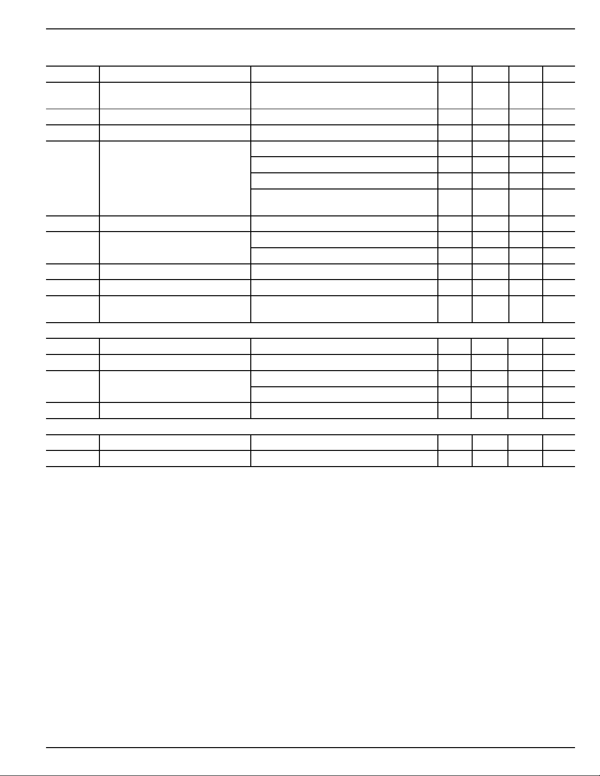
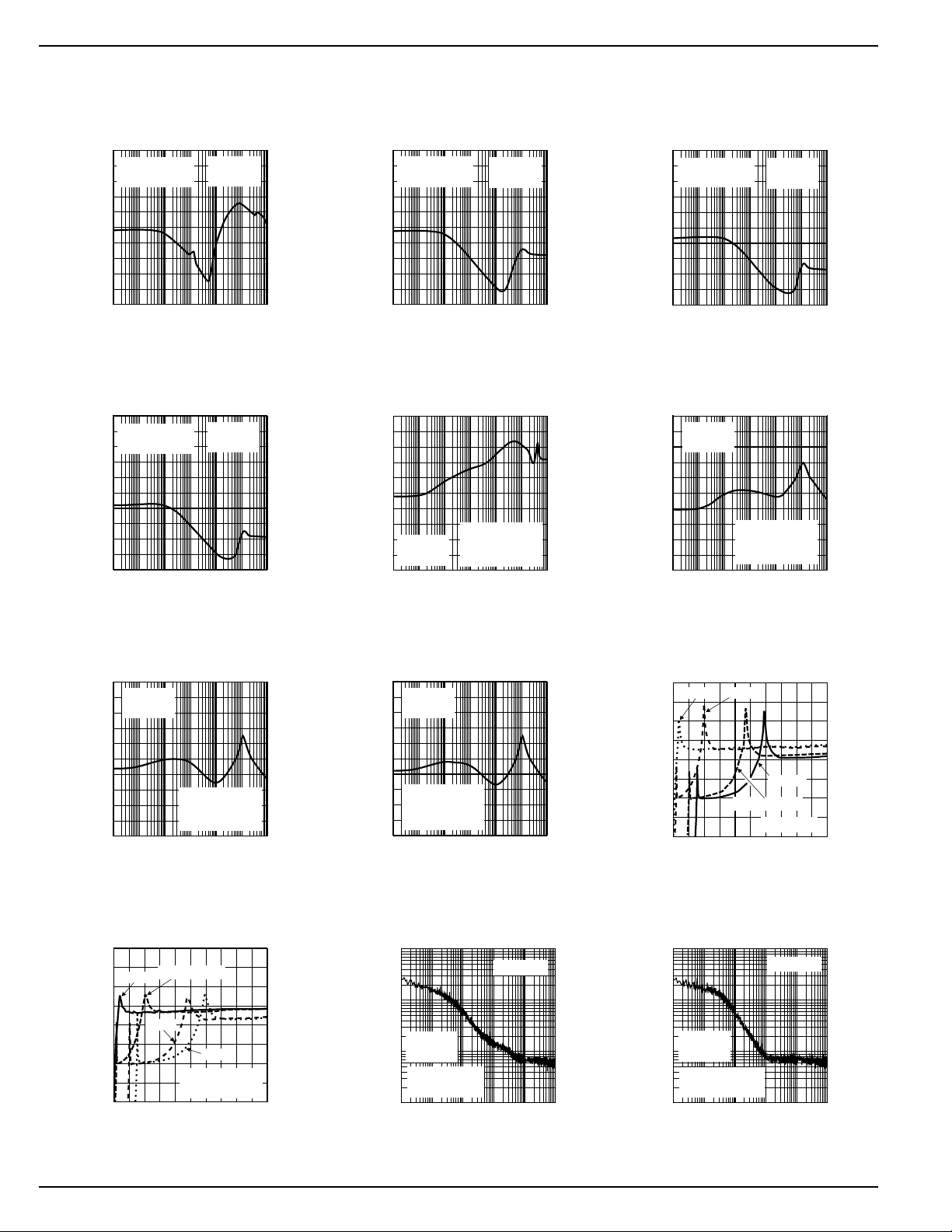
Typical Characteristics
Power Supply
100
80
60
40
PSRR (dB)
20
Rejection Ratio
10k
VIN = 4V
V
OUT
100k
= 3V
1M
I
= 100µA
OUT
C
= 1µF tant
OUT
0
1E+11E+21E+31E+41E+5 1E+6 1E+7
10
1k
100
FREQUENCY (Hz)
Power Supply
100
80
60
40
PSRR (dB)
20
Rejection Ratio
10k
VIN = 4V
V
OUT
100k
= 3V
1M
I
= 150mA
OUT
C
= 1µF tant
OUT
0
1E+11E+21E+31E+41E+5 1E+6 1E+7
10
1k
100
FREQUENCY (Hz)
10M
10M
Power Supply
100
80
60
40
PSRR (dB)
20
Rejection Ratio
I
= 10mA
OUT
C
= 1µF tant
OUT
0
1E+11E+21E+31E+41E+5 1E+6 1E+7
10
1k
100
FREQUENCY (Hz)
10k
VIN = 4V
V
OUT
100k
= 3V
1M
Power Supply
100
PSRR (dB)
Rejection Ratio
80
60
40
I
= 100µA
20
VIN = 4V
V
OUT
0
1E+11E+21E+31E+41E+5 1E+6 1E+7
100 1k 10k 100k 1M 10M
10
OUT
C
= 10µF cer.
OUT
= 3V
C
= 0.01µF
BYP
FREQUENCY (Hz)
10M
Power Supply
100
80
60
40
PSRR (dB)
20
Rejection Ratio
I
= 100mA
OUT
C
= 1µF tant
OUT
0
1E+11E+21E+31E+41E+5 1E+61E+7
10
1k
100
FREQUENCY (Hz)
10k
VIN = 4V
V
OUT
100k
= 3V
1M
Power Supply
100
80
60
40
PSRR (dB)
20
Rejection Ratio
VIN = 4V
V
= 3V
OUT
I
= 10mA
OUT
C
= 10µF cer.
OUT
C
= 0.01µF
0
1E+11E+21E+31E+41E+5 1E+61E+7
100 1k 10k 100k 1M 10M
10
BYP
FREQUENCY (Hz)
10M
Power Supply
100
80
60
40
PSRR (dB)
20
Rejection Ratio
VIN = 4V
V
= 3V
OUT
I
= 100mA
OUT
C
= 10µF cer.
OUT
C
= 0.01µF
0
1E+11E+21E+31E+41E+5 1E+6 1E+7
100 1k 10k 100k 1M 10M
10
BYP
FREQUENCY (Hz)
Power Supply Ripple Rejection
vs. Voltage Drop
80
70
60
50
40
30
20
RIPPLE REJECTION (dB)
10
0
0 200 400 600 800 1000
I
= 100mA
OUT
100mA
10mA
C
C
VOLTAGE DROP (mV)
100µA
= 10µF cer.
OUT
= 0.01µF
BYP
Power Supply
100
80
60
40
PSRR (dB)
20
NOISE (µV/√Hz)
Rejection Ratio
VIN = 4V
V
= 3V
OUT
I
= 150mA
OUT
C
= 10µF cer.
OUT
C
= 0.01
BYP
0
1E+11E+21E+31E+41E+5 1E+61E+7
100 1k 10k 100k 1M 10M
10
FREQUENCY (Hz)
Noise Performance
10
IL = 100µA
1
VIN = 4V
0.1
V
= 3V
OUT
C
= 1µF cer.
OUT
C
= 0.01µF
BYP
0.01
10 100 1k 10k 100k 1M
1E+1 1E+2 1E+3 1E+4 1E+5 1E+6
FREQUENCY (Hz)
Power Supply Ripple Rejection
vs. Voltage Drop
80
70
60
50
40
30
20
RIPPLE REJECTION (dB)
10
0
0 200 400 600 800 1000
10
1
VIN = 4V
0.1
V
NOISE (µV/√Hz)
0.01
10
1E+1 1E+2 1E+3 1E+4 1E+5 1E+6
10mA100µA
I
= 100mA
OUT
C
VOLTAGE DROP (mV)
Noise Performance
= 3V
OUT
C
= 10µF cer.
OUT
C
= 0.01µF
BYP
1k
100
FREQUENCY (Hz)
10k
150mA
= 1µF
OUT
IL = 100µA
100k
1M
MIC5250 4 March 2000
Page 5

MIC5250 Micrel
0
25
50
75
100
012345
QUIESCENT CURRENT (µA)
INPUT VOLTAGE (V)
0
100
200
300
400
500
600
-40-20 0 20 40 60 80 100120140
OUTPUT CURRENT (mA)
TEMPERATURE (°C)
Ground Pin Current
150
VIN = 4V
V
= 3V
OUT
125
100
75
I
QUIESCENT CURRENT (µA)
50
-40 -20 0 20 40 60 80 100
TEMPERATURE (°C)
OUT
= 150mA
Ground Pin Current
95
VIN = 4V
V
= 3V
OUT
90
QUIESCENT CURRENT (µA)
85
0.1 1 10 100 500
LOAD CURRENT (mA)
Ground Pin Current
V
= 3V
OUT
I
OUT
Ground Pin Current
200
VIN = 4V
V
= 3V
OUT
150
100
50
QUIESCENT CURRENT (µA)
0
-40 -20 0 20 40 60 80 100
TEMPERATURE (°C)
I
OUT
= 100µA
= 100µA
Ground Pin Current
100
V
= 3V
OUT
75
50
25
I
OUT
= 150mA
QUIESCENT CURRENT (µA)
0
012345
INPUT VOLTAGE (V)
Dropout Characteristics
3.5
V
OUT
3.0
RL = 30kΩ
2.5
2.0
1.5
1.0
OUTPUT VOLTAGE (V)
0.5
0
012345
300
250
200
150
100
50
DROPOUT VOLTAGE (mV)
0
0 25 50 75 100 125 150
OUTPUT CURRENT (mA)
March 2000 5 MIC5250
= 3V
RL = 30Ω
INPUT VOLTAGE (V)
Dropout Voltage
TA = 125°C
TA = 25°C
TA = -40°C
Dropout Voltage
8
I
= 100µA
LOAD
6
4
2
DROPOUT VOLTAGE (mV)
0
-40-20 0 20 40 60 80 100120140
TEMPERATURE (°C)
Short Circuit Current
VIN = 3.5V
V
= 3V
EN
300
Dropout Voltage
IL = 150mA
250
200
150
100
50
DROPOUT VOLTAGE (mV)
0
-40-20 0 20 40 60 80 100120140
TEMPERATURE (°C)
Output Voltage
3.05
3.00
2.95
2.90
OUTPUT VOLTAGE (V)
2.85
vs. Temperature
VIN = 4V
TYPICAL 3V DEVICE
I
= 100µA
LOAD
-50 0 50 100 150
TEMPERATURE (°C)
Page 6

MIC5250 Micrel
Enable Pin Bias Current
2.0
1.5
1.0
0.5
ENABLE PIN CURRENT (µA)
0
-40-20 0 20 40 60 80 100120140
TEMPERATURE (°C)
Functional Characteristics
Line Transient Response
(50mV/div.)
∆ OUTPUT VOLTAGE
VIN = 4.0V
VEN = 100mV
Enable Threshold Voltage
4
3
2
VIN = 4.0V
1
THRESHOLD VOLTAGE (V)
0
-40 -20 0 20 40 60 80 100
TEMPERATURE (°C)
Load Transient Response
(100mV/div.)
∆ OUTPUT VOLTAGE
6V
V
= 3V
(2V/div.)
INPUT VOL TAGE
C
C
BYP
I
OUT
OUT
= 10µF
OUT
= 0.01µF
= 100µA
4V
OUTPUT CURRENT
TIME (10ms/div.)
Enable Pin Delay
(1V/div.)
ENABLE VOL TAGE
VIN = 4V
= 3V
V
(1V/div.)
OUTPUT VOL TAGE
C
C
I
OUT
OUT
BYP
OUT
= 10µF
= 0.01µF
= no load
TIME (20µs/div.)
(2V/div.)
ENABLE VOL TAGE
V
= 3V
(1V/div.)
OUTPUT VOL TAGE
OUT
C
OUT
C
BYP
I
OUT
= 10µF
= 0.01µF
= no load
VIN = 4V
= 3V
V
OUT
= 10µF cer.
C
OUT
= 0.01µF
C
BYP
TIME (100µs/div.)
Shutdown Delay
TIME (1ms/div.)
150mA
100µA
MIC5250 6 March 2000
Page 7

MIC5250 Micrel
= 3.3V
V
OUTB
= 10µF
C
OUTB
C
= 0
(20mV/div.)
I
LOAD
BYPB
= 100µA
OUTPUT VOL TAGE B
V
= 4.3V
IN
separate supplies
(100mV/div.)
I
= 100µA
OUTPUT VOL TAGE A
LOAD
Block Diagrams
Crosstalk
Characteristics
I
LOAD
TIME (25µs/div.)
INA
V
= 3.3V
OUTA
= 10µF
C
OUTA
= 0
C
BYPA
= 150mA
Reference
Voltage
Startup/
Shutdown
Control
(20mV/div.)
OUTPUT VOL TAGE B
(100mV/div.)
OUTPUT VOL TAGE A
Quickstart/
Noise
Cancellation
V
OUTB
C
OUTB
C
BYPB
= 100µA
I
LOAD
V
= 4.3V
IN
common supply
I
= 100µA
LOAD
Crosstalk
Characteristics
= 3.3V
= 10µF
= 0
TIME (25µs/div.)
I
LOAD
V
= 3.3V
OUTA
= 10µF
C
OUTA
= 0
C
BYPA
= 150mA
ENA
GNDA
INB
ENB
GNDB
Thermal
Sensor
Under-
voltage
Lockout
Reference
Voltage
Thermal
Sensor
Under-
voltage
Lockout
FAULT
Startup/
Shutdown
Control
FAULT
Error
Amplifier
Quickstart/
Cancellation
Error
Amplifier
Current
Amplifier
ACTIVE SHUTDOWN
Noise
Current
Amplifier
ACTIVE SHUTDOWN
PULL
PULL
DOWN
PULL
PULL
DOWN
BYPA
UP
OUTA
BYPB
UP
OUTB
March 2000 7 MIC5250
Page 8

MIC5250 Micrel
P
TT
D
JA
JA
(max
max)()
=
−
θ
P
D(max)
=
°− °
°
125 C 6 C
C/W
0
200
Applications Information
Enable/Shutdown
The MIC5250 comes with active-high enable pins that allows
either regulator to be disabled. Forcing an enable pin low
disables the respective regulator and places it into a “zero”
off-mode-current state. In this state, current consumed by the
regulator goes nearly to zero. Forcing an enable pin high
enables the output voltage. This part is CMOS therefore the
enable pin cannot be left floating; a floating enable pin may
cause an indeterminate state on the output.
Input Capacitor
Input capacitors are not required for stability. A 1µF input
capacitor is recommended for either regulator when the bulk
ac supply capacitance is more than 10 inches away from the
device, or when the supply is a battery.
Output Capacitor
The MIC5250 requires output capacitors for stability. The
design requires 1µF or greater on each output to maintain
stability. Capacitors can be low-ESR ceramic chip capacitors. The MIC5250 has been designed to work specifically
with low-cost, small chip capacitors. Tantalum capacitors can
also be used for improved capacitance over the operating
temperature range. The value of the capacitor can be increased without bounds.
Bypass Capacitor
Capacitors can be placed from each noise bypass pin to their
respective ground to reduce output voltage noise. These
capacitors bypass the internal references. A 0.01µF capacitor is recommended for applications that require low-noise
outputs.
Transient Response
The MIC5250 implements a unique output stage design
which dramatically improves transient response recovery
time. The output is a totem-pole configuration with a Pchannel MOSFET pass device and an N-channel MOSFET
clamp. The N-channel clamp is a significantly smaller device
that prevents the output voltage from overshooting when a
heavy load is removed. This feature helps to speed up the
transient response by significantly decreasing transient response recovery time during the transition from heavy load
(100mA) to light load (100µA).
Active Shutdown
Each regulator also features an active shutdown clamp,
which is an N-channel MOSFET that turns on when the
device is disabled. This allows the output capacitor and load
to discharge, de-energizing the load.
Cross Talk
When a load transient occurs on one output of the MIC5250,
the second output may couple a small amount of ripple to its
output. This typically comes from a common input source or
from poor grounding. Using proper grounding techniques
such as star grounding as well as good bypassing directly at
the inputs of each regulator will help to reduce the magnitude
of the cross talk. See “Functional Characteristics” for an
example of cross talk performance.
Thermal Considerations
The MIC5250 is a dual LDO voltage regulator designed to
provide two output voltages from one package. Both regulator outputs are capable of sourcing 150mA of output current.
Proper thermal evaluation needs to be done to ensure that
the junction temperature does not exceed it’s maximum
value, 125°C. Maximum power dissipation can be calculated
based on the output current and the voltage drop across each
regulator. The sum of the power dissipation of each regulator
determines the total power dissipation. The maximum power
dissipation that this package is capable of handling can be
determined using thermal resistance, junction to ambient,
and the following basic equation:
T
125°C and
is the maximum junction temperature of the die,
J(max)
T
is the ambient operating temperature of the die.
A
θJA is layout dependent. Table 1 shows the typical thermal
resistance for a minimum footprint layout for the MIC5250.
θθθθθ
egakcaP
01-POSMW/C°002
AJ
dednemmoceRta
tnirptooFmuminiM
Table 1. Thermal Resistance
The actual power dissipation of each regulator output can be
calculated using the following simple equation:
PVV I VI
=−
()
DIN
OUT OUT
+
IN
GND
Each regulator contributes power dissipation to the overall
power dissipation of the package.
PPP
=+
D total D reg D reg()
() ( )12
Each output is rated for 150mA of output current, but the
application may limit the amount of output current based on
the total power dissipation and the ambient temperature.
A typical application may call for two 3.0V outputs from a
single Li-ion battery input. This input can be as high as 4.2V.
When operating at high ambient temperatures, the output
current may be limited. When operating at an ambient of
60°C, the maximum power dissipation of the package is
calculated as follows:
P
D(max)
= 325mW
For the application mentioned above, if regulator 1 is sourcing
150mA, it contributes the following to the overall power
dissipation:
PVVIVI
DIN
P
D(reg1)
P
D(reg1)
=−
(reg1)
()
=−
()
=180.4mW
OUT OUT
+
IN
GND
+×µ4.2V 3.0V 150mA 4.2V 100 A
MIC5250 8 March 2000
Page 9

MIC5250 Micrel
Since the total power dissipation allowable is 325mW, the
maximum power dissipation of the second regulator is limited
to:
PPP
DDD(max) (reg1) (reg2)
325mW 180.4mW=+P
P
D reg()2
=+
D reg()2
=144.6mW
The maximum output current of the second regulator can be
calculated using the same equations but solving for the
output current (ground current is constant over load and
simplifies the equation):
PVVIVI
D reg IN
144.6mW 4.2V 3.0V 4.2V 100 A=−
I
OUT
=−
()2
=120.5mA
OUT
+
IN
GND
+×µI
()
OUT OUT
()
The second output is limited to 120mA due to the total power
dissipation of the system when operating at 60°C ambient
temperature.
Fixed Regulator Applications
MIC5250-3.3BMM
9
V
INA
V
INB
INA
2
ENA
7
INB
5
ENB
OUTA
BYPA
GNDA
OUTB
BYPB
GNDB
10
1
3
0.01µF
8
4
6
0.01µF
3.3V
1µF
3.3V
1µF
Figure 1. Ultra-Low-Noise Dual 3.3V Application
Figure 1 includes 0.01µF capacitors for low-noise operation
and shows EN (pin 3) connected to IN (pin 1) for an applications where enable/shutdown is not required. C
OUT
= 1µF
minimum.
MIC5250-3.3BMM
9
V
INA
V
INB
INA
2
ENA
7
INB
5
ENB
OUTA
BYPA
GNDA
OUTB
BYPB
GNDB
10
1
3
8
4
6
3.3V
1µF
3.3V
1µF
Figure 2. Low-Noise Fixed Voltage Application
Figure 2 is an example of a low-noise configuration where
C
is not required. C
BYP
= 1µF minimum.
OUT
Dual-Supply Operation
When used in dual supply systems where the regulator load
is returned to a negative supply, the output voltage must be
diode clamped to ground.
March 2000 9 MIC5250
Page 10

MIC5250 Micrel
Package Information
3.15 (0.122)
2.85 (0.114)
0.30 (0.012)
0.15 (0.006)
0.50 BSC (0.020)
4.90 BSC (0.193)
3.10 (0.122)
2.90 (0.114)
1.10 (0.043)
0.94 (0.037)
0.15 (0.006)
0.05 (0.002)
10-Lead MSOP (MM)
6° MAX
0° MIN
DIMENSIONS:
MM (INCH)
0.26 (0.010)
0.10 (0.004)
0.70 (0.028)
0.40 (0.016)
MIC5250 10 March 2000
Page 11

MIC5250 Micrel
March 2000 11 MIC5250
Page 12

MIC5250 Micrel
MICREL INC. 1849 FORTUNE DRIVE SAN JOSE, CA 95131 USA
TEL + 1 (408) 944-0800 FAX + 1 (408) 944-0970 WEB http://www.micrel.com
This information is believed to be accurate and reliable, however no responsibility is assumed by Micrel for its use nor for any infringement of patents or
other rights of third parties resulting from its use. No license is granted by implication or otherwise under any patent or patent right of Micrel Inc.
© 2000 Micrel Incorporated
MIC5250 12 March 2000
 Loading...