

Page 1
Vicor Corp. Tel: 800-735-6200, 978-470-2900 Fax: 978-475-6715 MFIAM5 Rev. 1.7 Page 1 of 5
Set your site on VICOR at www.vicorpower.com
Parameter Min Typ Max Remarks
Input voltage 18Vdc 28Vdc 36Vdc Continuous
Output current 20A
Inrush limiting 0.007A/µF
Transient immunity MIL-STD-704E See footnote 1
EMI:MIL-STD-461E
Conducted emissions: CE101, CE102
Conducted susceptibility: CS101, CS114, CS115, CS116
Dielectric withstand 1,500Vrms Input/Output to Base
2,121Vdc Input/Output to Base
Efficiency 96% 98%
Internal voltage drop 0.5 1.0 @20A, 100°C baseplate
ON/OFF control
Enable (ON) 0.0Vdc 1.0Vdc Referenced to –Vout.
Disable (OFF) 3.5Vdc 5.0Vdc 100kΩ internal pull-up resistor
External capacitance See illustration C1 on page 3.
330µF 1000µF 50V
Weight 3.1 (88) 4 (113) Ounces (grams)
Warranty 2 Years
Parameter Rating Unit Notes
+In to –In 36 Vdc Continuous
+In to –In 50 Vdc 100ms
Mounting torque 5(0.57) in-lbs 6 each, #4-40 or M3
Pin Soldering temperature 500 (260) °F(°C) <5 sec; wave solder
Pin Soldering temperature 750 (390) °F(°C) <7 sec; hand solder
Operating temperature H–Grade -40 to +100 °C Baseplate
Storage temperature H–Grade -55 to +125 °C
Operating temperature M–Grade -55 to +100 °C Baseplate
Storage temperature M–Grade -65 to +125 °C
Features
• EMI filtering-MIL-STD-461E
• Transient protection-MIL-STD-704E
1
• Environments-MIL-STD-810, MIL-STD-202
• Environmental stress screening
• Low profile mounting options
• Output current up to 20 Amps
• Mini sized package
• Inrush current limiting
• Reverse polarity protection
Product Highlights
The M-FIAM5 is a DC front-end module
that provides EMI filtering and transient
protection required in military applications.
The M-FIAM5 enables designers using
Vicor 2nd Generation 24V DC-DC converters
to meet conducted emission/conducted
susceptibility per MIL-STD-461E; and
input transients per MIL-STD-704E1. The
M-FIAM5 accepts an input voltage of
18-36Vdc and delivers output current
up to 20 Amps.
M-FIAM5 is housed in an industry
standard "half brick" module measuring
2.28" x 2.2" x 0.5" and depending upon
model selected, may be mounted on-board
or in-board for height critical applications.
Compatible Products
• 2nd Generation 24V Input
DC-DC converters
Part Number Format
*Compatible with SurfMate and InMate socketing system.
Thermal Resistance
Parameter Typ
Baseplate to sink; flat, greased surface 0.16°C/Watt
Baseplate to sink; thermal pad (P/N 20264) 0.1°C/Watt
Baseplate to ambient 7.9°C/Watt
Baseplate to sink; 1000 LFM 2.2°C/Watt
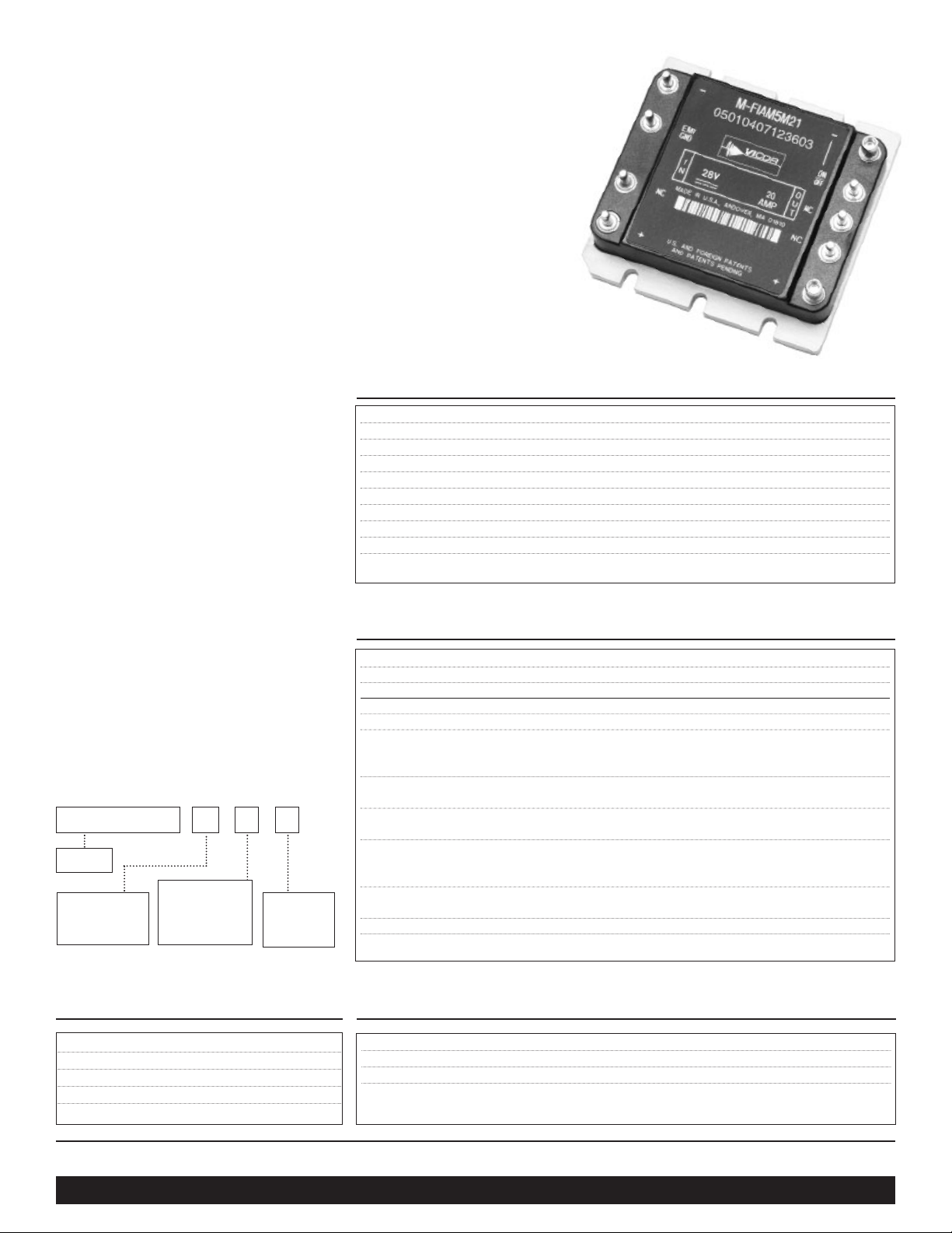
M-FIAM5
Military 28Vin Filter
Input Attenuator Module
45
Shown actual size:
2.28 x 2.2 x 0.5 in
57,9 x 55,9 x 12,7 mm
Specifications
(typical at TBP = 25ºC, nominal line, 75% load, unless otherwise specified)
Absolute Maximum Rating
M-FIAM5 M 2 1
Product
Baseplate
1 = Slotted
2 = Threaded
3 = Thru-hole
Product Grade(°C)
H = –40 to +100
M = –55 to +100
Temp Environment MTBF Unit
25°C Ground Benign:G.B. 3,334,295 Hrs
50°C Naval Sheltered:N.S. 786,893 Hrs
65°C Airborne Inhabited Cargo:A.I.C. 650,187 Hrs
MTBF per MIL-HDBK-217F
Pin Style
1 = Short
2 = Long
*S=Short ModuMate
*N=Long ModuMate
1
MIL-STD-704E Compliance requires an external circuit. See addendum A
Page 2
Vicor Corp. Tel: 800-735-6200, 978-470-2900 Fax: 978-475-6715 MFIAM5 Rev. 1.7 Page 2 of 5
Set your site on VICOR at www.vicorpower.com
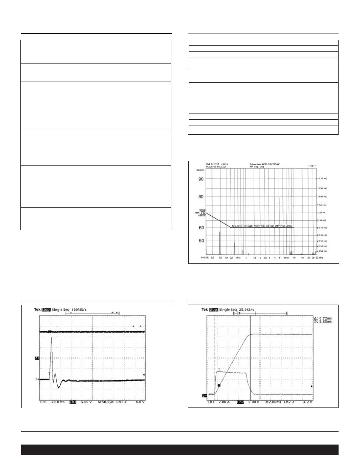
Transient Immunity
Inrush Limiting
Figure 2 – Transient Immunity: M-FIAM5 output response to
an input transient.
Figure 3– Inrush Limiting: Inrush current with
1000
µF
external capacitance.
Environmental Qualification
Altitude
MIL-STD-810C, Method 500.2, Procedure I & II, 40,000 ft. and
70,000 ft. Operational.
Explosive Atmosphere
MIL-STD-810F, Method 511.4, Procedure I, Operational.
Vibration
MIL-STD-810F, Method 514.5, Procedure I, Category 14, Sine
and Random vibration per Table 514.5C for Helicopter AH-6J
Main Rotor with overall level of 5.6 grams for 4 hours per axis.
MIL-STD-810F, Method 514.5C, General Minimum Integrity
Curve per Figure 514.5C-17 with overall level of 7.7 grams
for 1 hour per axis.
Shock
MIL-STD-810-F, Method 516.5, Procedure I, Functional Shock,40 G's.
MIL-S-901D, Lightweight Hammer Shock, 3 impacts/axis, 1,3,5 ft.
MIL-STD-202F, Method 213B, 60 G's, 9ms half sine.
MIL-STD-202F, Method 213B, 75 G's, 11ms Saw Tooth Shock.
Acceleration
MIL-STD-810F, Method 513.5, Procedure II, table 513.5-II,
Operational, 2-7 G's, 6 directions.
Humidity
MIL-STD-810F, Method 507.4, Procedure I, Cycle I, 240 hrs, 95% RH.
Solder Test
MIL-STD-202F, Method 208, 8 hour aging.
H Grade M Grade
Operating Temp. -40°C to +100°C -55°C to +100°C
Storage Temp. -55°C to +125°C -65°C to +125°C
Temp. Cycling:*
12 cycles 12 cycles
-65°C to +100°C -65°C to +100°C
Ambient Test
@ 25°C
Yes Yes
Power Cycling 12 hours, 24 hours,
Burn-In: 28 cycles 56 cycles
Functional and
Parametric
-40°C and -55°C and
ATE Tests:
+100°C +100°C
Hi-Pot Test Yes Yes
Visual Inspection: Yes Yes
Test Data vicorpower.com vicorpower.com
Environmental Stress Screening
Conducted Noise
Figure 1– M-FIAM5 and Model V24A12M400A
DC-DC converter operating at 28Vdc, 400W.
*Temperature cycled with power off, 17°C per minute rate of change.
Page 3

Vicor Corp. Tel: 800-735-6200, 978-470-2900 Fax: 978-475-6715 MFIAM5 Rev. 1.7 Page 3 of 5
Set your site on VICOR at www.vicorpower.com
(2X)
0.01
0.35
8,8
0.20**
5,1
0.12*
3,1
DIA,(7X)
0.150
3,81
(REF)
DIA,(2X)
0.080
2,03
431
98276 5
0.23
5,8
0.400
10,16
1.400
35,56
1.000
25,40
0.700
17,78
2.20
55,9
1.74
44,2
FULL R (6X)
(6X)
(REF.)
0.10
2,5
1.30
33,0
2.28
57,9
2.20
55,9
0.130
3,30
0.49
12,4
0.65
16,5
0.06
1,5
R(3X)
X 45˚
CHAMFER
Use a 4-40 Screw (6X)
Tor que to:
5 in-lbs
.57 N-m
0.54
13,7
0.43
10,9
Pin Style 2&N
(Long Pin)
0.62
15,7
Pin Style 1&S
(Short Pin)
(9X)
(9X)
Slotted (Style 1)
or
Threaded (Style 2)
4-40 UNC-2B (6X)
or
Thru Hole (Style 3)
#30 Drill Thru (6X)
(0.1285)
(ALL MARKINGS
THIS SURFACE)
ALUMINUM
BASEPLATE
0.50 ±0.02
12,7 ±0,5
* Style 1 baseplate only
** Style 2 & 3 baseplates
*** Reserved for Vicor accessories
Not for mounting
style 2 & 3
baseplates only
(4X)***
0.300 ±0.015
7,62 ±0,38
0.300 ±0.015
7,62 ±0,38
1.900
48,26
2.000
50,80
0.10
2,5
PCB Mounting Specifications
Transient and Surge Protection
Module Pins
No. Function Label
1 +In +
2
No
NC
Connection
3 Ground EMI/GND
4–In –
5–Out –
6 ON/OFF ON/OFF
7
No
NC
Connection
8
No
NC
Connection
9 +Out +
Mechanical Diagram
C1
Capacitance (C1)
330µF(min),1000µF(max)
Recommended Fuse:
20A Max., F03A Type
Note: The M-FIAM5 is shown in the on state. To disable,
open the connection between ON/OFF and –Out.
–IN
MOV P/N
20461-068
+IN
–
EMI
GND
M-FIAM5
NC
++
OFF
–
ON
NC
NC
–IN
2nd Generation
PR
PC
DC-DC Converters
+IN
24Vdc Input
–OUT
+OUT
–S
SC
+S
0.062 ±0.010
1,57 ±0,25
12 34
0.700*
17,78
1.000*
25,40
1.790
45,47
1.400*
35,56
56789
PLATED
THRU HOLE
DIA
* DENOTES
TOL =
1.584*
40,23
±0.003
±0,08
0.06
R (4X)
1,5
1.900*
1.900*
48.26
48,26
0.400*
10,16
PCB THICKNESS
0.195
4,95
(7X)
(2X)
0.158
4,01
INBOARD
SOLDER
MOUNT
PIN STYLE 1&S
0.094 ±0.003
2,39 ±0,08
0.164 ±0.003
4,16 ±0,08
0.43
10,9
PIN STYLE 2&N
ONBOARD
SOLDER
MOUNT
0.094 ±0.003
2,39 ±0,08
0.164 ±0.003
4,16 ±0,08
0.53
13,5
ALL MARKINGS
THIS SURFACE
ALUMINUM
BASEPLATE
PINS STYLES
STYLE 1 & 2: TIN/LEAD
HOT SOLDER DIPPED
STYLE S & N: GOLD PLATED COPPER
Page 4

Set your site on VICOR at www.vicorpower.com
Vicor Corp. Tel: 800-735-6200, 978-470-2900 Fax: 978-475-6715 MFIAM5 Rev. 1.7 Page 4 of 5
MIL-STD-704E Transient /Overvoltage Protection
The standard (COTS) 24V input 2nd Generation Converter Modules may be used in Military 28 volt applications. The
M-FIAM5 provides compliance to MIL-STD-461E conducted emissions and susceptibility standards. Additional circuitry,
as illustrated in the accompanying schematic (see Fig. 1), provides compliance to the MIL-STD-704E transient
overvoltage specification. The 24V input modules employ undervoltage and overvoltage protection. These converters,
shut down if the input falls below 18V or rises to 36V or above.18V is consistent with the MIL-STD-704E specification,
but the standard also requires uninterrupted performance in the event of an input voltage transient to 50V for a period
of 12.5 millisec. The above referenced circuit clamps the input voltage, in the event that it exceeds 32V, as illustrated in
figure 2. This performance prevents the converter from shutting down, thus meeting the transient overvoltage
specification of MIL- STD-704E.
Figure 1– Transient / Overvoltage protection circuit.
Figure 2– Overvoltage clamping
Addendum A
+28V
Transient Surpressor Circuit
Input
R1
2.0k
D1
15v, 1N5245B
+28v
rtn
R2
2.0k
C1
4.7uf, 63v
R3
64.9k
R5
10K
R4
64.9k
Vicor FIAM & Mods
Vc
C3
Cbulk
880 Uf d
U1A
LM258N
8
3
615001
+
1
2
–
4
R6
10K
1.0k
R7
R8
24.3k
2
3
U2
LM4040CIZ-5.0
U1B
8
LM258N
5
+
7
6
–
R9
4
14.0k
C2
.1ufd
R10
1.0K
1
Vout
2
4
Q1
IRFP3710
ND PN
3
C1 4.7uF, 63V
C2 0.1uF
C3 880uF, 100V
D1 1N5245B
Q1 IRFP3710ND
R1 2.0K
R2 2.0K
R3 64.5K
R4 64.5K
R5 10K
R6 10K
R7 1K
R8 24.3K
R9 14K
R10 1K
U1 LM258N
U2 LM4040CIZ-5.0
Volts
50
28
27
32
12.5 Millisec Max
Vin
Vout
Page 5

Vicor Corp. Tel: 800-735-6200, 978-470-2900 Fax: 978-475-6715 MFIAM5 Rev. 1.7 04/03/10M
Vicor’s comprehensive line of power solutions includes modular, high
density DC-DC converters and accessory components, configurable power
supplies, and custom power systems.
Information furnished by Vicor is believed to be accurate and reliable. However, no responsibility is
assumed by Vicor for its use. No license is granted by implication or otherwise under any patent or patent
rights of Vicor. Vicor components are not designed to be used in applications, such as life support systems,
wherein a failure or malfunction could result in injury or death. All sales are subject to Vicor’s Terms and
Conditions of Sale, which are available upon request.
Specifications are subject to change without notice.
Vicor Corporation
25 Frontage Road
Andover, MA, USA 01810
Tel: 800-735-6200
978-470-2900
Fax: 978-475-6715
Email
Vicor Express: vicorexp@vicr.com
Technical Support: apps@vicr.com
Component Solutions
for Your Power System
 Loading...