

Page 1
28
Applications
• Ethernet 10 or 100Mbps
• Token Ring
• Fibre Channel 266Mbps
• FDDI
• ATM-SDH/SONET 155Mbps
• Intra-Office Telecom
• WDM Applications
Features
• Full Duplex Communication
Over One Fiber
• Dual Wavelengths
820/1300nm
• Very Small Size
• Very Low Internal Crosstalk
• Packaged in Industry-
Standard ST® Receptacle
• Designed for 62.5/125µm
Fiber
Description
Used in combination with the
MF699, the MF-799 Duplex
Device is designed for WDM
(Wavelength Division Multiplex),
Datacom, Video Links, or IntraOffice Telecom Applications. It
emits optical power at 820nm
and detects incoming optical
power at 1320nm, allowing full
Duplex Communication over
one single fiber.
The MF799 uses dichroic
(wavelength-selective)
beamsplitters for maximum
power budget and minimum
crosstalk. Minimum internal
crosstalk is achieved by the
use of wavelength-selective
Detectors. The long wavelength
path meets requirements for
FDDI (ANSI X3T9.5 and ATM
155Mbps.
The MF799 is designed for
multi-mode fiber and optimized
for 62.5/125µm fiber.
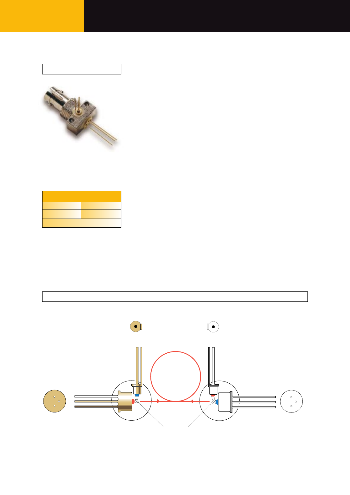
ST Assembly
MF799 ST
13329.11 1997-04-01
MF799 Datacom, Video Link, Intra-Office Telecom, WDM Duplex Device
Ordering Information
PART # RECEPTACLE
MF799 ST
-40°C to +85°C
MF799 Functional Diagram
ANODE
CATHODE
BOTTOM VIEW
CASE
MF799
LED
820nm
BOTTOM VIEW
CATHODE
PIN
1320nm
FIBER
DICHROIC
BEAMSPLITTER
BOTTOM VIEW
PIN
820nm
ANODEANODE
MF699
LED
1320nm
ANODE
CASE
CATHODE
BOTTOM VIEW
Page 2
29
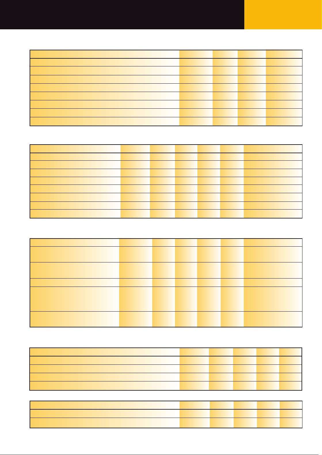
LED Optical & Electrical Characteristics (Case Temperature -25 to +70˚C)
Units
dBm
ns
MHz
nm
nm
V
µA
pF
Test Conditions
I
Peak
=60mA (Note 1, 2)
IF=60mA (Note 2)
IF=60mA (Note 2)
IF=60mA
IF=60mA
IF=60mA
VR=1V
VR=0V, f=1MHz
Max.
2
840
60
2.1
20
Min.
-19
800
Typ.
1.5
250
820
50
20
Symbol
P
fiber
trt
f
f
c
λ
p
∆λ
V
F
I
R
C
Parameter
Fiber-Coupled-Power (Fig 1)
Rise & Fall Time (10-90% no bias)
Bandwidth (3dBel)
Peak Wavelength
Spectral Width (FWHM)
Forward Voltage (Fig 3)
Reverse Current
Capacitance
Note 1: Average power at 10MHz/50% duty cycle. Measured at the exit of 100m of fiber. Note 2: 62.5/125µm graded index fiber (NA=0.275).
Absolute Maximum Ratings*
Units
°C
°C
mW
mA
mA
V
V
°C
Max.
+85
+85
250
110
180
1.5
20
260
Min.
-40
-40
Symbol
T
stg
T
op
P
tot
I
F
I
FRM
V
RL
V
RP
T
sld
Parameter
Storage Temperature
Operating Temperature (Fig 2)
LED Power Dissipation (Fig 2)
LED Continuous Forward Current (f≤10kHz)
LED Peak Forward Current (Duty cycle ≤50%, f≥1MHz)
LED Reverse Voltage
PIN Reverse Voltage
Solder Temperature (Note 1)
*Exceeding these values may cause permanent damage. Functional operation under these conditions is not implied. Note 1: 2mm from the case for 10s.
PIN Optical & Electrical Characteristics (Case Temperature -25 to +70˚C)
Units
A/W
MHz
pF
nA
nA
Test Conditions
VR=5V λ=1320nm
(note 1)
VR=5V RL=50Ω
(note 1)
VR=5V f=1MHz
T
Case
=25˚C
T
Case
=70˚C
VR=5V I
LED
=0mA
VR=5V I
LED
=60mA
(note 2)
Max.
5
100
Min.
0.5
500
Typ.
1.6
75
Symbol
R
f
c
C
I
d
I
Cr
Parameter
Responsivity (Fig 4)
Bandwidth
Capacitance (Fig 5)
Dark Current
Crosstalk Current
Note 1: 62.5/125µm graded index fiber (NA=0.275) Note 2: Internal crosstalk with ceramic ferrule inserted but no power from the fiber. Total Current = Dark
Current + Crosstalk Current.
LED Thermal Characteristics
Units
˚C/W
˚C/W
%/˚C
nm/˚C
Max.
200
300
Min. Typ.
-0.6
0.3
Symbol
R
thjc
R
thjb
dP/dT
j
dλ/dT
j
PIN Thermal Characteristics
Units
%/˚C
%/˚C
Max.Min. Typ.
5
-0.6
Symbol
dId/dT
j
dICr/dT
j
Parameter
Temperature Coefficient - Dark Current
Temperature Coefficient - Crosstalk Current
Datacom, Video Link, Intra-Office Telecom, WDM Duplex De vice MF799
Parameter
Thermal Resistance - Infinite Heat Sink
Thermal Resistance - On PC Board
Temperature Coefficient - Optical Power
Temperature Coefficient - Wavelength
Page 3

30
Figure 5
Figure 1
Figure 2
Figure 3
Figure 4
mA
200
100
0
0
1 2
3
V
0
20
40
60
80
100
%
0
40 80
120
160
200
mA
RELATIVE FIBER-COUPLED POWER
50% DUTY CYCLE
DC
HEAT SINKED
800
1000
1800
nm
0
100
%
1300
1500
900 1100
1200
1400 1600
1700
50
0
2.0
4.0
pF
0
5
10
V
REVERSE VOLTAGE
CAPACITANCE
mW
300
200
100
0
0 50 100
150 ˚C
ON PC BOARD
INFINITE
HEAT SINK
FORWARD CURRENT
MAX. ELECTRICAL POWER DISSIPATION
OPERATING TEMPERATURE
FORWARD CURRENT
FORWARD VOLTAGE
RELATIVE RESPONSIVITY
WAVELENGTH
MF799 Datacom, Video Link, Intra-Office Telecom, WDM Duplex Device
Page 4

31
MF799 Mechanical Data
MF799 Packaging Hardware
Note: The LED chip is isolated from the case. All dimensions in mm.
Datacom, Video Link, Intra-Office Telecom, WDM Duplex De vice MF799
2-56 UNC - 2B
LED
PIN DIODE
max. 1
1.44. 1 r0.3
3/8" - 32 UNEF
2.5
5.4
12.7
9.5
MARKING/ SLOT SIDE
9.6
21
min. 12
3.9
6.8
3/8 - 32 UNEF
2B THREAD
20.1
Ø2.502
+0.01
0
FIBER
END
Ø2.5
+0
-0.004
MATING FERRULE
(not included)
0.006
7.89 66 0.03
9.53
HEX-NUT
WASHER
10.41
12.70
1.65
14.27
0.46
Page 5

http://www.mitelsemi.com
World Headquarters - Canada
Tel: +1 (613) 592 2122
Fax: +1 (613) 592 6909
North America Asia/Pacific Europe, Middle East,
Tel: +1 (770) 486 0194 Tel: +65 333 6193 and Africa (EMEA)
Fax: +1 (770) 631 8213 Fax: +65 333 6192 Tel: +44 (0) 1793 518528
Fax: +44 (0) 1793 518581
Information relating to products and services furnished herein by Mitel Corporation or its subsidiaries (collectively “Mitel”) is believed to be reliable. However, Mitel assumes no
liability for errors that may appear in this publication, or for liability otherwise arising from the application or use of any such information, product or service or for any infringement of
patents or other intellectual property rights owned by third parties which may result from such application or use. Neither the supply of such information or purchase of product or
service conveys any license, either express or implied, under patents or other intellectual property rights owned by Mitel or licensed from third parties by Mitel, whatsoever.
Purchasers of products are also hereby notified that the use of product in certain ways or in combination with Mitel, or non-Mitel furnished goods or services may infringe patents or
other intellectual property rights owned by Mitel.
This publication is issued to provide information only and (unless agreed by Mitel in writing) may not be used, applied or reproduced for any purpose nor form part of any order or
contract nor to be regarded as a representation relating to the products or services concerned. The products, their specifications, services and other information appearing in this
publication are subject to change by Mitel without notice. No warranty or guarantee express or implied is made regarding the capability, performance or suitability of any product or
service. Information concerning possible methods of use is provided as a guide only and does not constitute any guarantee that such methods of use will be satisfactory in a specific
piece of equipment. It is the user’s responsibility to fully determine the performance and suitability of any equipment using such information and to ensure that any publication or
data used is up to date and has not been superseded. Manufacturing does not necessarily include testing of all functions or parameters. These products are not suitable for use in
any medical products whose failure to perform may result in significant injury or death to the user. All products and materials are sold and services provided subject to Mitel’s
conditions of sale which are available on request.
M Mitel (design) and ST-BUS are registered trademarks of MITEL Corporation
Mitel Semiconductor is an ISO 9001 Registered Company
Copyright 1999 MITEL Corporation
All Rights Reserved
Printed in CANADA
TECHNICAL DOCUMENTATION - NOT FOR RESALE
 Loading...