

Page 1
Product Specification
MF601HK
Data sheet subject to change without notice RDPS-MF034(R0)01/03/2002
SHEET 1 OF 5
File No RDPS-MF034
Revision R0
System Application Asymmetric Digital Subscriber Line
Product Type Micro Filter for ADSL CPE SIDE
Product Name MF601HK
Date Jan . 03th, 2002
Bert Lin - Design Engineer, R&D_1Issued By
Roger Wu – Manager, R&D_1Approved By
Issued Date
YCL Electronics Co., Ltd.
No.95, Feng Jen Road. Feng Shan City, Kaohsiung, Taiwan, R.O.C.
This controlled document is the property of YCL Electronics Co., Ltd. Any duplication
reproduction or transmission by unauthorized parties without the prior written
permission of YCL Electronics Co., Ltd. is prohibited.
Page 2
Product Specification
MF601HK
Data sheet subject to change without notice RDPS-MF034(R0)01/03/2002
SHEET 2 OF 5
General Description
The in-Line Micro filter has been specifically
designed to implement the functionality of low
pass filter in G.Lite system.
G.Lite technology is similar to full rate ADSL in
using DMT technology but operates at a lower
data rate of up to 1.5Mbps downstream and
512Kbps upstream ,depending on line conditions
and lengths.
This in-line filter will block the high frequency
energy from reaching the POTS devices and
provide isolation from impedance effects of the
POTS device on G.Lite.
In addition , this filter will also attenuate any
wideband impulse noise generated by the POTS
device due to the interruption of loop current(e.g.
pulse dialing or on hook / off hook transition)
Features
♦Consist exclusively of passive element.
♦Handle all POTS loop currents from
0mA to 100mA.
♦Designed for implementation of ADSL
CPE application.
♦Provides excellent isolation between
DSL and POTS.
♦Designed to meet G.Lite requirement.
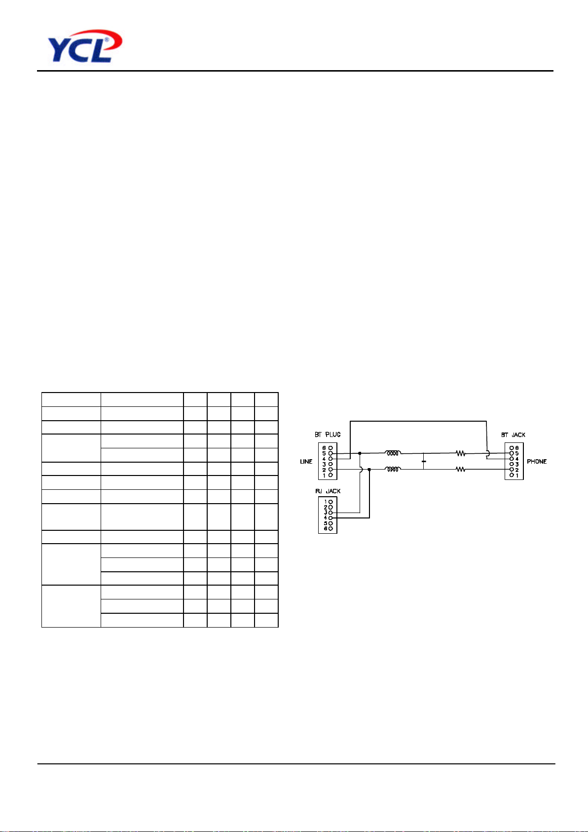
Specifications Schematic
Parameter Condition Min. Typ. Max Unit
Filter order 2
Impedance @300-4KHz 600Ω
@25KHz~50KHz -22 dB
Attenuation
@50KHz~1100KHz -40 dB
DCR Each line 50 Ω
Group delay @0.6-3.2KHz 100 µs
DC Current 100 mA
Longitudinal
balance
@0.2-3KHz -58 dB
Insertion Loss @200Hz~4KHz -1 dB
@300Hz~2000Hz -18 dB
@2200Hz~3000Hz -14 dB
Return loss
into line side
@3400Hz~3900Hz -12 dB
@300Hz~2000Hz -18 dB
@2200Hz~3000Hz -14 dB
Return loss
into Phone
side
@3400Hz~3900Hz -12 dB
Page 3
Product Specification
MF601HK
Data sheet subject to change without notice RDPS-MF034(R0)01/03/2002
SHEET 3 OF 5
Introduction
ADSL Lite is proposed as a lower speed version
of ADSL that will eliminate the need for telecom
to install and maintain a premises based POTS
splitter.
Recent field trials of DSL Lite equipment jointly
carried out by a group of manufacturers and a
North America network operator has proved the
technology , achieving maximum data rate for
distance up to 15000 feet. It was found
necessary to include one or more low pass
filters in series with the POTS terminals in order
to reliably achieve maximum dada rates.
For POTS voice band service , the low pass
filter provide protection from ADSL signal which
may impact through non-liner or other effects
remote devices (handset , fax, voice band
modem etc)and central office operation.
For ADSL signal , it also provide protection from
the high frequency transient and impedance
effect that occur during POTS operation
( ringing transients , on-hook , off-hook transient
and so on).
DC characteristic
All requirement of this specification can be met
in the presence of all POTS loop currents from
0mA to 100mA.
This in line filter can pass POTS tip-to-ring dc
voltages of 0V to 105V and ringing signals of
40V to 150Vrms at any frequency from15.3Hz
to 68Hz with a dc component in the range from
0V to 105V.
The dc resistance from tip-to-ring at the line port
interface with the phone interface shorted, shall
be less than or equal to 100 ohms.
The DC resistance from tip-to-ground and
from ring-to-ground at the POTS interface
with the U-R interface open shall be greater
than or equal to 5 Megohms.
The ground point shall be local building or green
wire ground. As an objective , the dc resistance
should exceed 10MΩ.
ZHP-r Defined
To facilitate testing of the inline filterindependently of the actual modem or specific vendor ,
ZHP-r is defined to allow proper termination of
the XDSL port during voice band testing.
The ZHP-r is valid only for voice band
frequency.
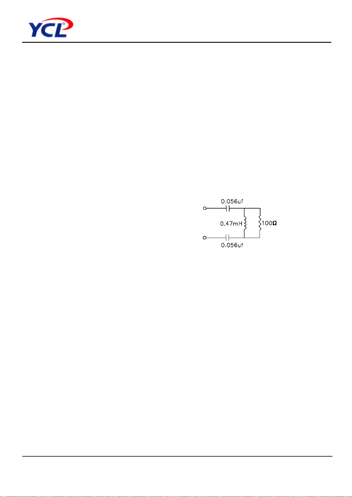
The combination of capacitors in the
ZHP-r is only representative. The input
shall be 27nF however derived. ZNP-r
equivalent circuit is shown in Figure 1.
Figure 1
Page 4
Product Specification
MF601HK
Data sheet subject to change without notice RDPS-MF034(R0)01/03/2002
SHEET 4 OF 5
POTS band added insertion loss Installation
In general , the insertion loss is defined as the
ratio , expressed in dB of the power delivered
to a load with the circuit in place and the
power delivered to a load without the circuit in
place.
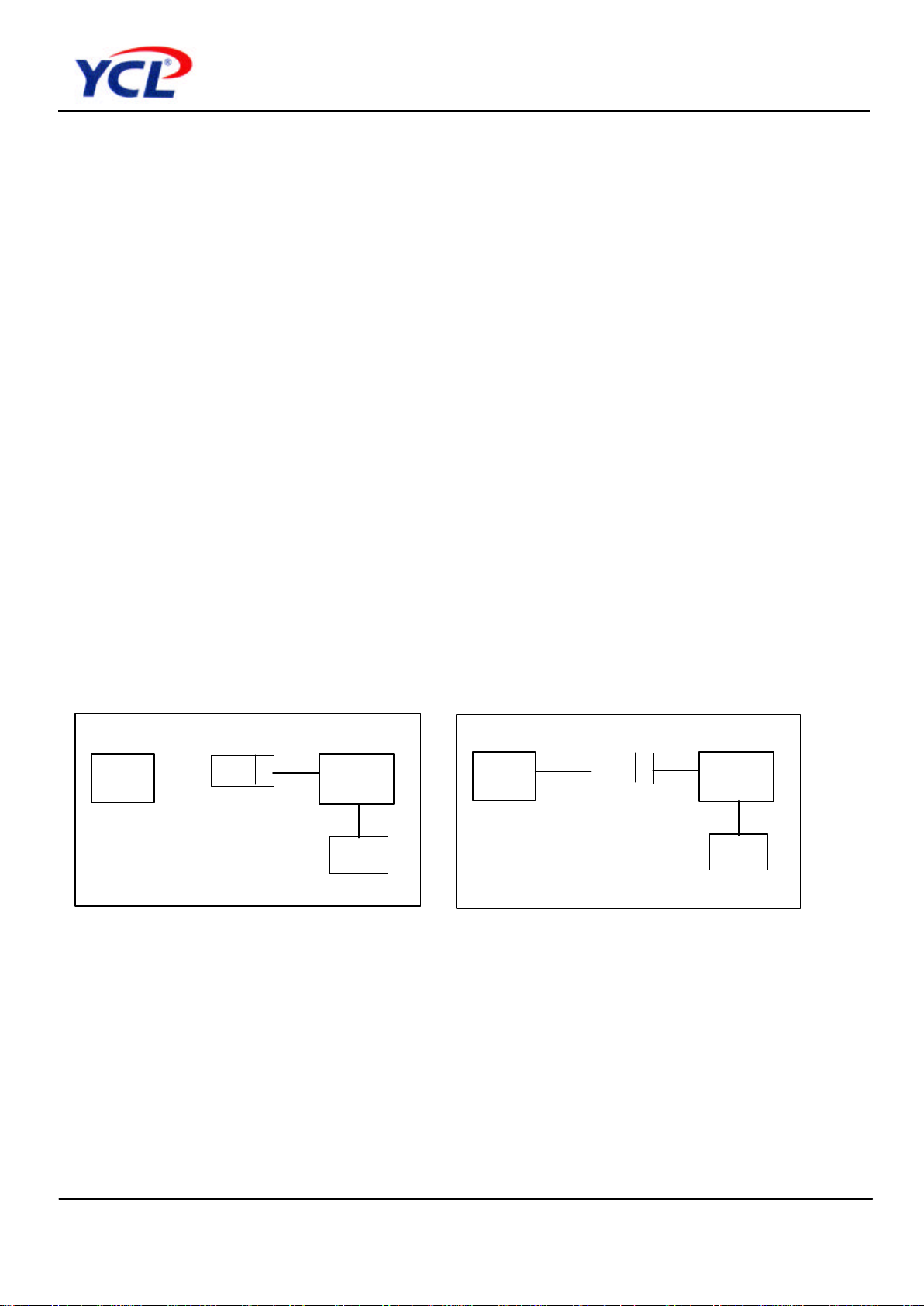
The added insertion loss shall be measured
using the test up in Figure 2. For measuring
POTS band insertion for single filter module
also a single filter with four added parallel load
filters
Return loss
Return loss is essentially defined as the
ratio ofthe power incident upon a given
transmission system to the power eflected
caused by impedance mismatch with
respect to reference impedance at the
interface between source and device.
Return loss shall be measured using the test
setup in Figure 3.
This unit have been equipped with two RJ11
Jack on both telephone interface and line
interface which are 6 position modular Jack ,
with cond-uctor 3 and 4 loaded.
Indicatory making( eg. Phone , line) have been
provided on the top side of this unit to assist in
position during installation.
Figure 2. POTS Band Insertion loss Test Setup
Figure 3. POTS Band Return loss Test setup
TEST
LPF
Line
Phone
600Ω
Remote POTS Splitter
600Ω
Return loss reference
TEST
LPF
Line
Phone
600Ω
Remote POTS Splitter
600Ω
Page 5
Product Specification
MF601HK
Data sheet subject to change without notice RDPS-MF034(R0)01/03/2002
SHEET 5 OF 5
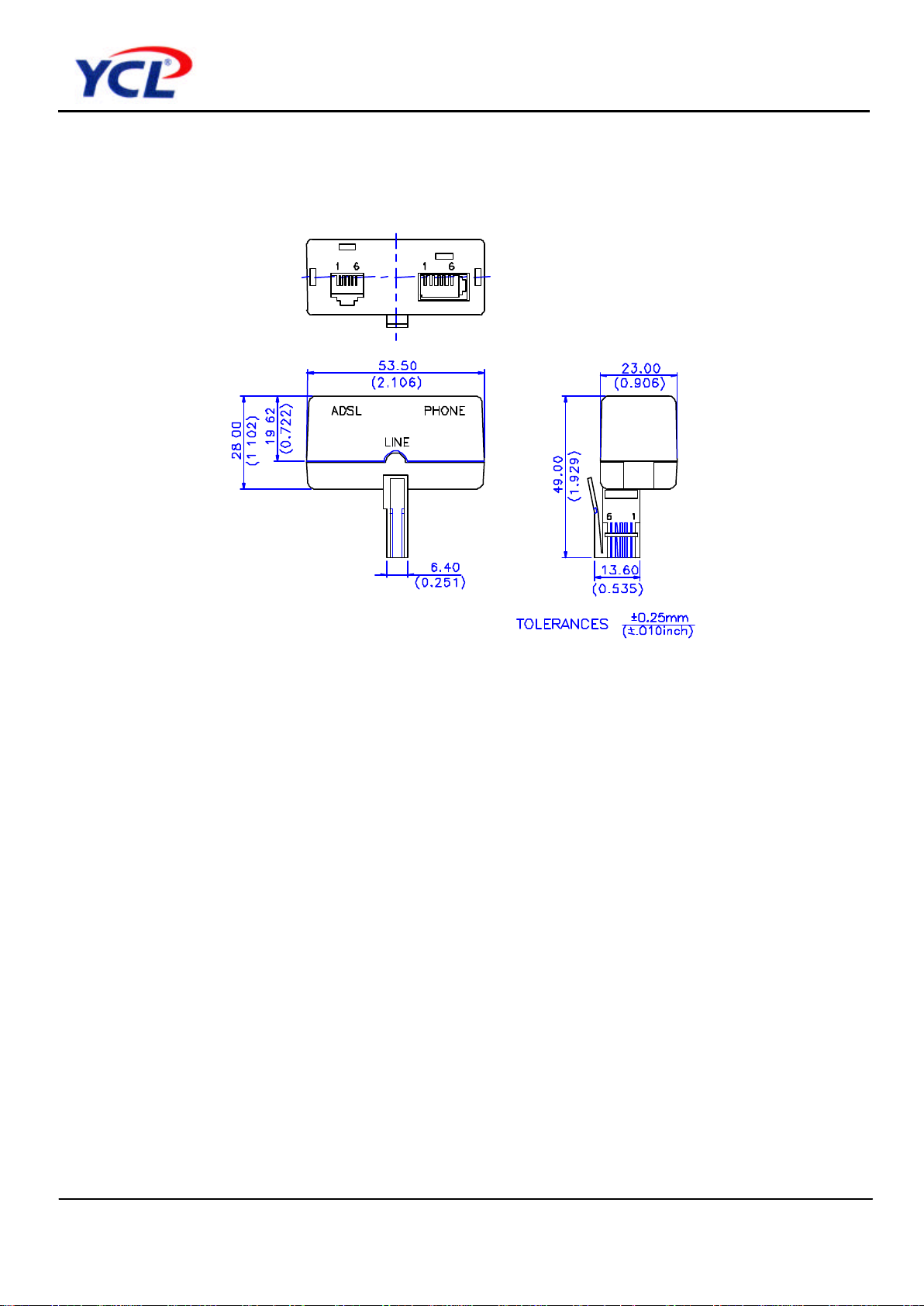
Dimension
 Loading...