

Page 1
14
Description
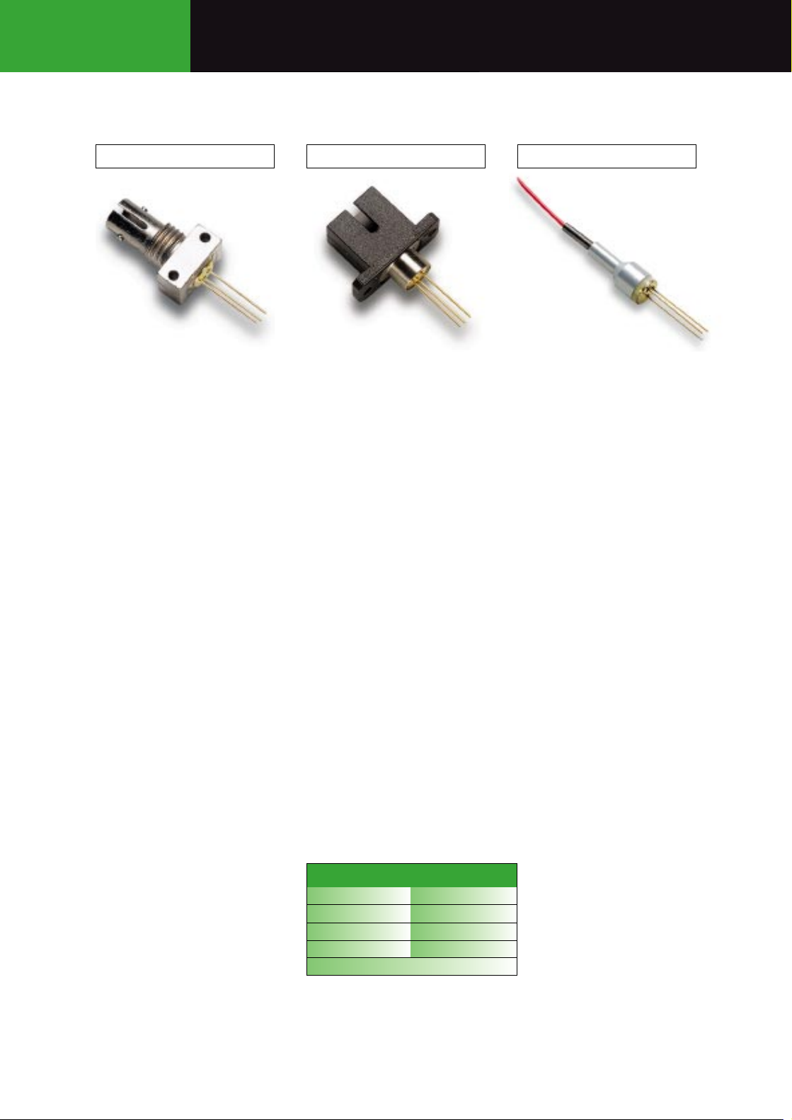
This family of PIN Photodiodes is designed for Datacom, Telecom
and General purpose applications. Their unique design combines high
bandwidth with high responsivity for single-mode as well as multimode
fibers up to 62.5µm core diameter. The MF432 PIN Photodiode is
available in ST, SC, or Pigtail package.
Specially-designed connectors and clips for PC board assembly
are included in deliveries of MF432 in SC and Pigtail configurations.
The MF431 LED is the recommended transmitter for these PIN
photodiodes.
ST Assembly
SC Assembly
Pigtail Assembly
MF432 ST
MF432 SC
MF432 Pigtail
ST Applications
• FDDI
• ESCON
• ATM-SDH/SONET 155,
622 and 2488Mbps
• FITL - Fiber In The Loop
• FTTH/FTTC - Fiber To
The Home/Curb
• Intra-Office
Telecommunications
• General Purpose
Pigtail Applications
•
ATM-SDH/SONET 155,
622 and 2488Mbps
•
FITL - Fiber In The Loop
•
FTTH/FTTC - Fiber To
The Home/Curb
SC Applications
• FDDI
• ESCON
• ATM-SDH/SONET 155,
622 and 2488Mbps
• FITL - Fiber In The Loop
• FTTH/FTTC - Fiber To
The Home/Curb
• Intra-Office
Telecommunications
• General Purpose
13325.11 1997-04-01
13326.11 1997-04-01
13327.11 1997-04-01
Features-All MF432 Devices
•
1300 and 1550nm PIN
Photodiode
•
2.5GHz Bandwidth
•
Designed for Single-Mode
and Multi-Mode Fiber
•
Aligned in ST®, SC
Receptacle or with a
Single-Mode Fiber Pigtail
•
Tested to Bellcore
TA-NWT-000983
•
High Return Loss in Pigtail
Configuration
MF432 Datacom, Telecom, General Purpose PIN Photodiodes
Ordering Information
PART # RECEPTACLE
MF431 ST ST
MF 432 SC SC
MF 432 Pigtail Pigtail
-40°C to +85°C
Page 2
15
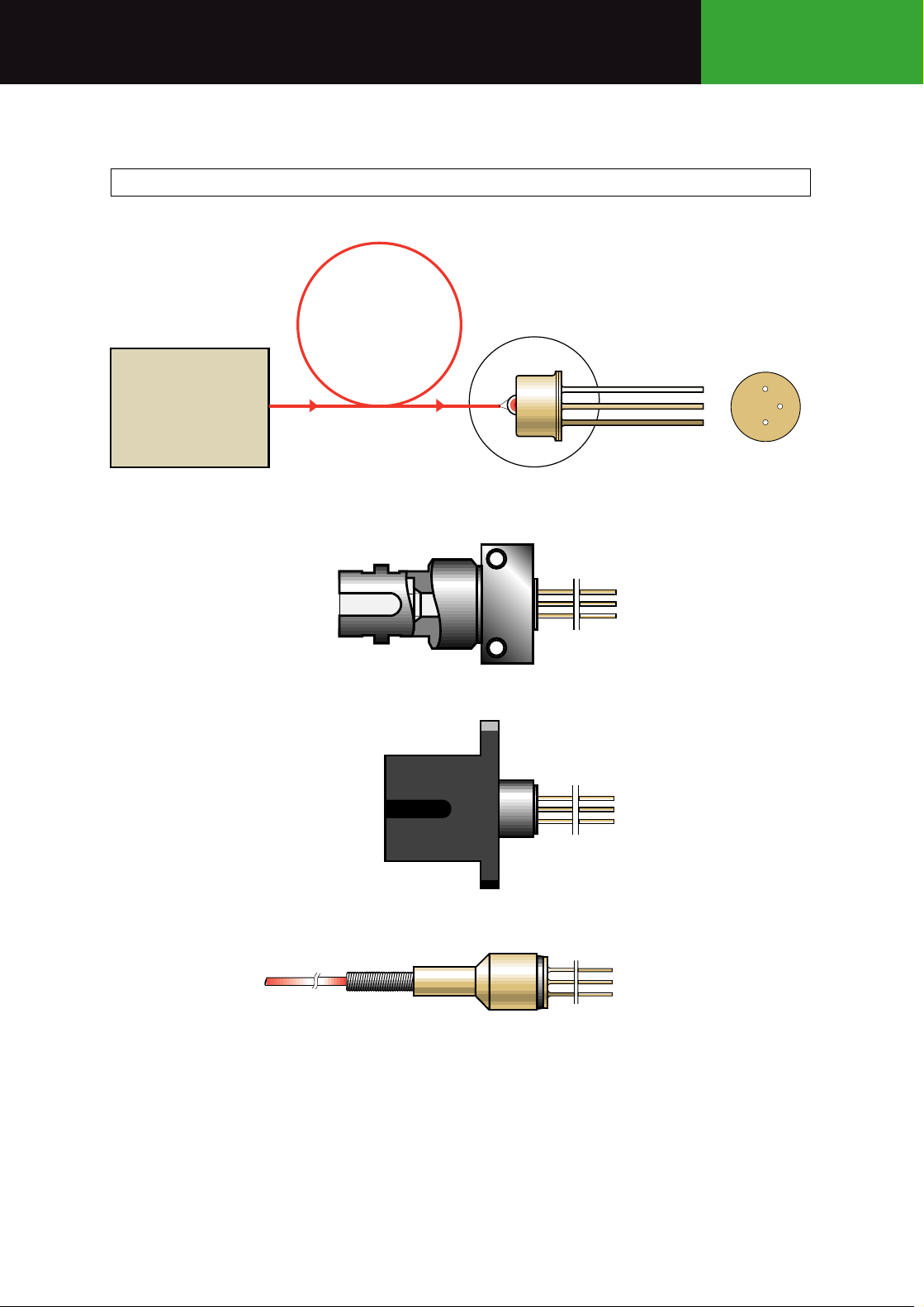
ST
SC
Pigtail
FIBER
EMITTER
BOTTOM VIEW
ANODE
CASE
CATHODE
MF432 PIN
Datacom, Telecom, General Purpose PIN Photodiodes MF432
MF432 Functional Diagram For ST, SC and Pigtail
Page 3
16
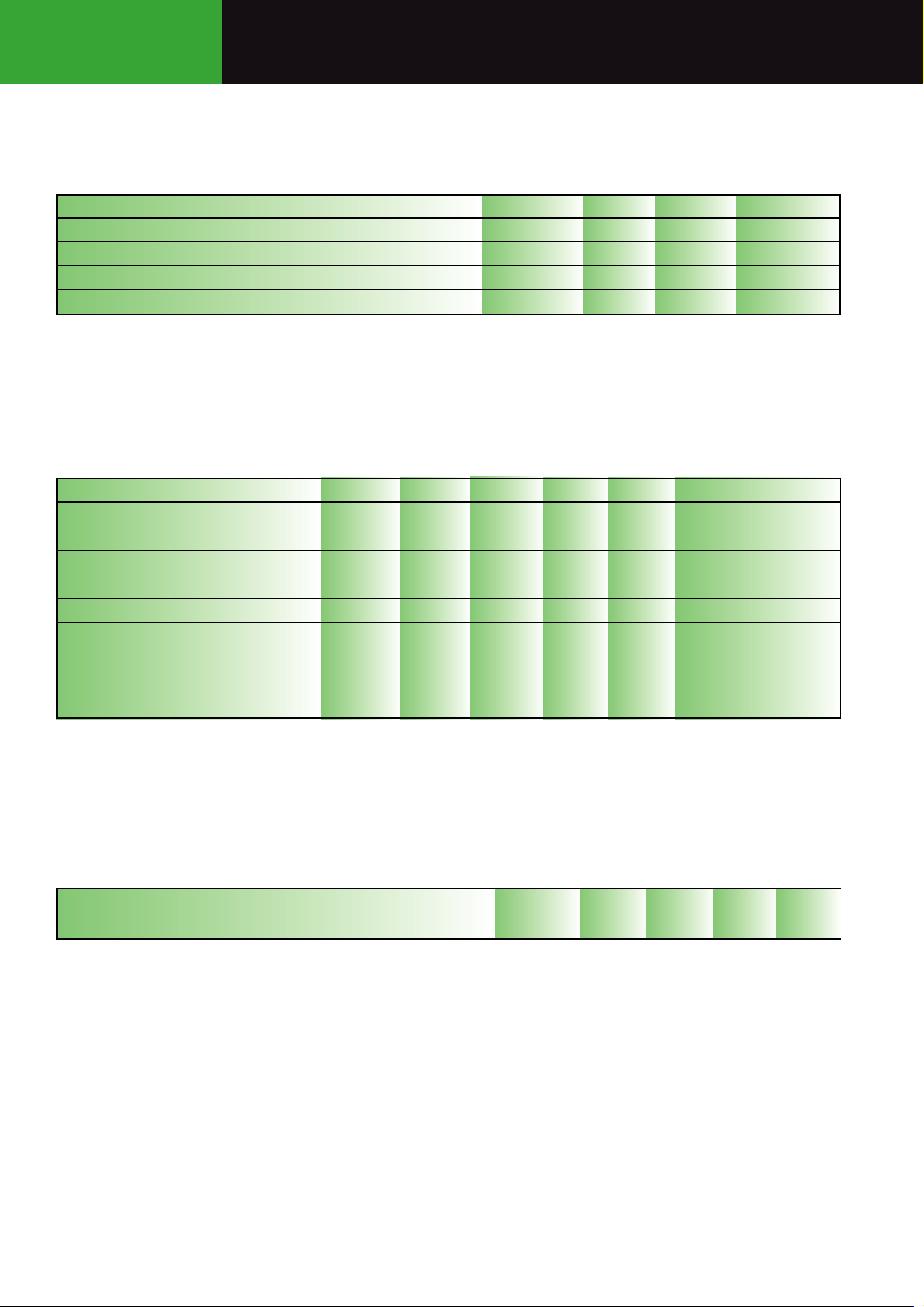
Optical & Electrical Characteristics (Case Temperature -25 to +70˚C)
Units
A/W
GHz
pF
nA
Test Conditions
λ=1300nm (Note 1)
λ=1550nm V
R
=5V
V
R
=5V RL=50Ω
(Note 1)
V
R
=5V f=1MHz
T
Case
=25˚C
T
Case
=70˚C
V
R
=5V
(Note 2)
Max.
1.2
3
50
Min.
0.7
0.8
2.5
40
Typ.
0.8
1.0
0.8
55
Symbol
R
f
c
C
I
d
RL
Parameter
Responsivity (Fig 1, 2, 3)
Bandwidth
Capacitance (Fig 4)
Dark Current
Return Loss
Note 1: Data for 10/125µm single-mode fiber (NA=0.11) to 62.5/125µm graded index fiber (NA=0.275).
Note 2: With 10/125µm single-mode fiber pigtail (NA:0.11).
Absolute Maximum Ratings*
Units
°C
°C
V
°C
Max.
+85
+85
20
260
Min.
-40
-40
Symbol
T
stg
T
op
V
R
T
sld
Parameter
Storage Temperature
Operating Temperature
Reverse Voltage
Soldering Temperature (Note 1)
Thermal Characteristics
*Exceeding these values may cause permanent damage. Functional operation under these conditions is not implied.
Note 1: 2mm from the case for 10s.
Units
%/˚C
Max.Min. Typ.
5
Symbol
dId/dT
j
Parameter
Temperature Coefficient - Dark Current
MF432 Datacom, Telecom, General Purpose PIN Photodiodes
Page 4

17
Figure 1
Figure 2
Figure 3
Figure 4
Datacom, Telecom, General Purpose PIN Photodiodes MF432
%
100
80
60
40
RELATIVE RESPONSIVITY
20
0
0.5
1.0 1.5
z - AXIAL DISPLACEMENT OF FIBER
%
100
r
Øc =
r = opt.
z
62.5 µm
%
100
80
60
40
RELATIVE RESPONSIVITY
20
2.0
2.5
3.0
mm
0
0
20 40
r
z = opt.
Øc =
62.5 µm
z
60
80
120
µm
r - RADIAL DISPLACEMENT OF FIBER
pF
2.0
50
RELATIVE RESPONSIVITY
0
1000
900 1100
800
WAVELENGTH
1200
1300
1400 1600
1500
1700
1800
1.0
CAPACITANCE
nm
0
0
5
REVERSE VOLTAGE
10
V
Page 5

18
Ø 6
0.4
2.5
5.4
min.12
MARKING
13
Ø6.00
Fiber length 1m
Ø2.3
Ø7.5
0.4
MARKING / SLOT SIDE
22
2.5
5.4
8.9
1.4 x 4
18
min. 12
12
2.5
7.95
0.006
FIBER
END
Ø2.5
+0
-0.004
RECOMMENDED FERRULE
(not included)
13
18
12.7
MARKING SIDE
SLOT SIDE
9.5
0.4
7.89
2-56 UNC - 2B
max.0.5
min.12 20.1
3.9
5.4
7.6
3/8"-32 UNEF
0.006
FIBER
END
Ø2.5
Ø2.502
+0.01
0
+0
-0.004
RECOMMENDED
FERRULE
(not included)
5.4
2.5
Note: The PIN chip is isolated from the case. All dimensions in mm.
MF432 Datacom, Telecom, General Purpose PIN Photodiodes
MF432 ST Mechanical Data
MF432 SC Mechanical Data
MF432 Pigtail Mechanical Data
Page 6

19
A typical Fiber Optic Receiver Circuit interfacing the PIN Photodiode
to a Philips NE52121 transimpedance amplifier (140MHz) and to
the Philips NE5211 FDDI Fiber Optic Postamplifier. This design is
capable of operating at 125Mbps with single +5 or -5.2V supply
with differential output impedance of 100k.
Typical Receiver Circuit
MF432 SC Clip MF432 Pigtail ClipST Packaging Hardware
SC Connector
on MF432 Pigtail
Datacom, Telecom, General Purpose PIN Photodiodes MF432
V
CC
47µF
GND
.01µF
220 Ω
10µH
10µF
10µH
10µF
.01µF
47kΩ
.01µF
LED
100pF
1
2
3
4
5
NE5214
6
7
8
9
10
(TTL)
V
OUT
20
100pF
19
18
0.1µF
17
16
15
14
13
12
11
5
6
7
8
5.1kΩ
NE5212A
2.2 - 3.2
10µH
4
3
2
1
10µF
.01µF
60 (max)
7.4 - 7.5
100Ω
MF432
PIN
OPTICAL INPUT
1µF
.01µF
2.0 - 2.2 9.0 - 9.1
R 1.00
3/8 - 32 UNEF
2B THREAD
9.53
12.70
HEX-NUT
10.41
WASHER
1.65
14.27
0.46
3.3000
5.6000
10,2500
80,000
0.5000
4.9500
0.5000
20.8200
10.25
10.3000
4.5000
5.0800
3.6450
0.50
4.95
0.50
0.85
10.70
10.30
4.50
5.08
3.65
Page 7

http://www.mitelsemi.com
World Headquarters - Canada
Tel: +1 (613) 592 2122
Fax: +1 (613) 592 6909
North America Asia/Pacific Europe, Middle East,
Tel: +1 (770) 486 0194 Tel: +65 333 6193 and Africa (EMEA)
Fax: +1 (770) 631 8213 Fax: +65 333 6192 Tel: +44 (0) 1793 518528
Fax: +44 (0) 1793 518581
Information relating to products and services furnished herein by Mitel Corporation or its subsidiaries (collectively “Mitel”) is believed to be reliable. However, Mitel assumes no
liability for errors that may appear in this publication, or for liability otherwise arising from the application or use of any such information, product or service or for any infringement of
patents or other intellectual property rights owned by third parties which may result from such application or use. Neither the supply of such information or purchase of product or
service conveys any license, either express or implied, under patents or other intellectual property rights owned by Mitel or licensed from third parties by Mitel, whatsoever.
Purchasers of products are also hereby notified that the use of product in certain ways or in combination with Mitel, or non-Mitel furnished goods or services may infringe patents or
other intellectual property rights owned by Mitel.
This publication is issued to provide information only and (unless agreed by Mitel in writing) may not be used, applied or reproduced for any purpose nor form part of any order or
contract nor to be regarded as a representation relating to the products or services concerned. The products, their specifications, services and other information appearing in this
publication are subject to change by Mitel without notice. No warranty or guarantee express or implied is made regarding the capability, performance or suitability of any product or
service. Information concerning possible methods of use is provided as a guide only and does not constitute any guarantee that such methods of use will be satisfactory in a specific
piece of equipment. It is the user’s responsibility to fully determine the performance and suitability of any equipment using such information and to ensure that any publication or
data used is up to date and has not been superseded. Manufacturing does not necessarily include testing of all functions or parameters. These products are not suitable for use in
any medical products whose failure to perform may result in significant injury or death to the user. All products and materials are sold and services provided subject to Mitel’s
conditions of sale which are available on request.
M Mitel (design) and ST-BUS are registered trademarks of MITEL Corporation
Mitel Semiconductor is an ISO 9001 Registered Company
Copyright 1999 MITEL Corporation
All Rights Reserved
Printed in CANADA
TECHNICAL DOCUMENTATION - NOT FOR RESALE
 Loading...