

Page 1
MITSUBISHI(Dig.Ana.INTERFACE)
PRELIMINALY
PRELIMINALY
Notices;This is not a final specification.
Some parametric limits are subject to change.
LITHIUM ION BATTERY CHARGER CONTROL IC
GENERAL DESCRIPTION
The M62253FP is a charge controller designed for charging
lithium ion batteries.
The IC has a current and voltage control circuit allowing the
constant current/voltage charging to lithium ion batteries.
A charger system for lithium ion batteries can be easily designed
by utilizing the IC`s following functions ;
• charge disabling function for an over discharged battery
• charge control function by detecting the battery temperature
FEATURES
• Constant current and voltage charging
• Charge disabling functions for an over discharged battery
and a high/low temperature battery
• Recharging function
• 2 LED driving circuits to Indicate charging conditions
• Delay circuit to prevent chattering
M62253FP
PIN CONFIGURATION(TOP VIEW)
TIN
C3
Vref
VDD
Vcc
LED1
LED2
1
2
3
4
5
6
M62253FP
7
Outline 14P2N-A
14
13
12
11
10
9
8
OUT
SENSE+
SENSE VSENSE
GND
C2
C1
APPLICATION
Lithium ion battery charger for digital equipment
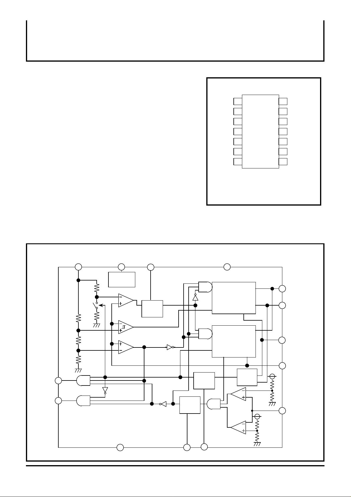
BLOCK DIAGRAM
Vref
3.0V
2.6V
VDD
Std.
VOLTAGE
4.1V to 3.9V
Incorrect
detect
prohibition
circuit
LED2
LED1
C1
Incorrect
detect
prohibition
circuit
Incorrect
detect
prohibition
circuit
Vcc
OE
Fixed current
control circuit
ISET
OE
Fixed voltage
control circuit
VSET
OUT
ISENSE+
ISENSE-
OUT
VSENSE
Current
detect
circuit
1.64V
VDD
R1
3.54V
R2
OUT
SENSE+
SENSE-
VSENSE
VDD
R1
R2
TIN
GND
( / 5 )
1
C2C3
Page 2

MITSUBISHI(Dig.Ana.INTERFACE)
PRELIMINALY
PRELIMINALY
Notices;This is not a final specification.
Some parametric limits are subject to change.
EXPLANATION OF TERMINALS
Pin
No.
Symbol
1
TIN
2 C3
3
4
Vref
VDD
Temperature detection (also using for battery connect detection)
Setting delay time of temperature detection (Tpd=50ms at 0.1µF)
Reference voltage of internal circuit.
5.0V reference voltage
M62253FP
LITHIUM ION BATTERY CHARGER CONTROL IC
Function
5 Vcc
6,7
8
9
10
11
12
13
14
LED1,2
C1
C2
GND
VSENSE
SENSE-
SENSE+
OUT
Power supply
LED connection (LED1 is on during charging, LED2 is on at charge
completion.)
Setting delay time of voltage detection (Tpd = 1.20sec at 2.2µF)
Setting delay time of current detection (Tpd = 1.30sec at 2.2µF)
Ground
Battery voltage detection
Charging current detection
Charging current detection
Output (open collector configuration)
( / 5 )
2
Page 3

MITSUBISHI(Dig.Ana.INTERFACE)
PRELIMINALY
PRELIMINALY
Notices;This is not a final specification.
Some parametric limits are subject to change.
ABSOLUTE MAXIMUM RATING
Symbol Parameter Test conditions Ratings Unit
Vcc Supply voltage 16
IOUT
VSENSE
TIN
Pd
Ktheata
Topr
Tstg
OUT pin output current
SENSE pin voltage
TIN pin voltage
Power dissipation
Thermal derating
Operating temperature
Storage temperature
ELECTRICAL CHARACTERISTICS
Block
Vcc
Icc
VDD
VDD
VTHchgon Charge start voltage
VTHqchgon Fast charge start voltage
VTHqchgoff
Vochg1
Vochg2 Output voltage set2
VTHrchgon
Voltage detect part
ISET1
ISET2
ITHchgoff
IINSENSE+
Current detect
part
IINSENSE- SENSE- pin input current
IoutLED1
IoutLED2 LED2 pin output current
LED
VOHLED1
VOHLED2
VTHINTH1
VTHINTL1
TIN
IinTIN TIN pin input current
VTHINTH2
VTHINTL2
OUT
ILOUT
C1
tdC1
tdBDET1
tdBDET2
C2
tdIDET C2= 2.2µF 1.65 s
tdILED C2= 2.2µF 3.2 s
tdchg
C3
tdC3 C3= 0.1µF ms
Supply voltage range
circuit current
VDD pin output voltage
Const current charge
stop voltage
Output voltage set1
Recharge start voltage
Charge current set voltage 1
Charge current set voltage 2
Charge complete
detect voltage
SENSE+ pin input current
LED1 pin output current
LED1 pin output "H"
voltage
LED2 pin output "H"
voltage
TIN pin up side threshold
voltage 1
TIN pin low side threshold
voltage 1
TIN pin up side threshold
voltage 2
TIN pin low side threshold
voltage 2
OUT pin saturation voltage
OUT pin leak current
Voltage detect delay time
Connect detect time 1
Connect detect time 2
Current detect delay time
LED switching delay time
Discharge time
Temperature
detect delay time
M62253FP
LITHIUM ION BATTERY CHARGER CONTROL IC
(Ta=25°C unless otherwise noted)
V
30
Vcc
Vcc
Ta = 25°C
Ta = 25°C
(Vcc=8.5V,Vref=4.10V,VSENSE=3.6V,Ta=25°C, unless otherwise noted)
450
4.5
-20 to +85
Limit
Test conditionParameterSymbol
TYP MAXMIN
6.0 15 V
LED OFF
5.004.75 5.25
2.6 V
3.0 V
4.09 V
4.10
2.55
3.9 V
25
250
60 85
60 85
10
8
10
8
0.410
2.050
Charge time
Charge complete time
Charge complete time
2.6V≤ battery voltage≤3.0V
3.0V≤ battery voltage≤4.1V
Const voltage charge time
Charge time
Charge time
Resistance ratio(R1/R2)
*in the block diagram
2.9 3.1
4.06
4.07
2.45
3.8
15
235
15
0.398 0.422
1.989 2.112
-1.0
Resistance ratio(R1/R2)
*in the block diagram
IOUT=20mAVOHOUT
VC=15V 1.0 µA
Recharge time@C1= 2.2µ F
4.1V output time C2= 2.2µ F
2.55V output timeC2= 2.2µ F
0.388 0.412
1.804 1.916
0.400
1.860
1.0 V
1.200.88
12088
1.300.95
2.51.8
C2= 2.2µF(After current detect)
36 64
9030
50
mA
V
V
mW
mW/°C
°C
°C-40 to +125
Unit
mA7
2.72.5
4.12
4.13
2.65
4.0
mV
35
35
mV
mV25
265
µA
µA
mA
12
mA
12
2.5
2.5
µA
2.0
1.52 s
1.63 s1.300.95
152 ms
ms
V
V
V
V
V
( / 5 )
3
Page 4

MITSUBISHI(Dig.Ana.INTERFACE)
PRELIMINALY
PRELIMINALY
Notices;This is not a final specification.
Some parametric limits are subject to change.
LITHIUM ION BATTERY CHARGER CONTROL IC
4. Timing chart (a case of application's constants)
(1) Timing of battery connecting detection
Battery connection point
4.1V
2.55V
Output voltage
Voltage
Detection
Current
Detection
50ms
0.55s
≈
55ms
Charge start
M62253FP
(2) Timing of temperature detection
45°C
42.5°C
≈
3°C
Battery temperature
Charge
50ms 50ms 50ms
ON
OFF
(3) Timing of charging
4.1V
3.9V
3.0V
2.6V
Battery voltage
Completion of battery
temperature detection
250mA
25mA
charge current
Charge
LED1 (red)
LED2 (green)
1.30S
0
ON
OFF
ON
OFF
Constant current charge
120mS
25mA 250mA
Constant
current charge
Constant voltage
charge
Vo=4.1V Vo=2.3V
Charge
completion
1.30S
1.20S
0.55S
Recharge
(Constant
current charge)
250mA
( / 5 )
4
Page 5

MITSUBISHI(Dig.Ana.INTERFACE)
PRELIMINALY
PRELIMINALY
Notices;This is not a final specification.
Some parametric limits are subject to change.
5. APPLICATION EXAMPLE
Vref
LED2
LED1
3.0V
2.6V
Std voltage
5.0V
4.1V to 3.9V
VDD
C1
Incorrect
detect
prohibition
circuit
M62253FP
LITHIUM ION BATTERY CHARGER CONTROL IC
2.2µF
Vcc
R1
R2
VDD
R1
R2
OUT
SENSE+
SENSE-
1Ω
VSENSE
To VDD pin
10KΩ
TIN
Battery
Incorrect
detect
prohibition
circuit
Incorrect
detect
prohibition
circuit
OE
current control
circuit
ISENSE+
ISENSE-
ISET
OE
voltage control
circuit
VSET
VSENSE
Current
detect circuit
OUT
OUT
1.64V
3.54V
GND
0.1µF
C2C3
2.2µF
( / 5 )
5
 Loading...