

Page 1
LM3911 Temperature Controller
General Description
The LM3911 is a highly accurate temperature measurement
and/or control system for use over a
b
25§Ctoa85§C temperature range. Fabricated on a single monolithic chip, it
includes a temperature sensor, a stable voltage reference
and an operational amplifier.
The output voltage of the LM3911 is directly proportional to
temperature in degrees Kelvin at 10 mV/
nal op amp with external resistors any temperature scale
K. Using the inter-
§
factor is easily obtained. By connecting the op amp as a
comparator, the output will switch as the temperature transverses the set-point making the device useful as an on-off
temperature controller.
An active shunt regulator is connected across the power
leads of the LM3911 to provide a stable 6.8V voltage reference for the sensing system. This allows the use of any
power supply voltage with suitable external resistors.
The input bias current is low and relatively constant with
temperature, ensuring high accuracy when high source impedance is used. Further, the output collector can be returned to a voltage higher than 6.8V allowing the LM3911 to
drive lamps and relays up to a 35V supply.
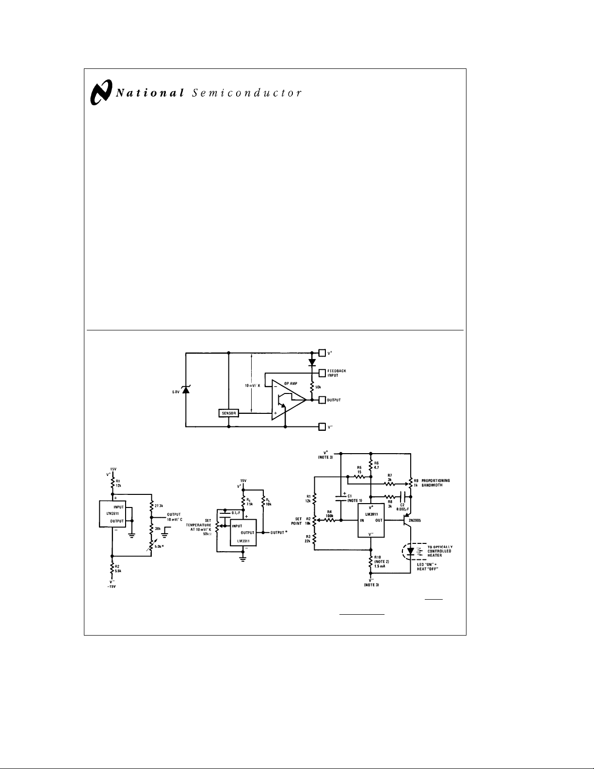
Block Diagram
The LM3911 uses the difference in emitter-base voltage of
transistors operating at different current densities as the basic temperature sensitive element. Since this output depends only on transistor matching the same reliability and
stability as present op amps can be expected.
The LM3911 is available in two package styles, a metal can
TO-46 and an 8-lead epoxy mini-DIP. In the epoxy package
all electrical connections are made on one side of the device allowing the other 4 leads to be used for attaching the
LM3911 to the temperature souce. The LM3911 is rated for
operation over a
Features
Y
Y
Y
Y
Y
Y
Y
b
25§Ctoa85§C temperature range.
Uncalibrated accuracyg10§C
Internal op amp with frequency compensation
Linear output of 10 mV/§K (10 mV/§C)
Can be calibrated in degrees Kelvin, Celsius or
Fahrenheit
Output can drive loads up to 35V
Internal stable voltage reference
Low cost
LM3911 Temperature Controller
June 1994
Typical Applications
Ground Referred
Proportioning Temperature
Controller
Centigrade Thermometer
Basic Temperature Controller
* Output goes negative on
temperature increase
a
e
b
R
(V
6.8V) kX
* Trims out initial zener tolerance.
Set output to read C
C
1995 National Semiconductor Corporation RRD-B30M115/Printed in U. S. A.
S
TL/H/5701
Note 1: C1 determines proportioning frequency f
Note 2: R10
Note 3: Either V
a
b
V
V
l
lal
e
0.0015A
b
or Vacan be ground.
b
7V
l
TL/H/5701– 1
&
2R4 C1
1
Page 2
Absolute Maximum Ratings
If Military/Aerospace specified devices are required,
please contact the National Semiconductor Sales
Office/Distributors for availability and specifications.
Supply Current (Externally Set) 10 mA
Output Collector Voltage, V
Feedback Input Voltage Range 0V to
aa
36V
a
7.0V
Output Short Circuit Duration Indefinite
Operating Temperature Range
Storage Temperature Range
b
25§Ctoa85§C
b
65§Ctoa150§C
Lead Temperature (Soldering, 10 seconds) 260§C
Electrical Characteristics (Note 1)
Parameter Conditions Min Typ Max Units
SENSOR
Output Voltage T
Output Voltage T
Output Voltage T
eb
25§C, (Note 2) 2.36 2.48 2.60 V
A
ea
25§C, (Note 2) 2.88 2.98 3.08 V
A
ea
85§C, (Note 2) 3.46 3.58 3.70 V
A
Linearity DTe100§C 0.5 2 %
Long-Term Stability 0.3 %
Repeatability 0.3 %
VOLTAGE REFERENCE
Reverse Breakdown Voltage 1 mAsI
Reverse Breakdown Voltage 1 mAsI
Change With Current
s
5 mA 6.55 6.85 7.25 V
z
s
5mA 10 35 mV
z
Temperature Stability 20 85 mV
Dynamic Impedance I
e
1 mA 3.0 X
z
RMS Noise Voltage 10 Hzsfs10 kHz 30 mV
Long Term Stability T
ea
85§C 6.0 mV
A
OP AMP
Input Bias Current T
ea
25§C 35 150 nA
A
Input Bias Current 45 250 nA
Voltage Gain R
Output Leakage Current T
e
36k, V
L
e
25§C (Note 3) 0.2 2 mA
A
e
36V 2500 15000 V/V
aa
Output Leakage Current (Note 3) 1.0 8 mA
Output Source Current V
Output Sink Current 1VsV
Note 1: These specifications apply forb25§CsT
Note 2: The output voltage applies to the basic thermometer configuration with the output and input terminals shorted and a load resistance of
the feedback sense voltage and includes errors in both the sensor and op amp. This voltage is specified for the sensor in a rapidly stirred oil bath. The output is
referred to V
Note 3: The output leakage current is specified with
defined as V
a
.
(with output and input shorted)b100 mV. This specification applies for V
OUT
s
3.70 10 mA
OUT
s
36V 2.0 mA
OUT
s
a
85§C and 0.9 mAsI
A
t
100 mV overdrive. Since this voltage changes with temperature, the voltage drive for turn-off changes and is
s
1.1 mA unless otherwise specified; C
SUPPLY
e
36V.
OUT
L
s
50 pF.
t
1.0 M X. This is
Application Hints
Although the LM3911 is designed to be totally trouble-free,
certain precautions should be taken to insure the best possible performance.
As with any temperature sensor, internal power dissipation
will raise the sensor’s temperature above ambient. Nominal
suggested operating current for the shunt regulator is 1.0
mA and causes 7.0 mW of power dissipation. In free, still, air
this raises the package temperature by about 1.2
though the regulator will operate at higher reverse currents
K. Al-
§
and the output will drive loads up to 5.0 mA, these higher
currents will raise the sensor temperature to about 19
above ambient-degrading accuracy. Therefore, the sensor
should be operated at the lowest possible power level.
With moving air, liquid or surface temperature sensing, selfheating is not as great a problem since the measured
§
media will conduct the heat from the sensor. Also, there are
many small heat sinks designed for transistors which will
improve heat transfer to the sensor from the surrounding
medium. A small finned clip-on heat sink is quite effective in
free-air. It should be mentioned that the LM3911 die is on
the base of the package and therefore coupling to the base
is preferable.
The internal reference regulator provides a temperature stable voltage for offsetting the output or setting a comparison
point in temperature controllers. However, since this reference is at the same temperature as the sensor temperature,
K
changes will also cause reference drift. For application
where maximum accuracy is needed an external reference
should be used. Of course, for fixed temperature controllers
the internal reference is adequate.
2
Page 3
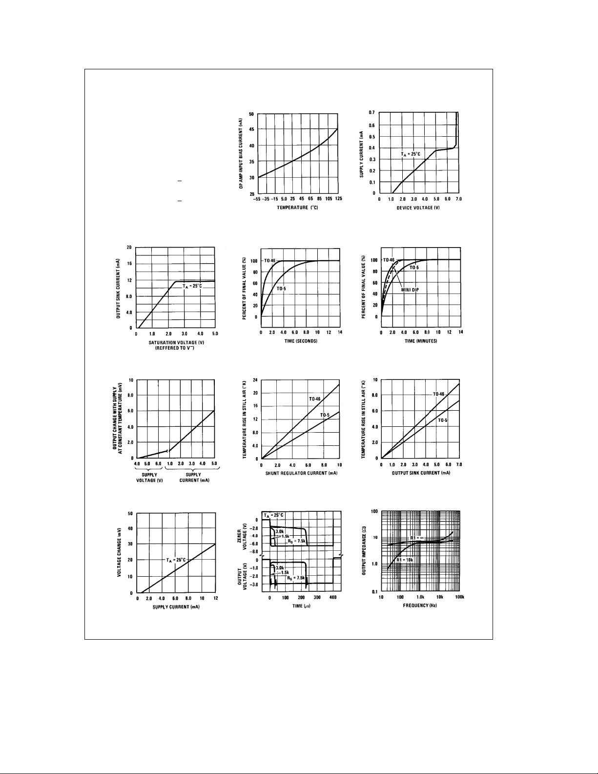
Typical Performance Characteristics
Temperature
Op Amp Input Current Power Supply Current
Conversion
e
T
K
a
T
273.16
C
(40aTF)
(40aTC)
e
T
C
e
T
F
5
b
40
9
9
b
40
5
Thermal Time Constant
in Stirred Oil Bath
Thermal Time Constant in
Still Air
T
CENTIGRADE
T
FAHRENHEIT
T
KELVIN
e
T
K
e
T
C
e
T
F
Output Saturation
Voltage
Supply Sensitivity Device Temperature Rise Device Temperature Rise
Reference Regulation Turn ‘‘ON’’ Response
3
Amplifier Output Impedance
TL/H/5701– 2
Page 4

Schematic Diagram
Typical Applications
(Continued)
Basic Thermometer for Negative Supply
Note: Load current to GND
is supplied through R
b
e
b
R
(V
6.8V)c103X
S
External Frequency Compensation
for Greater Stability when Driving
Capacitive Loads
Basic Thermometer
for Positive Supply
S
b
e
b
R
(V
6.8V)c103X
S
Operating With External Zener for
Lower Power Dissipation
*
Depends on Zener current.
4
Increasing Output Drive
a
e
b
R
(V
6.8V)c103X
S
Temperature Controller With Hysteresis
*Output goes positive on temperature increase
²
Set temperature
TL/H/5701– 3
Page 5

Typical Applications (Continued)
Thermometer With Meter Output
R1*
Select I
R2
R3
I
Q
#
V
z
DT
I
M
T
O
I
Q
*Values shown for:
T
O
I
M
**The 0.01 in the above and following equations is in units of V/
and is a result of the basic 0.01V/
Ground Referred Thermometer
R1
R2
R3
V
z
DT
T
O
V
O
I
Q
(VZ)(10mV)(DT)
e
V
O
R
0.01 T
e
V
Z
e
I
Q
e
e
e
e
e
b
b
I
Q
R2
0.01 TO)
IQR1
R2
e
Q
**
100 mA
(VZ) 0.01DT
e
IM(V
Z
2V
s
Q
R1
0.01 T
O
e
V
Z
e
bR1b
I
Q
2V
s
R1
J
e
Shunt regulator voltage (use 6.85)
e
Meter temperature span (§K)
e
Meter full scale current (A)
e
Meter zero temperature (§K)
e
Current through R1, R2, R3 at zero
meter current (10 mA to 1.0 mA) (A)
e
300§K, DTe100§K,
e
1.0 mA, I
K sensitivity of the transducer
§
b
(V
0.01 TO)
Z
L
b
IQR1
O
I
Q
bR1b
Shunt regulator voltage
Temperature span (§K)
Temperature for zero output (§K)
Full scale output voltages10V
Current through R1, R2, R3
at zero output voltage
(typically 100 mA to 1.0 mA)
Meter Thermometer With Trimmed Output
*Selected as for meter thermometer except TOshould
K more than desired and I
be 5
§
²
Calibrates T
KorV/§C,
§
O
Ground Referred Centigrade Thermometer
*Set zero
e
100 mA
Q
0.01 T
b
V
0.01 T
Z
T
H
Z
T
#
L
ILT
b
I
H
1
0.01 TL)(R2)
L
J#
0.01
R1 R3
b
1
J
H
T
L
%
e
1mAto10mAfor10§Fto100§F
OUT
#
e
R2 (X)
Two Terminal Temperature to Current Transducer*
V
t
R3(X)
1
e
b
R4
(V
Z
e
T
Temperature for IL(K)
L
e
Temperature for IH(K)
T
H
e
Zener voltage (V)
V
Z
e
Low temperature output current (A)
I
L
e
High temperature output current (A)
I
H
*Values shown for I
²
Set temperature
**The 0.01 in the above and following equations is in units of V/§KorV/§C, and is a result of the basic 0.01V/§K sensitivity of the transducer
b
I
H
R1
b
TH(V
Z
Ð
(R2)(0.01 TL)
R1
H
a
V
#
J
0.01 TL)bTL(V
V
Z
#
a
5
Z
b
b
0.01 T
R2
1
R2
0.01 T
b
Z
a
R3
H
0.01 TH)
L
b
1
J#
I
L
0.01 T
J
L
b
R1
(
1
b
R2
–
TL/H/5701– 4
**
I
L
J
Page 6

Typical Applications (Continued)
Over Temperature Detectors With Common Output
Trip PointeV
R
Two-Wire Remote A.C. Electronic Thermostat (Gas or Oil Furnace Control)
*Solenoid or 6b15W heater
²
Pot will provide about a 50§Fto90§F setting range. The trim resistor (100k) is selected
F near the middle of the pot rotation.
to bring 70
§
SCR heating, by proper positioning, can preheat the sensor giving control anticipation as is presently used in many home thermostats.
e
S
Z
a
b
(V
a
0.001 A
TL/H/5701– 5
TL/H/5701– 8
R1
R1aR2
6.8V)
6.8V
R1aR2
Electronic Thermostat
6
*Set temperature
²
SCR turns on power to fan or
cooler when temperature increases.
SENSITIVE GATE TRIAC
s
e
IG
5mA
T
RCA T2300, 40529
OR SIMILAR
TL/H/5701– 9
Page 7

Typical Applications (Continued)
Kelvin Thermometer With
Ground Referred Output
Three-Wire Electronic Thermostat
*Divider is set for a nominal 0§Cb125§C range.
Wire wound resistors will provide maximum
temperature stability.
**Almost any TRIAC rated 1 to 35 amperes
usable with appropriate load.
Differential Thermometer
a
b
V
6.8Vc103X
S
e
R
S
2
Connection Diagrams
a
R
R
1
e
V
0.01
OUT
Output can swing
with low output impedance
**The 0.01 in the above equation is in units of V/
of the basic 0.01 V/
2
b
(T
T1)**
2
R
#
J
1
g
3V atg50 mA
K sensitivity of the transducer
§
Dual-In-Line Package
Order Number LM3911N
TL/H/5701– 6
See NS Package N08E
7
KorV/§C, and is a result
§
TO-46 Package
Order Number LM3911H-46
See NS Package H04A
TL/H/5701– 7
Page 8

Physical Dimensions inches (millimeters)
LM3911 Temperature Controller
Molded Dual-In-Line Package (N)
Order Number LM3911N
NS Package N08E
TO-46 Package (H)
Order Number LM3911H-46
NS Package H04A
LIFE SUPPORT POLICY
NATIONAL’S PRODUCTS ARE NOT AUTHORIZED FOR USE AS CRITICAL COMPONENTS IN LIFE SUPPORT
DEVICES OR SYSTEMS WITHOUT THE EXPRESS WRITTEN APPROVAL OF THE PRESIDENT OF NATIONAL
SEMICONDUCTOR CORPORATION. As used herein:
1. Life support devices or systems are devices or 2. A critical component is any component of a life
systems which, (a) are intended for surgical implant support device or system whose failure to perform can
into the body, or (b) support or sustain life, and whose be reasonably expected to cause the failure of the life
failure to perform, when properly used in accordance support device or system, or to affect its safety or
with instructions for use provided in the labeling, can effectiveness.
be reasonably expected to result in a significant injury
to the user.
National Semiconductor National Semiconductor National Semiconductor National Semiconductor
Corporation Europe Hong Kong Ltd. Japan Ltd.
1111 West Bardin Road Fax: (
Arlington, TX 76017 Email: cnjwge@tevm2.nsc.com Ocean Centre, 5 Canton Rd. Fax: 81-043-299-2408
Tel: 1(800) 272-9959 Deutsch Tel: (
Fax: 1(800) 737-7018 English Tel: (
National does not assume any responsibility for use of any circuitry described, no circuit patent licenses are implied and National reserves the right at any time without notice to change said circuitry and specifications.
Fran3ais Tel: (
Italiano Tel: (
a
49) 0-180-530 85 86 13th Floor, Straight Block, Tel: 81-043-299-2309
a
49) 0-180-530 85 85 Tsimshatsui, Kowloon
a
49) 0-180-532 78 32 Hong Kong
a
49) 0-180-532 93 58 Tel: (852) 2737-1600
a
49) 0-180-534 16 80 Fax: (852) 2736-9960
 Loading...