

Page 1
TL/H/7969
LM3909 LED Flasher/Oscillator
February 1995
LM3909 LED Flasher/Oscillator
General Description
The LM3909 is a monolithic oscillator specifically designed
to flash Light Emitting Diodes. By using the timing capacitor
for voltage boost, it delivers pulses of 2 or more volts to the
LED while operating on a supply of 1.5V or less. The circuit
is inherently self-starting, and requires addition of only a battery and capacitor to function as an LED flasher.
Packaged in an 8-lead plastic mini-DIP, the LM3909 will operate over the extended consumer temperature range of
b
25§Ctoa70§C. It has been optimized for low power drain
and operation from weak batteries so that continuous operation life exceeds that expected from battery rating.
Application is made simple by inclusion of internal timing
resistors and an internal LED current limit resistor. As
shown in the first two application circuits, the timing resistors supplied are optimized for nominal flashing rates and
minimum power drain at 1.5V and 3V.
Timing capacitors will generally be of the electrolytic type,
and a small 3V rated part will be suitable for any LED flasher
using a supply up to 6V. However, when picking flash rates,
it should be remembered that some electrolytics have very
broad capacitance tolerances, for example
b
20% to
a
100%.
Features
Y
Operation over one year from one C size flashlight cell
Y
Bright, high current LED pulse
Y
Minimum external parts
Y
Low cost
Y
Low voltage operation, from just over 1V to 5V
Y
Low current drain, averages under 0.5 mA during
battery life
Y
Powerful; as an oscillator directly drives an 8X speaker
Y
Wide temperature range
Applications
Y
Finding flashlights in the dark, or locating boat mooring
floats
Y
Sales and advertising gimmicks
Y
Emergency locators, for instance on fire extinguishers
Y
Toys and novelties
Y
Electronic applications such as trigger and sawtooth
generators
Y
Siren for toy fire engine, (combined oscillator, speaker
driver)
Y
Warning indicators powered by 1.4V to 200V
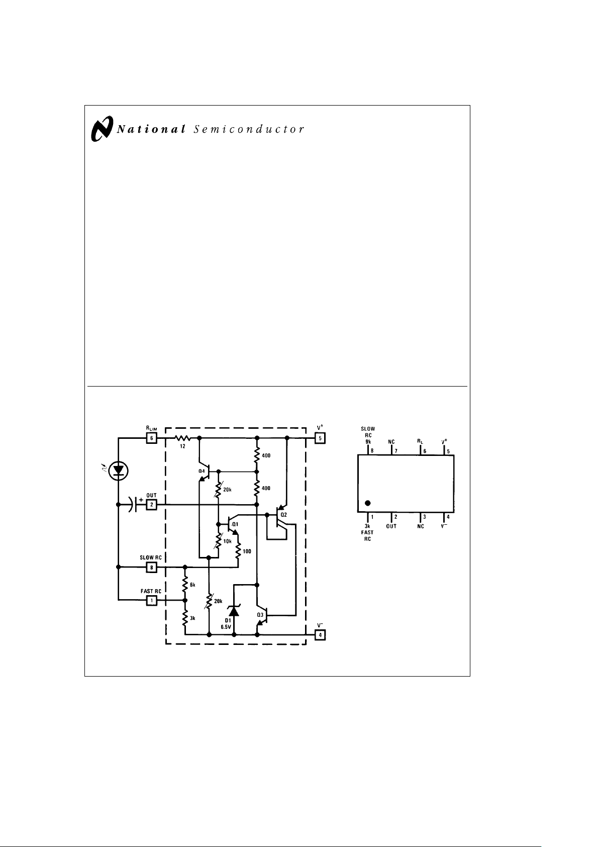
Schematic Diagram
Typical 1.5V Flasher
TL/H/7969– 1
Connection Diagram
Dual-In-Line Package
TL/H/7969– 2
Top View
Order Number LM3909N
See NS Package Number N08E
C
1995 National Semiconductor Corporation RRD-B30M115/Printed in U. S. A.
Page 2
Absolute Maximum Ratings
If Military/Aerospace specified devices are required,
please contact the National Semiconductor Sales
Office/Distributors for availability and specifications.
Power Dissipation 500 mW
V
a
Voltage 6.4V
Operating Temperature Range
b
25§Ctoa70§C
Lead Temperature (Soldering, 10 sec.) 260§C
Electrical Characteristics
Parameter
Conditions
Min Typ Max Units
(Applications Note 3)
Supply Voltage (In Oscillation) 1.15 6.0 V
Operating Current 0.55 0.75 mA
Flash Frequency 300 mF, 5% Capacitor 0.65 1.0 1.3 Hz
High Flash Frequency 0.30 mF, 5% Capacitor 1.1 kHz
Compatible LED Forward Drop 1 mA Forward Current 1.35 2.1 V
Peak LED Current 350 mF Capacitor 45 mA
Pulse Width 350 mF Capacitors at (/2 Amplitude 6.0 ms
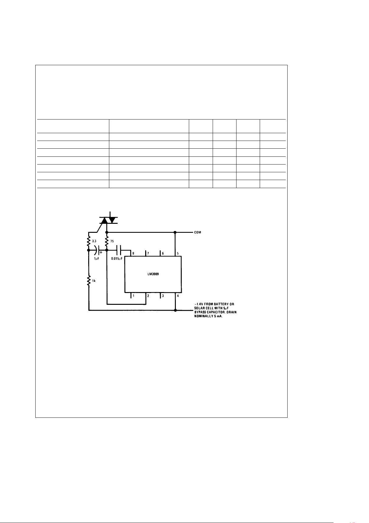
Typical Applications (See applications notes on following page)
Triac Trigger
Provides 40 mA. 10 ms pulses at about 8 kHz.
Triac gate may be pulse transformer isolated if
desired.
TL/H/7969– 3
2
Page 3
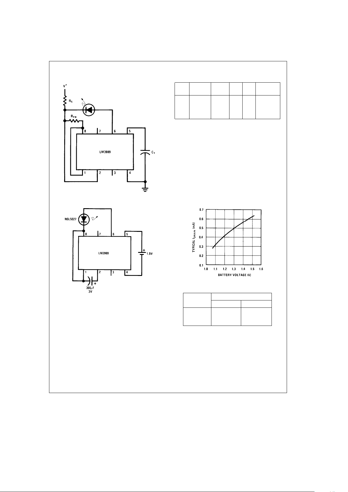
Typical Applications (Continued)(See applications notes below)
Warning Flasher High Voltage Powered
TL/H/7969– 4
Typical Operating Conditions
V
a
Nominal
C
T
RSRFBV
a
RANGE
Flash Hz
6V 2 400 mF 1k 1.5k 5V – 25V
15V 2 180 mF 3.9k 1k 13V–50V
100V 1.7 180 mF
43k
1k 85V– 200V
1W
1.5V Flasher
TL/H/7969– 5
Note: Nominal flash rate: 1 Hz.
TL/H/7969– 6
Estimated Battery Life
(Continuous 1.5V Flasher Operation)
Size Cell
Type
Standard Alkaline
AA 3 months 6 months
C 7 months 15 months
D 1.3 years 2.6 years
Note: Estimates are made from our tests and manufacturers
data. Conditions are fresh batteries and room temperature. Clad
or ‘‘leak-proof’’ batteries are recommended for any application
of five months or more. Nickel Cadmium cells are not recommended.
APPLICATIONS NOTES
Note 1: All capacitors shown are electrolytic unless marked otherwise.
Note 2: Flash rates and frequencies assume a
g
5% capacitor tolerance. Electrolytics may varyb20% toa100% of their stated value.
Note 3: Unless noted, measurements above are made with a 1.4V supply, a 25
§
C ambient temperature, and an LED with a forward drop of 1.5V to 1.7V at 1 mA
forward current.
Note 4: Occasionally a flasher circuit will fail to oscillate due to an LED defect that may be missed because it only reduces light output 10% or so. Such LEDs can
be identified by a large increase in conduction between 0.9V and 1.2V.
3
Page 4

Typical Applications (Continued) (See applications notes on previous page)
3V Flasher
TL/H/7969– 7
Note: Nominal flash rate: 1 Hz. Average I
DRAIN
e
0.77 mA.
Minimum Power at 1.5V
TL/H/7969– 8
Note: Nominal flash rate: 1.1 Hz. Average I
DRAIN
e
0.32 mA.
Fast Blinker
TL/H/7969– 9
Note: Nominal flash rate: 2.6 Hz. Average I
DRAIN
e
1.2 mA.
TL/H/7969– 11
Note: Winking LED inside, locates light in total darkness.
4
Page 5

Typical Applications (Continued) (See applications notes above)
Flashlight Finder
TL/H/7969– 10
Note: LM3909, capacitor, and LED are installed in a white translucent cap on the flashlight’s back end. Only one
contact strip (in addition to the case connection) is needed for flasher power. Drawing current through the bulb
simplifies wiring and causes negligible loss since bulb resistance cold is typically less than 2X.
4 Parallel LEDs
TL/H/7969– 12
Note: Nominal flash rate: 1.3 Hz. Average I
DRAIN
e
2 mA.
High Efficiency Parallel Circuit
TL/H/7969– 13
Note: Nominal flash rate: 1.5 Hz. Average I
DRAIN
e
1.5 mA.
5
Page 6

Typical Applications (Continued) (See applications notes above)
1 kHz Square Wave
TL/H/7969– 14
TL/H/7969– 15
Note: Output voltage through a 10k load to ground.
‘‘Buzz Box’’ Continuity and Coil Checker
TL/H/7969– 16
Note: Differences between shorts, coils, and a few ohms of resistance can be
heard.
Variable Flasher
TL/H/7969– 17
Note: Flash rate: 0 Hz– 20 Hz.
6
Page 7

Typical Applications (Continued) (See applications notes above)
LED Booster
TL/H/7969– 18
Note: High efficiency, 4 mA drain. Continuous appearing light obtained by supplying
short, high current, pulses (2 kHz) to LEDs with higher than battery voltage available.
Incandescent Bulb Flasher
TL/H/7969– 19
Note: Flash rate: 1.5 Hz.
Emergency Lantern/Flasher
TL/H/7969– 20
Note: Nominal flash rate: 1.5 Hz.
7
Page 8

LM3909 LED Flasher/Oscillator
Physical Dimensions inches (millimeters)
Molded Dual-In-Line Package (N)
Order Number LM3909N
NS Package Number N08E
LIFE SUPPORT POLICY
NATIONAL’S PRODUCTS ARE NOT AUTHORIZED FOR USE AS CRITICAL COMPONENTS IN LIFE SUPPORT
DEVICES OR SYSTEMS WITHOUT THE EXPRESS WRITTEN APPROVAL OF THE PRESIDENT OF NATIONAL
SEMICONDUCTOR CORPORATION. As used herein:
1. Life support devices or systems are devices or 2. A critical component is any component of a life
systems which, (a) are intended for surgical implant support device or system whose failure to perform can
into the body, or (b) support or sustain life, and whose be reasonably expected to cause the failure of the life
failure to perform, when properly used in accordance support device or system, or to affect its safety or
with instructions for use provided in the labeling, can effectiveness.
be reasonably expected to result in a significant injury
to the user.
National Semiconductor National Semiconductor National Semiconductor National Semiconductor
Corporation Europe Hong Kong Ltd. Japan Ltd.
1111 West Bardin Road Fax: (
a
49) 0-180-530 85 86 13th Floor, Straight Block, Tel: 81-043-299-2309
Arlington, TX 76017 Email: cnjwge@tevm2.nsc.com Ocean Centre, 5 Canton Rd. Fax: 81-043-299-2408
Tel: 1(800) 272-9959 Deutsch Tel: (
a
49) 0-180-530 85 85 Tsimshatsui, Kowloon
Fax: 1(800) 737-7018 English Tel: (
a
49) 0-180-532 78 32 Hong Kong
Fran3ais Tel: (
a
49) 0-180-532 93 58 Tel: (852) 2737-1600
Italiano Tel: (
a
49) 0-180-534 16 80 Fax: (852) 2736-9960
National does not assume any responsibility for use of any circuitry described, no circuit patent licenses are implied and National reserves the right at any time without notice to change said circuitry and specifications.
 Loading...