

Page 1
LM185/LM285/LM385
Adjustable Micropower Voltage References
General Description
The LM185/LM285/LM385 are micropower 3-terminal adjustable band-gap voltage reference diodes. Operating from
1.24 to 5.3V and over a 10µA to 20mA current range, they
feature exceptionallylow dynamic impedance and good temperature stability. On-chip trimming is used to provide tight
voltage tolerance. Since the LM185 band-gap reference
uses only transistors and resistors, low noise and good
long-term stability result.
Careful designof the LM185 has made the device tolerant of
capacitive loading, making it easy to use in almost any reference application. The wide dynamic operating range allows
its use with widely varying supplies with excellent regulation.
The extremely low power drain of the LM185 makes it useful
for micropower circuitry. This voltage reference can be used
to makeportable meters, regulators or general purpose analog circuitry with battery life approaching shelf life. Further,
the wide operating current allows it to replace older references with a tighter tolerance part.
The LM185 is rated for operation over a −55˚C to 125˚C temperature range, while the LM285 is rated −40˚C to 85˚C and
the LM385 0˚C to 70˚C. The LM185 is available in a hermetic
TO-46 package and a leadless chip carrier package, while
the LM285/LM385 are available in a low-cost TO-92 molded
package, as well as S.O.
Features
n Adjustable from 1.24V to 5.30V
n Operating current of 10µA to 20mA
n 1%and 2%initial tolerance
n 1Ω dynamic impedance
n Low temperature coefficient
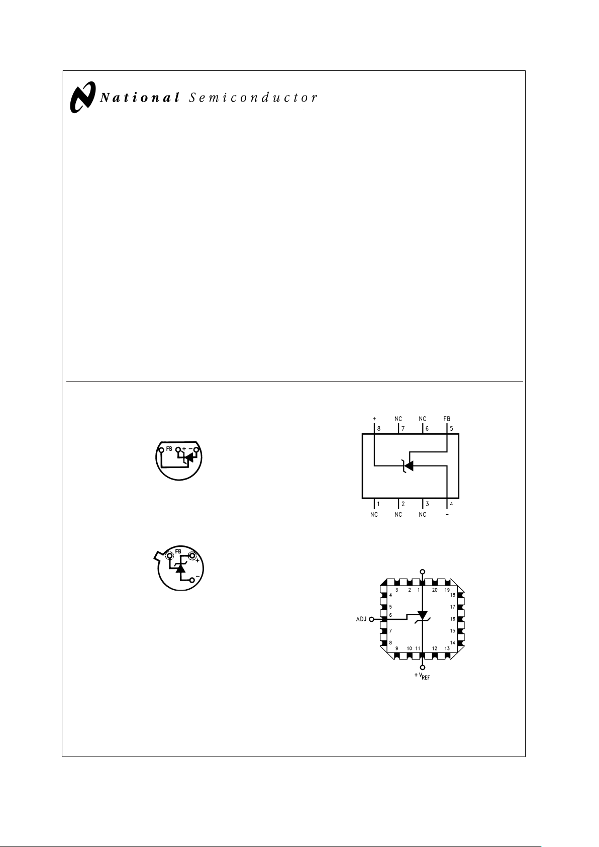
Connection Diagrams
TO-92
Plastic Package
DS005250-9
Bottom View
TO-46
Metal Can Package
DS005250-1
Bottom View
SOIC Package
DS005250-10
Top View
20-Leadless Chip Carrier
DS005250-15
Top View
February 2000
LM185/LM285/LM385 Adjustable Micropower Voltage Reference
© 2000 National Semiconductor Corporation DS005250 www.national.com
Page 2
Ordering Information
Package Temperature Range NSC
Drawing
−55˚C to 125˚C −40˚C to 85˚C 0˚C to 70˚C
TO-46
LM185BH
H03H
LM185BH/883
LM185BYH
LM185BYH/883
TO-92
LM285BXZ LM385BXZ
Z03A
LM285BYZ LM385BYZ
LM285Z LM385BZ
LM385Z
8-Pin SOIC
LM285M LM385M
M08A
LM285BYM LM385BM
20-Leadless Chip
Carrier
LM185BE/883
E20A
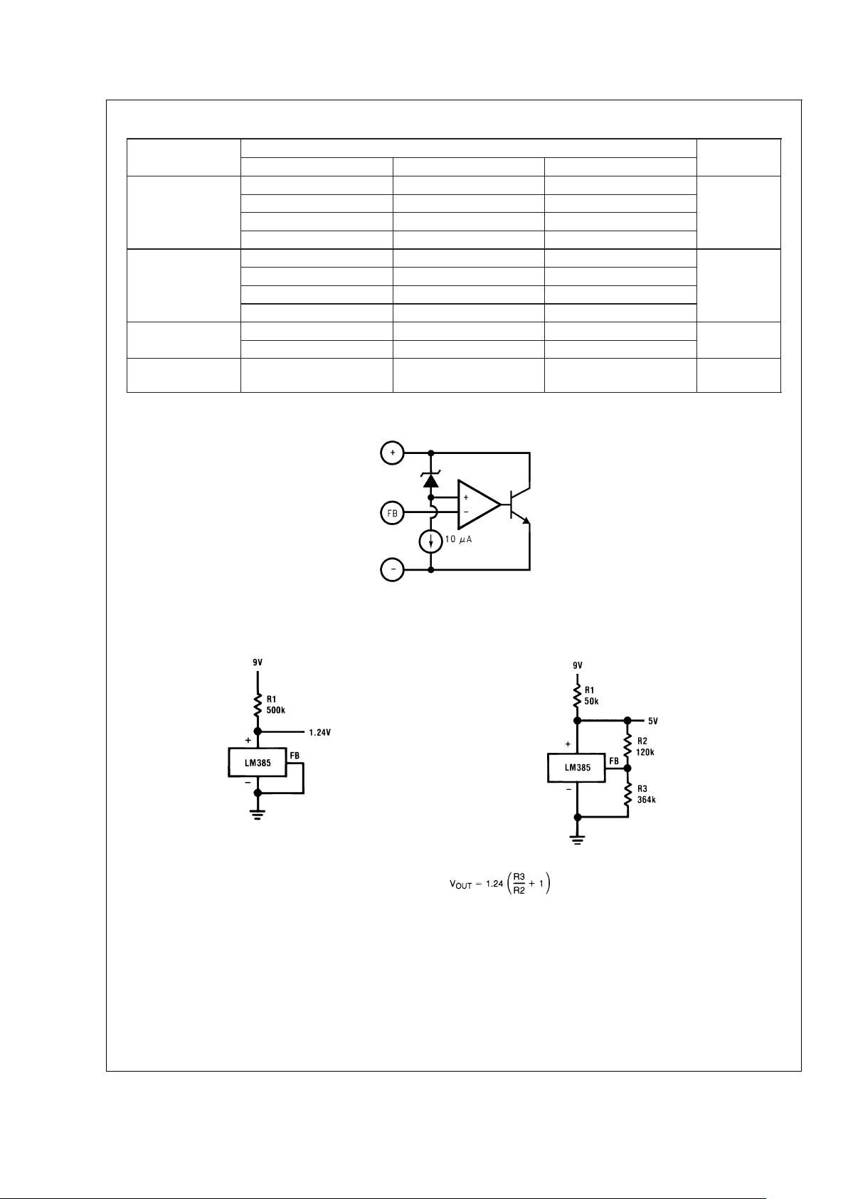
Block Diagram
Typical Applications
DS005250-13
1.2V Reference
DS005250-14
5.0V Reference
DS005250-2
LM185/LM285/LM385
www.national.com 2
Page 3
Absolute Maximum Ratings (Note 1)
If Military/Aerospace specified devices are required,
please contact the National Semiconductor SalesOffice/
Distributors for availability and specifications.
(Note 2)
Reverse Current 30mA
Forward Current 10mA
Operating Temperature Range (Note 3)
LM185 Series −55˚C to 125˚C
LM285 Series −40˚C to 85˚C
LM385 Series 0˚C to 70˚C
Storage Temperature −55˚C to 150˚C
Soldering Information
TO-92 Package (10 sec.) 260˚C
TO-46 Package (10 sec.) 300˚C
SO Package
Vapor Phase (60 sec.) 215˚C
Infrared (15 sec.) 220˚C
See An-450 “Surface Mounting Methods and Their Effect
on Product Reliability” for other methods of soldering
surface mount devices.
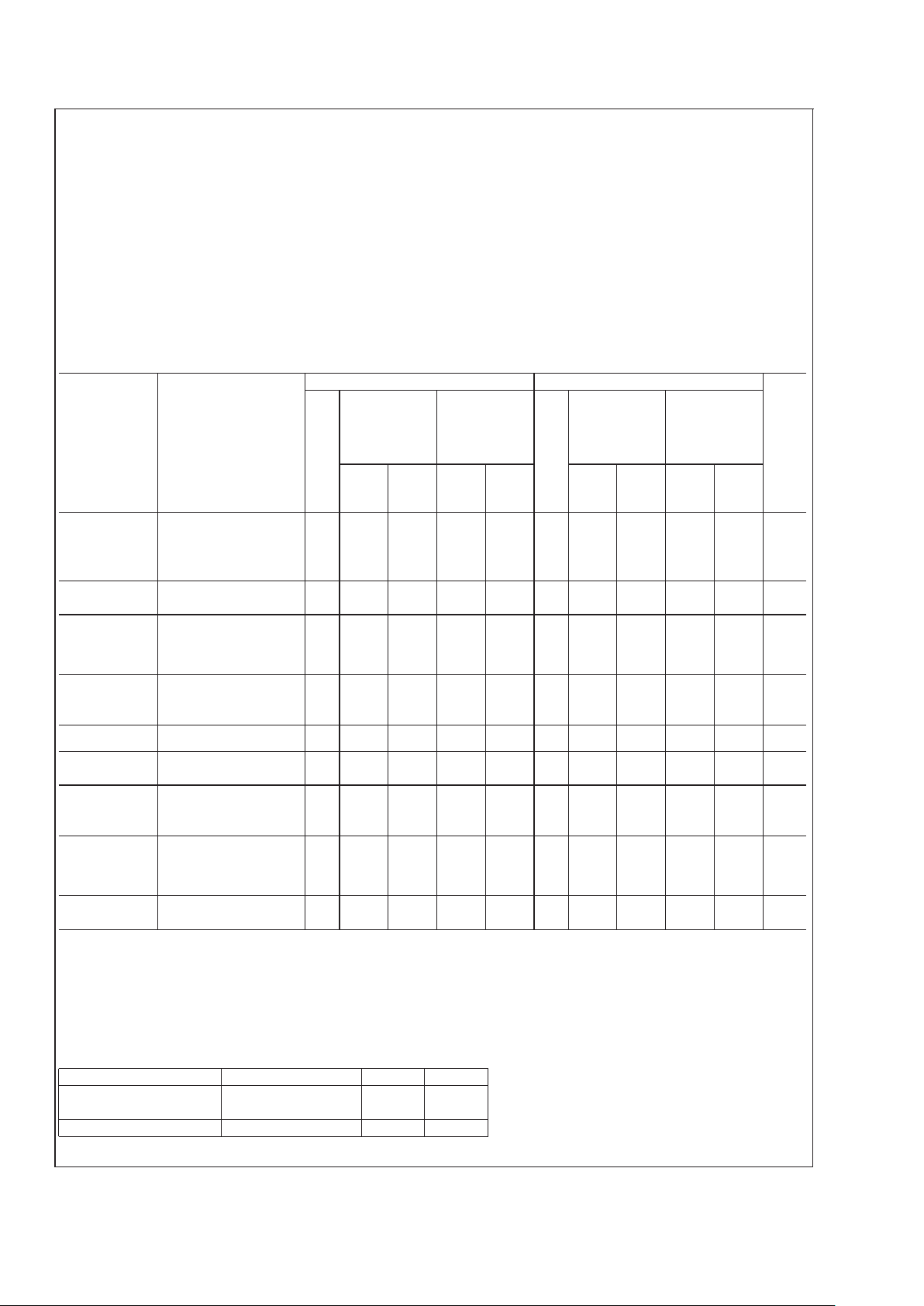
Electrical Characteristics (Note 4)
Parameter Conditions
LM185, LM285 LM385
Typ
LM185BX,
LM185BY
Typ
LM385BX,
LM185B,
LM285BX,
LM285
LM385BY
LM385
Units
LM285BY (Limit)
Tested Design Tested Design Tested Design Tested Design
Limit Limit Limit Limit Limit Limit Limit Limit
(Note 5) (Note 6) (Note 5) (Note 6) (Note 5) (Note 6) (Note 5) (Note 6)
Reference Voltage I
R
=
100µA 1.240 1.252 1.265 1.270 1.240 1.252 1.255 1.265 1.270 V
1.255 (max)
1.228 1.215 1.205 1.228 1.215 1.215 1.205 V
1.215 (min)
Reference Voltage I
MIN
<
I
R
<
1mA 0.2 1 1.5 1 1.5 0.2 1 1.5 1 1.5 mV
Change with Current 1mA
<
I
R
<
20mA 4 10 20 10 20 515 25 15 25 (max)
Dynamic Output I
R
=
100µA, f=100Hz
Impedance I
AC
=
0.1 I
R
V
OUT
=
V
REF
0.3 0.4
Ω
V
OUT
=
5.3V 0.7 1
Reference Voltage I
R
=
100µA mV
Change with Output 1 3 6 3 6 25 10 5 10 (max)
Voltage
Feedback Current 13 20 25 20 25 16 30 35 30 35 nA
(max)
Minimum Operating V
OUT
=
V
REF
69 10 9 10 711 13 11 13 µA
Current (see curve) V
OUT
=
5.3V 30 45 50 45 50 35 55 60 55 60 (max)
Output Wideband I
R
=
100µA, 10Hz
<f<
10kHz
Noise V
OUT
=
V
REF
50 50 µV
rms
V
OUT
=
5.3V 170 170
Average
Temperature
I
R
=
100µA X Suffix 30 30 ppm/˚c
Coefficient (Note 7) Y Suffix 50 50 (max)
All Others 150 150 150 150
Long Term Stability I
R
=
100µA, T=1000 Hr, 20 20 ppm
T
A
=
25˚C
±
0.1˚C
Note 1: Absolute Maximum Ratings indicate limits beyond which damage to the device may occur. Operating Ratings indicate conditions for which the device is intended to be functional, but do not guarantee specific performance limits. For guaranteed specifications and test conditions, see the Electrical Characteristics. The
guaranteed specifications apply only for the test conditions listed.
Note 2: Refer to RETS185H for military specifications.
Note 3: For elevated temperature operation, T
J
max is:
LM185 150˚C
LM285 125˚C
LM385 100˚C
Thermal Resistance TO-92 TO-46 SO-8
θ
JA
(Junction to Ambient) 180˚C/W (0.4" leads) 440˚C/W 165˚C/W
170˚C/W (0.125" leads)
θ
JC
(Junction to Case) N/A 80˚C/W N/A
LM185/LM285/LM385
www.national.com3
Page 4
Electrical Characteristics (Note 4) (Continued)
Note 4: Parameters identifiedwith boldface type apply at temperature extremes.Allother numbers apply atT
A
=
T
J
=
25˚C. Unless otherwise specified, all param-
eters apply for V
REF
<
V
OUT
<
5.3V.
Note 5: Guaranteed and 100%production tested.
Note 6: Guaranteed, but not 100%production tested. These limits are not to be used to calculate average outgoing quality levels.
Note 7: The average temperature coefficient is defined as the maximum deviation of reference voltage at all measured temperatures from T
MIN
to T
MAX
, divided by
T
MAX−TMIN
. The measured temperatures are −55, −40, 0, 25, 70, 85, 125˚C.
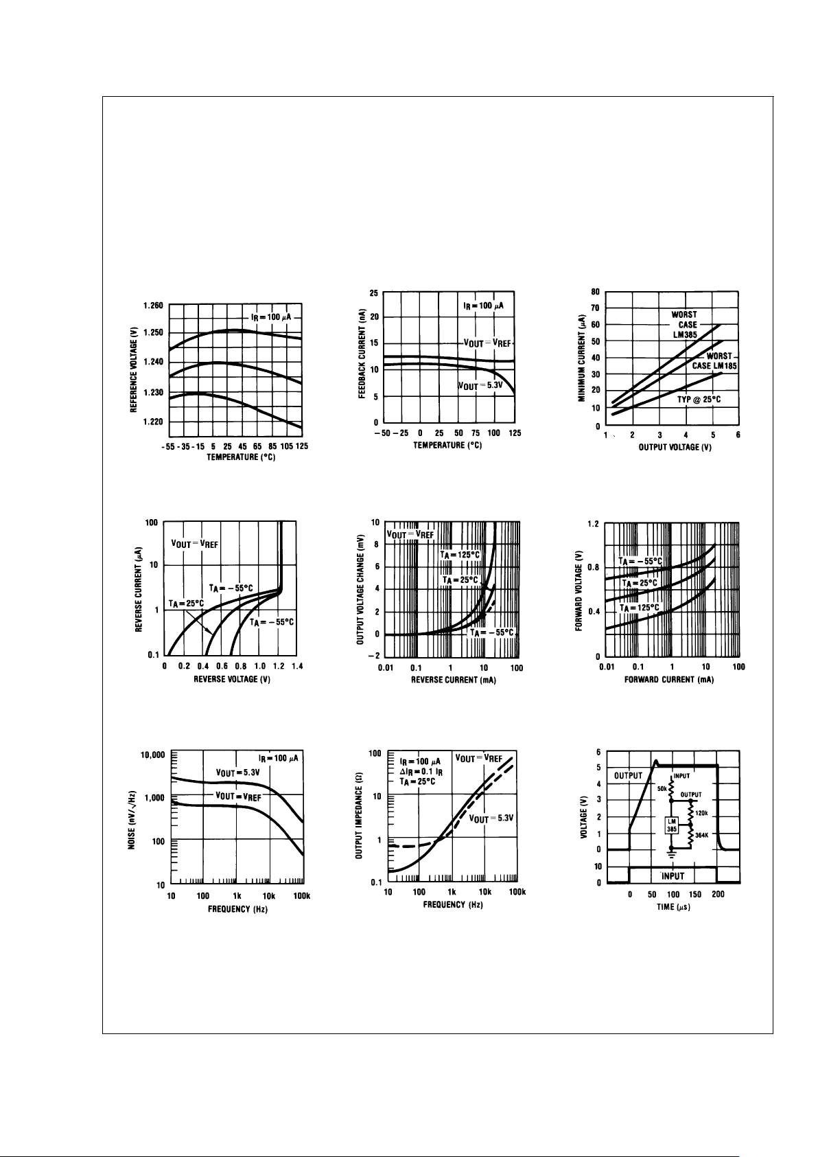
Typical Performance Characteristics
Temperature Drift of 3
Representative Units
DS005250-16
Feedback Current
DS005250-17
Minimum Operating Current
DS005250-18
Reverse Characteristics
DS005250-19
Reverse Characteristics
DS005250-20
Forward Characteristics
DS005250-21
Output Noise Voltage
DS005250-22
Dynamic Output Impedance
DS005250-23
Response Time
DS005250-24
LM185/LM285/LM385
www.national.com 4
Page 5

Typical Performance Characteristics (Continued)
Typical Applications
Temperature Coefficient Typical
LM185 LM285 LM385
DS005250-4
Precision 10V Reference
DS005250-25
Low AC Noise Reference
DS005250-26
25V Low Current Shunt Regulator
DS005250-27
200 mA Shunt Regulator
DS005250-28
LM185/LM285/LM385
www.national.com5
Page 6

Typical Applications (Continued)
Series-Shunt 20 mA Regulator
DS005250-29
High Efficiency Low Power Regulator
DS005250-30
Voltage Level Detector
DS005250-31
Voltage Level Detector
DS005250-32
Fast Positive Clamp
2.4V + ∆V
D1
DS005250-33
Bidirectional Clamp
±
2.4V
DS005250-34
LM185/LM285/LM385
www.national.com 6
Page 7

Typical Applications (Continued)
Bidirectional Adjustable Clamp
±
1.8V to±2.4V
DS005250-35
Bidirectional Adjustable Clamp
±
2.4V to±6V
DS005250-36
Simple Floating Current Detector
DS005250-37
Current Source
DS005250-38
LM185/LM285/LM385
www.national.com7
Page 8

Typical Applications (Continued)
Precision Floating Current Detector
DS005250-39
*D1 can be any LED, V
F
=
1.5V to 2.2V at 3 mA. D1 may act as an indicator. D1 will be on if I
THRESHOLD
falls below the threshold current, except with I=O.
Centigrade Thermometer, 10mV/˚C
DS005250-11
Freezer Alarm
DS005250-12
LM185/LM285/LM385
www.national.com 8
Page 9

Schematic Diagram
DS005250-8
LM185/LM285/LM385
www.national.com9
Page 10

Physical Dimensions inches (millimeters) unless otherwise noted
20-Leadless Chip Carrier (E)
NS Package Number E20A
TO-46 Metal Can Package (H)
NS Package Number H03H
LM185/LM285/LM385
www.national.com 10
Page 11

Physical Dimensions inches (millimeters) unless otherwise noted (Continued)
SO Package (M)
NS Package Number M08A
TO-92 Plastic Package (Z)
NS Package Number Z03A
LM185/LM285/LM385
www.national.com11
Page 12

Notes
LIFE SUPPORT POLICY
NATIONAL’S PRODUCTS ARE NOT AUTHORIZED FOR USE AS CRITICAL COMPONENTS IN LIFE SUPPORT
DEVICES OR SYSTEMS WITHOUT THE EXPRESS WRITTEN APPROVAL OF THE PRESIDENT AND GENERAL
COUNSEL OF NATIONAL SEMICONDUCTOR CORPORATION. As used herein:
1. Life support devices or systems are devices or
systems which, (a) are intended for surgical implant
into the body, or (b) support or sustain life, and
whose failure to perform when properly used in
accordance with instructions for use provided in the
labeling, can be reasonably expected to result in a
significant injury to the user.
2. A critical component is any component of a life
support device or system whose failure to perform
can be reasonably expected to cause the failure of
the life support device or system, or to affect its
safety or effectiveness.
National Semiconductor
Corporation
Americas
Tel: 1-800-272-9959
Fax: 1-800-737-7018
Email: support@nsc.com
National Semiconductor
Europe
Fax: +49 (0) 180-530 85 86
Email: europe.support@nsc.com
Deutsch Tel: +49 (0) 69 9508 6208
English Tel: +44 (0) 870 24 0 2171
Français Tel: +33 (0) 1 41 91 8790
National Semiconductor
Asia Pacific Customer
Response Group
Tel: 65-2544466
Fax: 65-2504466
Email: ap.support@nsc.com
National Semiconductor
Japan Ltd.
Tel: 81-3-5639-7560
Fax: 81-3-5639-7507
www.national.com
LM185/LM285/LM385 Adjustable Micropower Voltage Reference
National does not assume any responsibility for use of any circuitry described, no circuit patent licenses are implied and National reserves the right at any time without notice to change said circuitry and specifications.
 Loading...