

Page 1

Features
■ Dual MOSFET driver for synchronous rectified
converters
■ High driving current for fast external MOSFET
switching
■ High frequency operation
■ Integrated bootstrap diode
■ Adaptive dead-time management
■ Flexible gate-drive: 5V to 12V compatible
■ High-impedance (HiZ) management for output
stage shutdown
■ Preliminary OV protection
■ SO-8 package
Applications
■ High current VRM / VRD for Desktop / Server /
Workstation CPUs
■ High current DC / DC converters
L6741
High current MOSFET driver
SO-8
Description
L6741 is a flexible, high-frequency dual-driver
specifically designed to drive N-channel
MOSFETs connected in Synchronous-Rectified
Buck topology. Combined with ST PWM
controllers, the driver allows implementing
complete voltage regulator solutions for modern
high-current CPUs. L6741 embeds high-current
drivers for both high-side and low-side
MOSFETS. The device accepts flexible power
supply (5V to 12V) to optimize the gate-drive
voltage for High-Side and Low-Side maximizing
the System Efficiency.
The Bootstrap diode is embedded saving the use
of external diodes. Anti shoot-through
management avoids high-side and low-side
mosfet to conduct simultaneously and, combined
with Adaptive Dead-Time control, minimizes the
LS body diode conduction time.
L6741 embeds Preliminary OV Protection: after
Vcc overcomes the UVLO and while the device is
in HiZ, the Low-Side MOSFET is turned ON to
protect the load in case the output voltage
overcomes a warning threshold protecting the
load from High-Side MOSFET failures.
The driver is available is SOP8 package.
Table 1. Device summary
Order code Package Packaging
L6741 SO-8 Tube
L6741TR SO-8 Tape & Reel
August 2007 Rev 1 1/16
www.st.com
1
Page 2

Contents L6741
Contents
1 Typical application circuit and block diagram . . . . . . . . . . . . . . . . . . . . 3
1.1 Application circuit . . . . . . . . . . . . . . . . . . . . . . . . . . . . . . . . . . . . . . . . . . . . 3
1.2 Block diagram . . . . . . . . . . . . . . . . . . . . . . . . . . . . . . . . . . . . . . . . . . . . . . . 3
2 Pins description and connection diagrams . . . . . . . . . . . . . . . . . . . . . . 4
2.1 Pin description . . . . . . . . . . . . . . . . . . . . . . . . . . . . . . . . . . . . . . . . . . . . . . 4
3 Thermal data . . . . . . . . . . . . . . . . . . . . . . . . . . . . . . . . . . . . . . . . . . . . . . . 5
4 Electrical specifications . . . . . . . . . . . . . . . . . . . . . . . . . . . . . . . . . . . . . . 5
4.1 Absolute maximum ratings . . . . . . . . . . . . . . . . . . . . . . . . . . . . . . . . . . . . . 5
4.2 Electrical characteristics . . . . . . . . . . . . . . . . . . . . . . . . . . . . . . . . . . . . . . . 5
5 Device description and operation . . . . . . . . . . . . . . . . . . . . . . . . . . . . . . 7
5.1 High-impedance (HiZ) management . . . . . . . . . . . . . . . . . . . . . . . . . . . . . 8
5.2 Preliminary OV protection . . . . . . . . . . . . . . . . . . . . . . . . . . . . . . . . . . . . . 8
5.3 Internal BOOT diode . . . . . . . . . . . . . . . . . . . . . . . . . . . . . . . . . . . . . . . . . 8
5.4 Gate driver voltage flexibility . . . . . . . . . . . . . . . . . . . . . . . . . . . . . . . . . . . . 9
5.5 Power dissipation . . . . . . . . . . . . . . . . . . . . . . . . . . . . . . . . . . . . . . . . . . . . 9
5.6 Layout guidelines . . . . . . . . . . . . . . . . . . . . . . . . . . . . . . . . . . . . . . . . . . . 11
6 Package mechanical data . . . . . . . . . . . . . . . . . . . . . . . . . . . . . . . . . . . . 13
7 Revision history . . . . . . . . . . . . . . . . . . . . . . . . . . . . . . . . . . . . . . . . . . . 15
2/16
Page 3
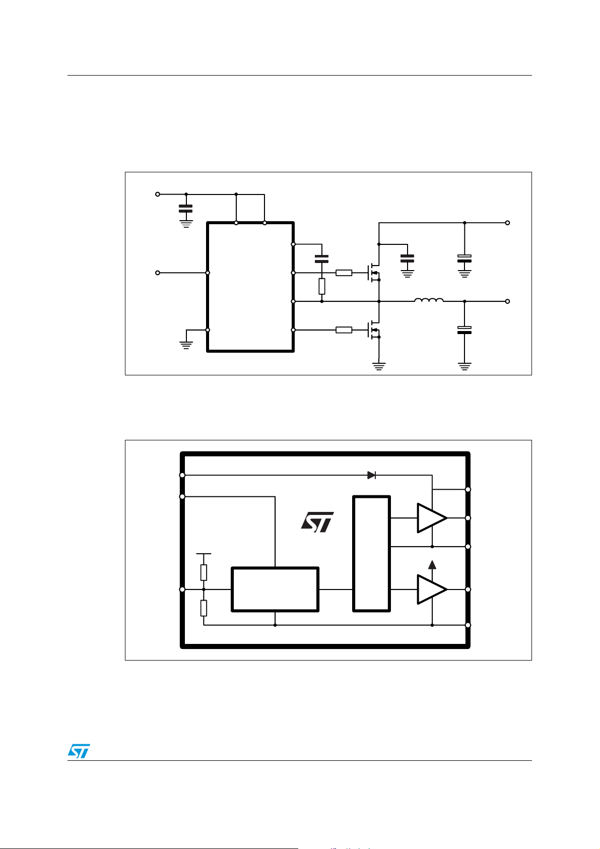
L6741 Typical application circuit and block diagram
1 Typical application circuit and block diagram
1.1 Application circuit
Figure 1. Typical application circuit
VCC = 5V to 12V
C
PWM Input
3
DEC
PWM
VCC
6
PVCC
BOOT
UGATE
7
2
C
1
HS
HF
VIN = 5V to 12V
C
BULK
4
GND
L6741 Reference Schematic
1.2 Block diagram
Figure 2. Block diagram
PVCC
VCC
PWM
PHASE
L6741
LGATE
8
5
L6741
CONTROL LOGIC
& PROTECTIONS
PWM
L
LS
CROSS CONDUCTION
ADAPTIVE ANTI
HS
VCC
LS
Vout
C
OUT
BOOT
UGATE
PHASE
LGATE
GND
3/16
Page 4
Pins description and connection diagrams L6741
2 Pins description and connection diagrams
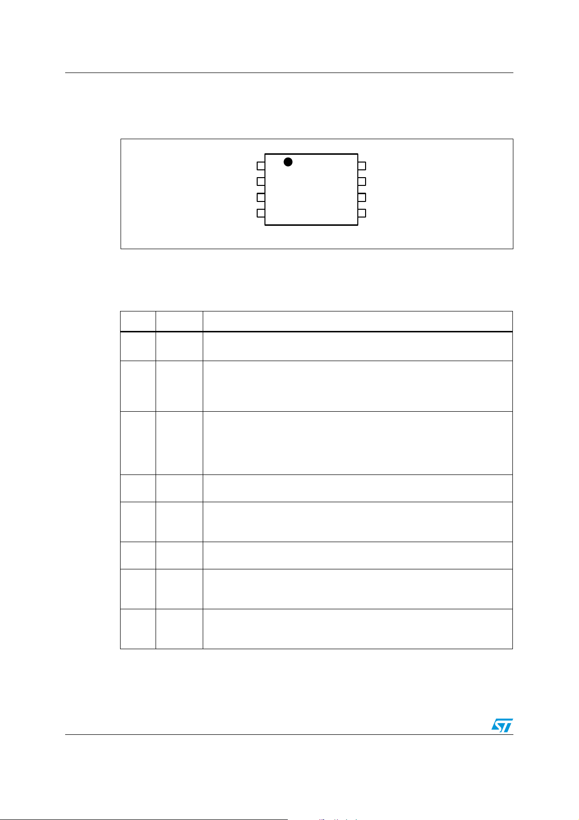
Figure 3. Pins connection (Top view)
2.1 Pin description
Table 2. Pins descriptions
Pin n Name Function
1UGATE
2BOOT
3PWM
4GND
High-side driver output.
Connect to High-Side MOSFET gate.
High-side driver supply. this pin supplies the high-side floating driver. Connect
through a R
Internally connected to the cathode of the integrated Bootstrap diode. See
Section 5.3 for guidance in designing the capacitor value.
Control input for the driver (5V compatible).
This pin controls the state of the driver and which external MOSFET have to be
turned-ON.
If left floating, it causes the driver to enter the High-Impedance (HiZ) state
which causes all mosfets to be OFF. See Section 5.1 for details about HiZ.
All internal references, logic and drivers are referenced to this pin. Connect to
the PCB ground plane.
UGATE
BOOT
PWM
GND
BOOT
1
2
3
4
- C
8
7
L6741
capacitor to the PHASE pin.
BOOT
6
5
PHASE
PVCC
VCC
LGATE
Low-side driver output.
5LGATE
6VCC
7 PVCC
8 PHASE
4/16
Connect directly to the Low-Side MOSFET gate. A small series resistor can be
useful to reduce dissipated power especially in high frequency applications.
Device and LS driver power supply. Connect to any voltage between 5V and
12V. Bypass with low-ESR MLCC capacitor to GND.
Integrated bootstrap diode anode supply.
Connect to any voltage between 5V and 12V to supply the HS driver
accordingly.
High-side driver return path. Connect to the high-side MOSFET source.
This pin is also monitored for the adaptive dead-time management and Pre-OV
protection.
Page 5
L6741 Thermal data
3 Thermal data
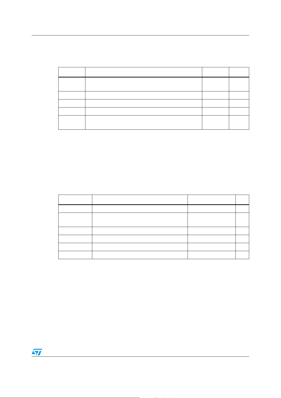
Table 3. Thermal data
Symbol Parameter Value Unit
R
T
T
P
thJA
MAX
STG
T
J
TOT
Thermal resistance junction to ambient
(Device soldered on 2s2p PC Board - 67mm x 67mm)
Maximum junction temperature 150 °C
Storage temperature range 0 to 150 °C
Junction temperature range 0 to 125 °C
Maximum power dissipation at 25°C
(Device soldered on 2s2p PC Board)
4 Electrical specifications
4.1 Absolute maximum ratings
Table 4. Absolute maximum ratings
Symbol Parameter Value Unit
V
CC,VPVCC
, V
V
BOOT
V
PHASE
V
LGATE
V
PWM
V
CC,VPVCC
UGATE
to GND -0.3 to 15 V
to GND
to PHASE
to GND -8 to 26 V
to GND -0.3 to VCC + 0.3 V
to GND -0.3 to 7 V
to GND -0.3 to 15 V
85 °C/W
1.15 W
41
15
V
5/16
Page 6
Electrical specifications L6741
4.2 Electrical characteristics
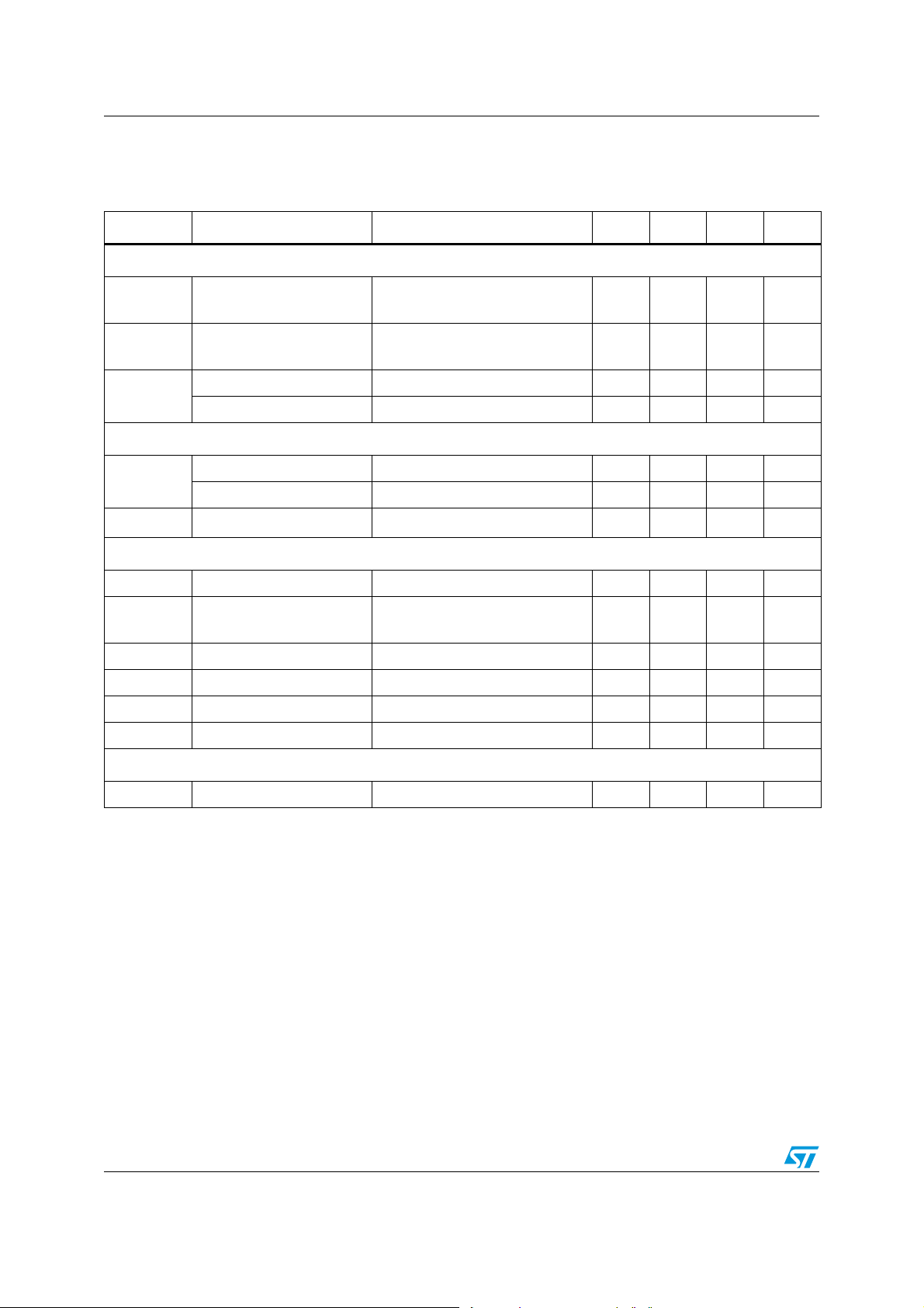
Table 5. Electrical characteristics
(V
= 12V±15%, TJ = 0°C to 70°C unless otherwise specified).
CC
Symbol Parameter Test conditions Min Typ Max Unit
Supply current and power-ON
I
CC
I
BOOT
UVLO
VCC
PWM input
PWM
t
HiZ
Gate drivers
R
HIHS
I
UGATE
R
LOHS
R
HILS
I
LGATE
R
LOLS
Protections
VCC supply current
BOOT supply current
UGATE and LGATE = OPEN
BOOT = 12V
UGATE = OPEN;
PHASE to GND; BOOT = 12V
5mA
2mA
VCC Turn-ON VCC rising 4.1 V
VCC Turn-OFF VCC falling 3.5 V
Input high - V
Input low - V
PWM_IH
PWM_IL
PWM rising 2.3 V
PWM falling 1 V
HiZ Hold-off Time 150 ns
HS Source resistance BOOT - PHASE = 12V; 100mA 2.3 2.8 Ω
HS Source Current
(1)
BOOT - PHASE = 12V;
C
to PHASE = 3.3nF
UGATE
2A
HS Sink Resistance BOOT - PHASE = 12V; 100mA 2 2.5 Ω
LS Source Resistance 100mA 1.3 1.8 Ω
LS Source Current
(1)
C
to GND = 5.6nF 3 A
LGATE
LS Sink Resistance 100mA 1 1.5 Ω
V
PRE_OV
1. Parameter guaranteed by designed, not fully tested in production
Pre-OV threshold PHASE rising 1.8 V
6/16
Page 7
L6741 Device description and operation
5 Device description and operation
L6741 provides high-current driving control for both High-Side and Low-Side N-Channel
MOSFETS connected as Step-Down DC-DC Converter driven by an external PWM signal.
The integrated high-current drivers allow using different types of power MOSFETs (also
multiple MOS to reduce the equivalent RdsON), maintaining fast switching transition.
The driver for the High-Side MOSFET use BOOT pin for supply and PHASE pin for return.
The driver for the Low-Side MOSFET use the VCC pin for supply and PGND pin for return.
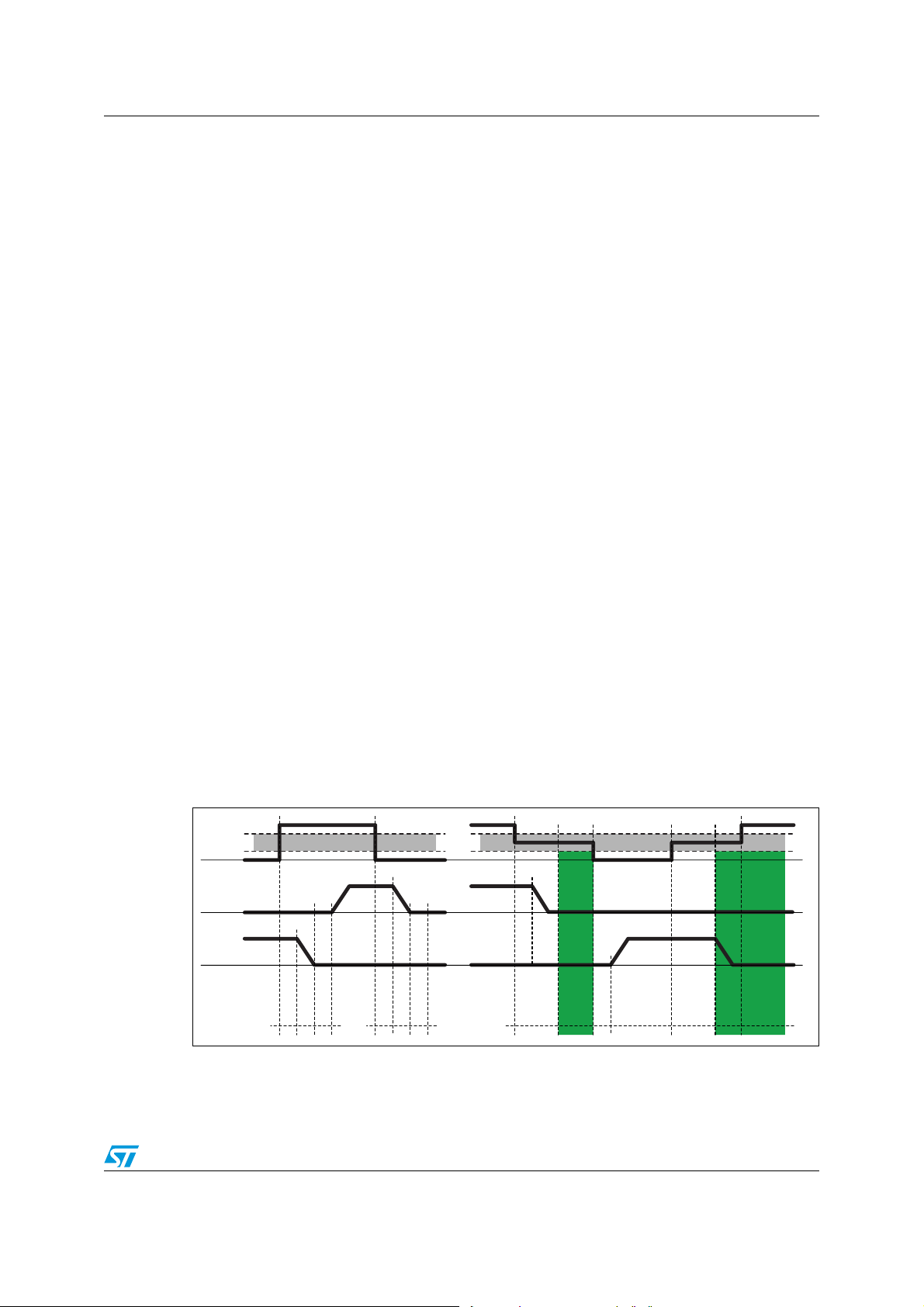
L6741 embodies a anti-shoot-through and adaptive dead-time control to minimize Low-Side
body diode conduction time maintaining good efficiency saving the use of external Schottky
diodes: when the high-side mosfet turns off, the voltage on its source begins to fall; when
the voltage reaches about 2V, the Low-Side MOSFET gate drive voltage is suddenly
applied. When the Low-Side MOSFET turns off, the voltage at LGATE pin is sensed. When
it drops below about 1V, the High-Side MOSFET gate drive voltage is suddenly applied. If
the current flowing in the inductor is negative, the source of highside mosfet will never drop.
To allow the Low-Side MOSFET to turn-on even in this case, a watchdog controller is
enabled: if the source of the High-Side MOSFET doesn't drop, the Low-Side MOSFET is
switched on so allowing the negative current of the inductor to recirculate. This mechanism
allows the system to regulate even if the current is negative.
Before VCC overcome the UVLO threshold, L6741 keeps firmly-OFF both High-Side and
Low-Side MOSFETS then, after the UVLO has crossed, the PWM input keeps the control of
the driver operations. If the PWM input is left floating, the internal resistor divider sets the
HiZ: both MOSFETS are kept in the OFF state until PWM transition.
After UVLO crossing and while in HiZ, the Preliminary-OV protection is activated: if the
voltage senses through the PHASE pin overcome about 2V, the Low-Side MOSFET is
latched ON in order to protect the load from dangerous over-voltage. The Driver status is
reset from a PWM transition.
Driver power supply as well as power conversion input are flexible: every combination of 5V
and 12V can be chosen for High-Side and Low-Side MOSFET voltage drive. Furthermore,
5V, 12V bus or any intermediate bus that allows the conversion can be chosen freely.
Figure 4. Timing diagram
PWM
HS Gate
LS Gate
HiZ Window
prop_H
t
HiZ
HiZ Window
HiZ
prop_L
t
dead_LH
t
prop_H
t
dead_HL
t
t
hold-off
prop_ L
t
t
hold-off
7/16
Page 8

Device description and operation L6741
5.1 High-impedance (HiZ) management
The Driver is able to manage High-Impedance state by keeping all MOSFETs in off state. If
the PWM signal remains in the HiZ window for a time longer than the hold-off time, the
device detects the HiZ condition so turning off all the MOSFETs. The HiZ window is defined
as the PWM voltage range comprised between V
PWM_IL
The device may exit from the HiZ state only after a PWM transition to logic zero (V
V
PWM_IL
).
and V
PWM_IH
.
<
PWM
See Figure 4 for details about HiZ timings.
The implementation of the High-Impedance state allows the controller that will be connected
to the driver to manage High-Impedance state of its output, avoiding to produce negative
undershoot on the regulated voltage during the shut-down stage. Furthermore, different
power management states may be managed such as pre-bias start-up.
5.2 Preliminary OV protection
After VCC has overcome its UVLO threshold and while the PWM signal is in the HiZ window,
L6741 activate the Preliminary-OV protection.
The intent of this protection is to protect the load especially from High-Side MOSFET failures during the system start-up. In fact, VRM, and most in general PWM controllers, have a
12V bus compatible turn-on threshold and results to be non-operative if VCC is below that
turn-on thresholds (that results being in the range of about 10V). In case of an High-Side
mosfet failure, the controller won’t recognize the over voltage until VCC = ~10V (unless
other special features are implemented): but in that case the output voltage is already at the
same voltage (~10V) and the load (CPU in most cases) already burnt.
L6741 by-pass the PWM controller by latching on the Low-Side MOSFET in case the
PHASE pin voltage overcome
HiZ window, the protection is reset and the control of the output voltage is transferred to the
controller connected to the PWM input.
Since the Driver has its own UVLO threshold, a simple way to provide protection to the output in all conditions when the device is OFF consists in supplying the controller through the
5V
bus: 5VSB is always present before any other voltage and, in case of High-Side short,
SB
the Low-Side mosfet is driven with 5V assuring a reliable protection of the load.
Preliminary OV is active after UVLO and while the Driver is in HiZ state and it is disabled
after the first PWM transition. The controller will have to manage its output voltage from that
time on.
5.3 Internal BOOT diode
L6741 embeds a boot diode to supply the High-Side driver saving the use of an external
component. Simply connecting an external capacitor between BOOT and PHASE complete
the High-Side supply connections.
To prevent bootstrap capacitor to extra-charge as a consequence of large negative spikes,
an external series resistance R
BOOT pin.
2V during the HiZ state. When the PWM input exits form the
(in the range of few ohms) may be required in series to
BOOT
8/16
Page 9
L6741 Device description and operation
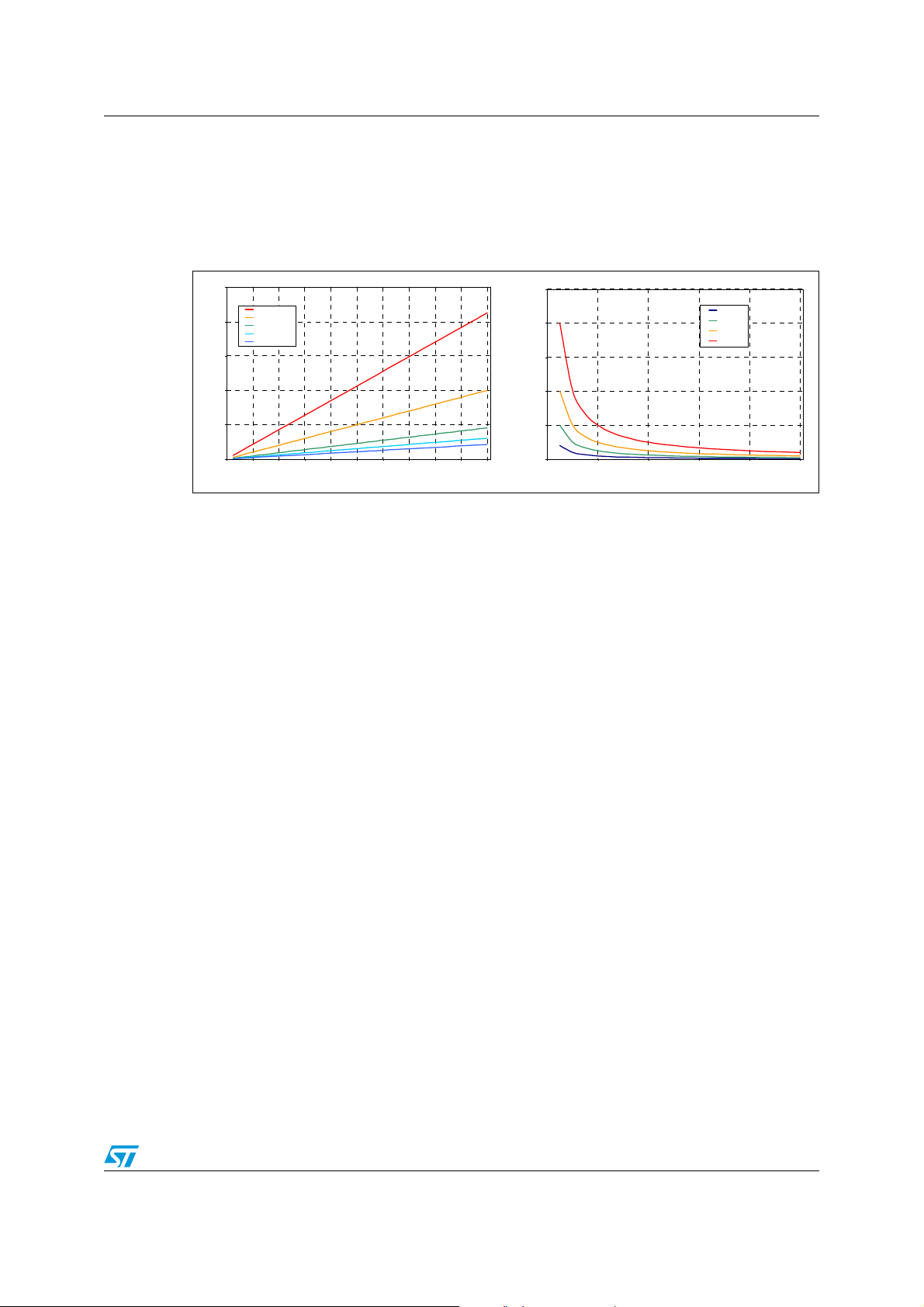
Bootstrap capacitor needs to be designed in order to show a negligible discharge due to the
High-Side MOSFET turn-on. In fact it must give a stable voltage supply to the High-Side
driver during the MOSFET turn-on also minimizing the power dissipated by the embedded
Boot Diode. Figure 5 gives some guidelines on how to select the capacitance value for the
bootstrap according to the desired discharge and depending on the selected mosfet.
Figure 5. Bootstrap capacitance design
2.5
Cboot = 47nF
Cboot = 100nF
2.0
Cboot = 220nF
Cboot = 330nF
Cboot = 470nF
1.5
2500
Qg = 10nC
2000
1500
Qg = 25nC
Qg = 50nC
Qg = 100nC
1.0
BOOT Cap discharge [V]
0.5
0.0
0 102030405060708090100
High-Side MOSFET Gate Charge [nC]
5.4 Gate driver voltage flexibility
L6741 allows the user to freely-select the gate drive voltage in order to optimize the efficiency of the application.
The Low-Side MOSFET driving voltage depends on the voltage applied to VCC and can
range between 5V to 12V buses.
The High-Side MOSFET driving voltage depends on the voltage applied to PVCC (directly
impacting the bootstrap capacitor voltage) and can range between 5V to 12V buses.
5.5 Power dissipation
L6741 embeds high current drivers for both High-Side and Low-Side MOSFETs: it is then
important to consider the power that the device is going to dissipate in driving them in order
to avoid overcoming the maximum junction operative temperature.
1000
Bootstrap Cap [uF]
500
0
0.0 0.2 0.4 0.6 0.8 1.0
Boot Cap Delta Voltage [V]
Two main terms contribute in the device power dissipation: bias power and drivers' power.
● Device Power (P
) depends on the static consumption of the device through the
DC
supply pins and it is simply quantifiable as follow:
P
DCVCCICCVPVCCIPVCC
● Drivers' power is the power needed by the driver to continuously switch ON and OFF
⋅+⋅=
the external MOSFETs; it is a function of the switching frequency and total gate charge
of the selected MOSFETs. It can be quantified considering that the total power P
SW
dissipated to switch the MOSFETs dissipated by three main factors: external gate
resistance (when present), intrinsic MOSFET resistance and intrinsic driver resistance.
9/16
Page 10
Device description and operation L6741
This last term is the important one to be determined to calculate the device power
dissipation.
The total power dissipated to switch the mosfets results:
P
SWFSWQGHS
PVCC⋅ Q
GLS
VCC⋅+()⋅=
When designing an application based on L6741 it is recommended to take into
consideration the effect of external gate resistors on the power dissipated by the driver.
External gate resistors helps the device to dissipate the switching power since the same
power P
will be shared between the internal driver impedance and the external resistor
SW
resulting in a general cooling of the device.
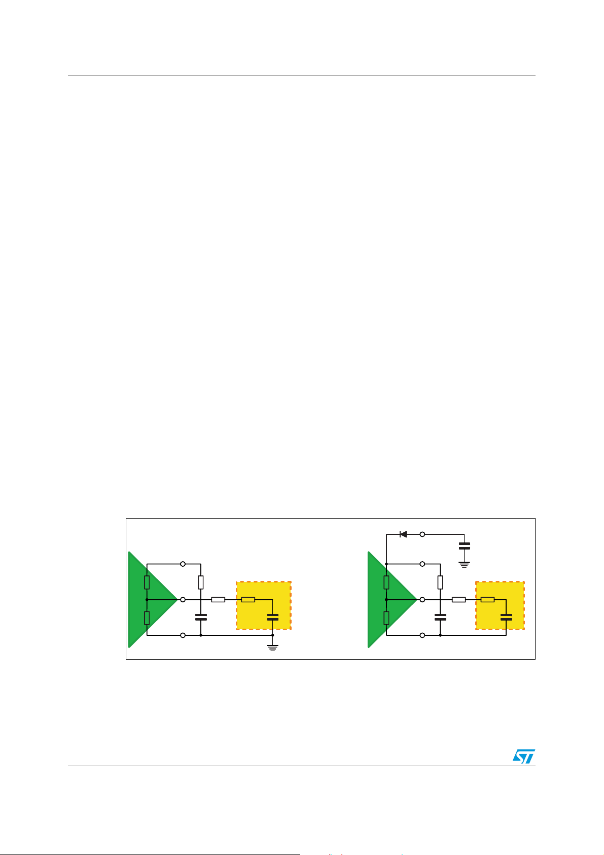
Referring to Figure 6, classical mosfet driver can be represented by a push-pull output stage
with two different mosfets: P-MOSFET to drive the external gate high and N-MOSFET to
drive the external gate low (with their own R
external power mosfet can be represented in this case as a capacitance (C
that stores the gate-charge (Q
G_HS
, Q
G_LS
dsON
: R
hi_HS, Rlo_HS
, R
hi_LS, Rlo_LS
G_HS
). The
, C
G_LS
) required by the external power MOSFET to
)
reach the driving voltage (PVCC for HS and VCC for LS). This capacitance is charged and
discharged at the driver switching frequency F
SW
.
The total power Psw is dissipated among the resistive components distributed along the
driving path. According to the external Gate resistance and the power-MOSFET intrinsic
gate resistance, the driver dissipates only a portion of Psw as follow:
P
P
SW HS–
SW LS–
1
-- -
⋅⋅ ⋅⋅=
2
1
-- -
⋅⋅ ⋅⋅=
C
2
C
GHS
GLS
PVCC2Fsw
VCC2Fsw
⎛⎞
--------------------------------------------------------------- -
⎝⎠
R
⎛⎞
------------------------------------------------------------- -
⎝⎠
R
hiLSRGateLSRiLS
R
hiHS
++
hiHSRGateHSRiHS
R
hiLS
++
--------------------------------------------------------------- -+
R
------------------------------------------------------------- -+
R
loLSRGateLSRiLS
R
loHS
++
loHSRGateHSRiHS
R
loLS
++
The total power dissipated from the driver can then be determined as follow:
PP
DCPSW HS–
++=
P
SW LS–
Figure 6. Equivalent circuit for MOSFET drive.
PVCC
VCC
hiLS
R
loLS
R
LS DRIVER LS MOSFET
LGATE
GND
R
GATELSRILS
C
GLS
hiHS
R
loHS
R
HS DRIVER HS MOSFET
BOOT
HGATE
PHASE
R
GATEHS
R
IHS
C
GHS
10/16
Page 11
L6741 Device description and operation
5.6 Layout guidelines
L6741 provides driving capability to implement high-current step-down DC-DC converters.
The first priority when placing components for these applications has to be reserved to the
power section, minimizing the length of each connection and loop as much as possible. To
minimize noise and voltage spikes (also EMI and losses) power connections must be a part
of a power plane and anyway realized by wide and thick copper traces: loop must be anyway
minimized. The critical components, such as the power MOSFETs, must be close one to the
other. However, some space between the power MOSFET is still required to assure good
thermal cooling and airflow.
Traces between the driver and the MOSFETS should be short and wide to minimize the
inductance of the trace so minimizing ringing in the driving signals. Moreover, VIAs count
needs to be minimized to reduce the related parasitic effect.
The use of multi-layer printed circuit board is recommended.
Small signal components and connections to critical nodes of the application as well as
bypass capacitors for the device supply are also important. Locate the bypass capacitor
(VCC, PVCC and BOOT capacitors) close to the device with the shortest possible loop and
use wide copper traces to minimize parasitic inductance.
Systems that do not use Schottky diodes in parallel to the Low-Side MOSFET might show
big negative spikes on the phase pin. This spike can be limited as well as the positive spike
but has an additional consequence: it causes the bootstrap capacitor to be over-charged.
This extra-charge can cause, in the worst case condition of maximum input voltage and
during particular transients, that boot-to-phase voltage overcomes the abs.max.ratings also
causing device failures. It is then suggested in this cases to limit this extra-charge by adding
a small resistor R
the limitation of the spike present on the BOOT pin.
in series to the boot capacitor. The use of R
BOOT
also contributes in
BOOT
For heat dissipation, place copper area under the IC. This copper area may be connected
with internal copper layers through several VIAs to improve the thermal conductivity. The
combination of copper pad, copper plane and VIAs under the driver allows the device to
reach its best thermal performances.
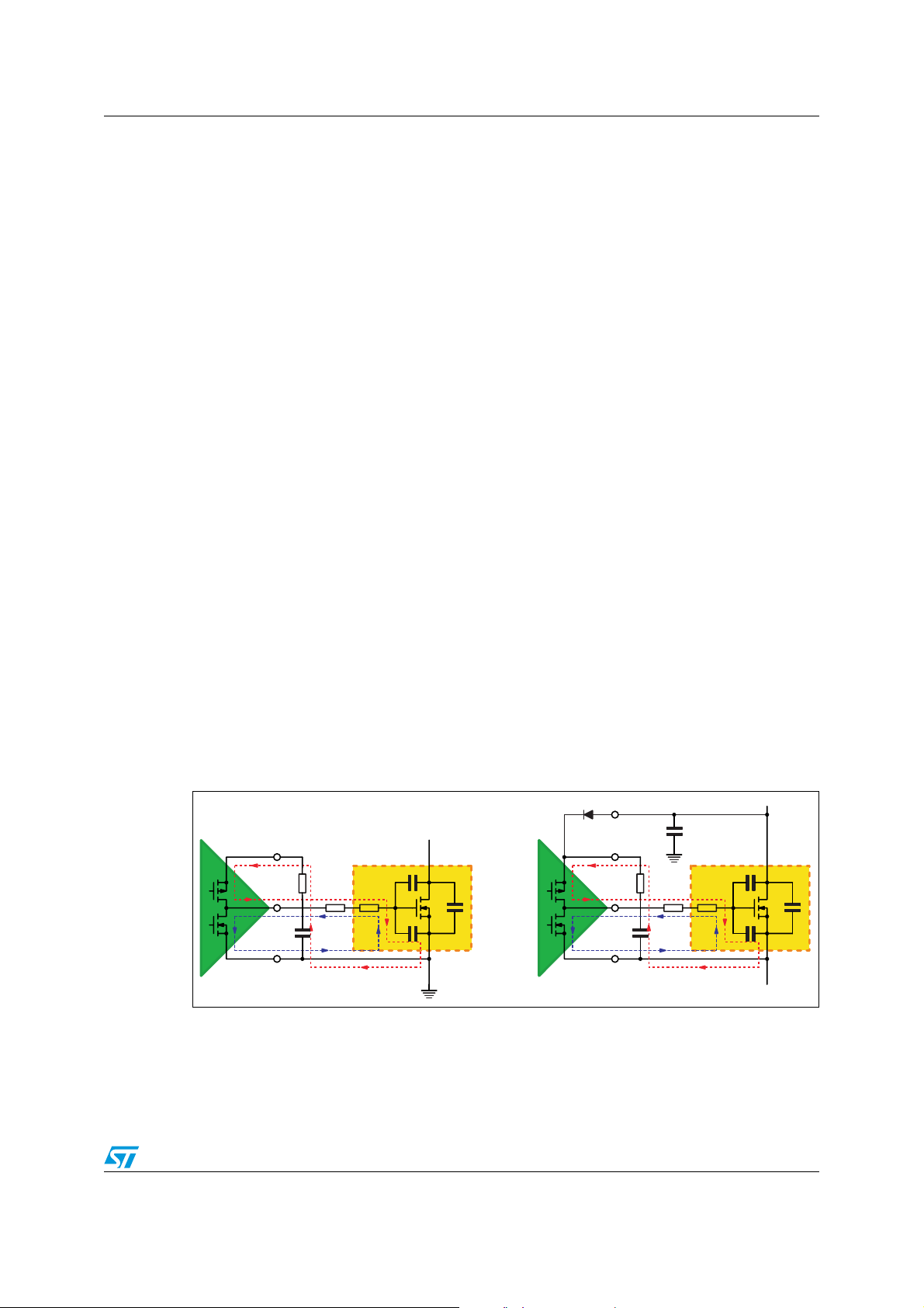
Figure 7. Driver turn-on and turn-off paths
VCC
VCC
C
R
BOOT
R
GATERINT
LGATE
C
BOOT
LS DRIVER LS MOSFET
GND
GD
C
GS
C
DS
HS DRIVER HS MOSFET
BOOT
R
BOOT
HGATE
C
BOOT
PHASE
R
GATERINT
C
GD
C
GS
C
DS
11/16
Page 12
Device description and operation L6741
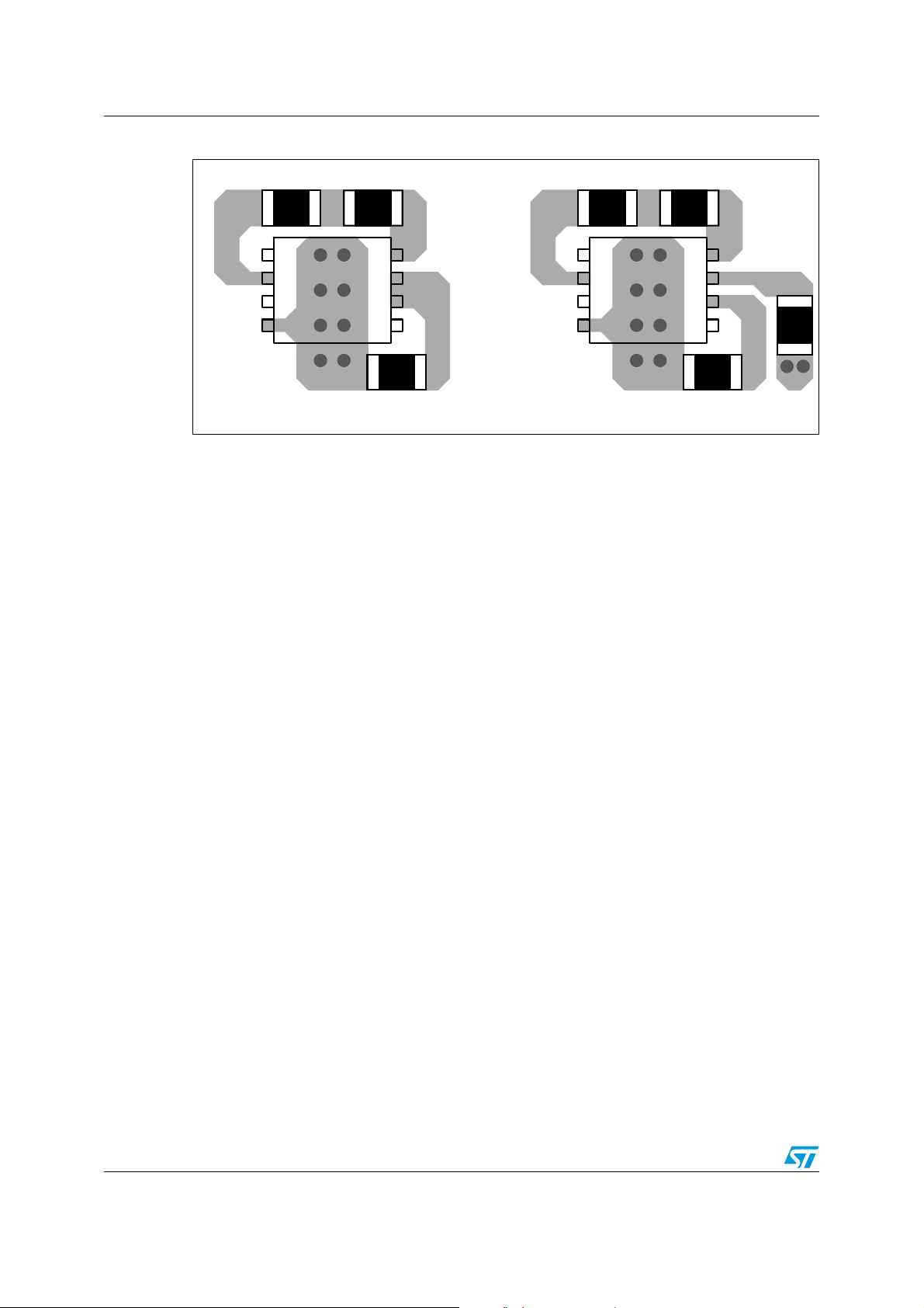
Figure 8. External components placement example.
Rboot Cboot Rboot Cboot
UGATE
BOOT
PWM
GND
1
2
3
L6741
4
8
7
6
5
PHASE
PVCC
VCC
LGATE
UGATE
BOOT
PWM
GND
1
2
3
L6741
4
8
7
6
5
SINGLE SUPPLY (VCC = PVCC) DUAL SUPPLY (VCC <> PVCC)
PHASE
PVCC
VCC
LGATE
12/16
Page 13

L6741 Package mechanical data
6 Package mechanical data
In order to meet environmental requirements, ST offers these devices in ECOPACK®
packages. These packages have a Lead-free second level interconnect . The category of
second level interconnect is marked on the package and on the inner box label, in
compliance with JEDEC Standard JESD97. The maximum ratings related to soldering
conditions are also marked on the inner box label. ECOPACK is an ST trademark.
ECOPACK specifications are available at: www.st.com
13/16
Page 14
Package mechanical data L6741
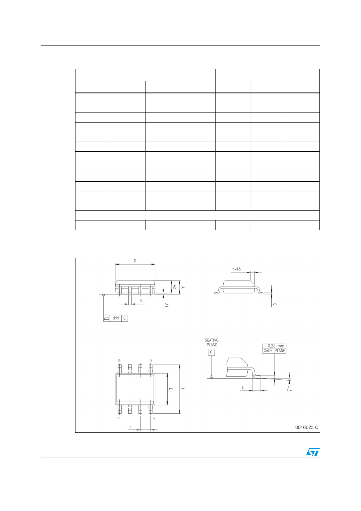
Table 6. SO-8 mechanical data
Dim.
Min Typ Max Min Typ Max
A 1.35 1.75 0.053 0.069
A1 0.10 0.25 0.004 0.010
A2 1.10 1.65 0.043 0.065
B 0.33 0.51 0.013 0.020
C 0.19 0.25 0.007 0.010
(1)
D
4.80 5.00 0.189 0.197
E 3.80 4.00 0.15 0.157
e 1.27 0.050
H 5.80 6.20 0.228 0.244
h 0.25 0.50 0.010 0.020
L 0.40 1.27 0.016 0.050
k 0° (min.), 8° (max.)
ddd 0.10 0.004
1. Dimensions D does not include mold flash, protru-sions or gate burrs. Mold flash, potrusions or gate burrs
shall not exceed 0.15mm (.006inch) in total (both side).
mm. inch
Figure 9. Package dimensions
14/16
Page 15

L6741 Revision history
7 Revision history
Table 7. Document revision history
Date Revision Changes
20-Aug-2007 1 Initial release.
15/16
Page 16

L6741
Please Read Carefully:
Information in this document is provided solely in connection with ST products. STMicroelectronics NV and its subsidiaries (“ST”) reserve the
right to make changes, corrections, modifications or improvements, to this document, and the products and services described herein at any
time, without notice.
All ST products are sold pursuant to ST’s terms and conditions of sale.
Purchasers are solely responsible for the choice, selection and use of the ST products and services described herein, and ST assumes no
liability whatsoever relating to the choice, selection or use of the ST products and services described herein.
No license, express or implied, by estoppel or otherwise, to any intellectual property rights is granted under this document. If any part of this
document refers to any third party products or services it shall not be deemed a license grant by ST for the use of such third party products
or services, or any intellectual property contained therein or considered as a warranty covering the use in any manner whatsoever of such
third party products or services or any intellectual property contained therein.
UNLESS OTHERWISE SET FORTH IN ST’S TERMS AND CONDITIONS OF SALE ST DISCLAIMS ANY EXPRESS OR IMPLIED
WARRANTY WITH RESPECT TO THE USE AND/OR SALE OF ST PRODUCTS INCLUDING WITHOUT LIMITATION IMPLIED
WARRANTIES OF MERCHANTABILITY, FITNESS FOR A PARTICULAR PURPOSE (AND THEIR EQUIVALENTS UNDER THE LAWS
OF ANY JURISDICTION), OR INFRINGEMENT OF ANY PATENT, COPYRIGHT OR OTHER INTELLECTUAL PROPERTY RIGHT.
UNLESS EXPRESSLY APPROVED IN WRITING BY AN AUTHORIZED ST REPRESENTATIVE, ST PRODUCTS ARE NOT
RECOMMENDED, AUTHORIZED OR WARRANTED FOR USE IN MILITARY, AIR CRAFT, SPACE, LIFE SAVING, OR LIFE SUSTAINING
APPLICATIONS, NOR IN PRODUCTS OR SYSTEMS WHERE FAILURE OR MALFUNCTION MAY RESULT IN PERSONAL INJURY,
DEATH, OR SEVERE PROPERTY OR ENVIRONMENTAL DAMAGE. ST PRODUCTS WHICH ARE NOT SPECIFIED AS "AUTOMOTIVE
GRADE" MAY ONLY BE USED IN AUTOMOTIVE APPLICATIONS AT USER’S OWN RISK.
Resale of ST products with provisions different from the statements and/or technical features set forth in this document shall immediately void
any warranty granted by ST for the ST product or service described herein and shall not create or extend in any manner whatsoever, any
liability of ST.
ST and the ST logo are trademarks or registered trademarks of ST in various countries.
Information in this document supersedes and replaces all information previously supplied.
The ST logo is a registered trademark of STMicroelectronics. All other names are the property of their respective owners.
© 2007 STMicroelectronics - All rights reserved
STMicroelectronics group of companies
Australia - Belgium - Brazil - Canada - China - Czech Republic - Finland - France - Germany - Hong Kong - India - Israel - Italy - Japan -
Malaysia - Malta - Morocco - Singapore - Spain - Sweden - Switzerland - United Kingdom - United States of America
www.st.com
16/16
 Loading...