

Page 1
Silicon Piezoresistive
Absolute Pressure Sensor
Preliminary Data
Features
• Low pressure and temperature hysteresis
• Fast response
• High sensitivity and linearity
• Fatigue free monocrystaline silicon diaphragm
giving high load cycle stability
• High long term stability
• Built in silicon temperature sensor
• Provided for further fabrication, protection cap
KPY 62-AK
KPY 69-AK
Similar to TO-39-2
Type and
Symbol Pressure Range Unit Ordering Code
Marking
KPY 62 AK
P
… P
0
0 … 0.6 bar Q62705-K275
N
KPY 63 AK 0 … 1.6 Q62705-K276
KPY 64 AK 0 … 4 Q62705-K277
KPY 65 AK
0
… 10 Q62705-K278
KPY 66 AK 0 … 25 Q62705-K279
KPY 67 AK 0 … 60 Q62705-K280
KPY 68 AK 0 … 160 Q62705-K281
KPY 69 AK 0 … 400 Q62705-K282
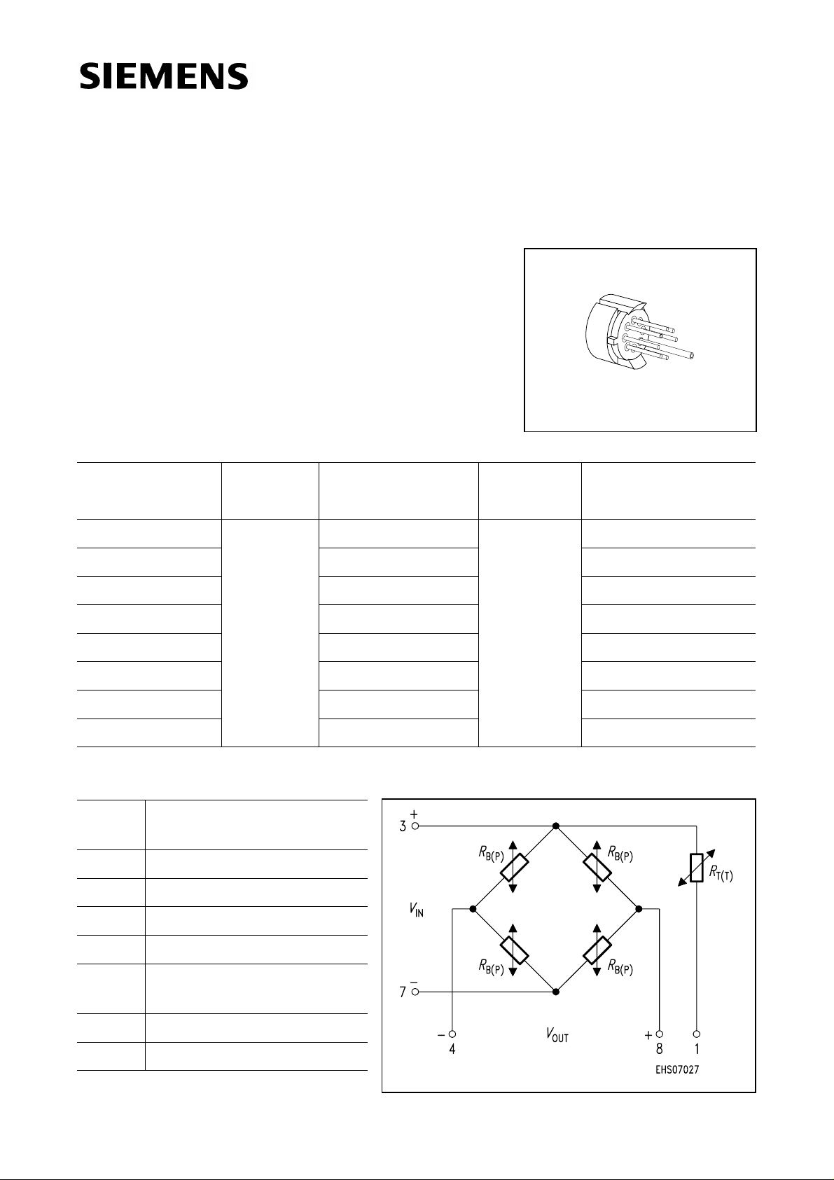
Pin Configuration
1 Temperature sensor
(typ.
R
= 2 kΩ)
25
2 Not connected
3+
4 −
V
; Temperature sensor
IN
V
OUT
5 Capillary tube
6 Shielding, to be connected
to +
V
IN
7 − V
8+V
Semiconductor Group 1 1998-05-08
IN
OUT
Page 2
KPY 62-AK
KPY 69-AK
Absolute Maximum Ratings
Parameter Symbol Limit Values Unit
Pressure overload
Operating temperature range
Storage temperature range
Supply voltage
KPY 62 AK
KPY 63 AK
KPY 64 AK
KPY 65 AK
KPY 66 AK
KPY 67 AK
KPY 68 AK
KPY 69 AK
P
T
T
V
MAX
A
stg
IN
4
8
12
20
50
70
200
500
− 40 …+ 125 ˚C
− 50 …+ 125 ˚C
12 V
bar
Electrical Characteristics
at
T
= 25 ˚C and VIN = 5 V, unless otherwise specified.
A
Parameter Symbol Limit Values Unit
min. typ. max.
Bridge resistance
Sensitivity
Output voltage
KPY 62 AK
KPY 63 AK
KPY 64 AK
KPY 65 AK
KPY 66 AK
KPY 67 AK
KPY 68 AK
KPY 69 AK
KPY 62 AK
KPY 63 AK
KPY 64 AK
KPY 65 AK
KPY 66 AK
KPY 67 AK
KPY 68 AK
KPY 69 AK
R
s
V
B
fin
4 − 8kΩ
mV/
23.3
11.3
6.5
3.6
1.1
0.63
0.38
0.16
43.0
20.0
11.0
5.2
2.1
1.0
0.53
0.22
73.3
30.0
15.5
8.0
3.0
1.4
0.66
0.27
Vbar
mV
70
90
130
180
150
190
310
330
130
160
220
260
260
300
420
440
220
240
310
400
370
410
530
550
Semiconductor Group 2 1998-05-08
Page 3

KPY 62-AK
KPY 69-AK
Electrical Characteristics (cont’d)
at
T
= 25 ˚C and VIN = 5 V, unless otherwise specified.
A
Parameter Symbol Limit Values Unit
min. typ. max.
Offset voltage
P = P
0
Linearity error (Best fit straight line)
P
= P0… P
0
N
KPY 62 … 65 AK
KPY 66 … 69 AK
Pressure hysteresis
P
= P0,P2 = PN,P3 = P0KPY 62 … 69 AK
1
V
F
P
0
mV
− 25 −+ 25
L
−
−
H
± 0.3
± 0.3
± 0.5
−
% V
V
%
−± 0.1 −
Electrical Characteristics
at
T
= 25 ˚C, T2 = 125 ˚C, T3 = 25 ˚C and VIN = 5 V, unless otherwise specified.
1
Parameter Symbol Limit Values Unit
min. typ. max.
Temperature coefficient of
V
fin
TC
Vfin
%/K
KPY 62 … 69 AK − 0.22 − 0.18 − 0.15
Temperature coefficient of
V
0
TC
V0
%/K
fin
fin
KPY 62 AK
KPY 63 AK
KPY 64 AK
KPY 65 AK
KPY 66 AK
KPY 67 AK
KPY 68 AK
KPY 69 AK
Temperature coefficient of
KPY 62 … 69 AK −+ 0.23 −
Temperature hysteresis of
KPY 62 …66 AK
KPY 67 …69 AK
R
V
B
0
; V
fin
TC
TH
RB
− 0.04
− 0.04
− 0.02
− 0.02
− 0.02
− 0.01
− 0.01
− 0.01
−
−
−
−
−
−
−
−
−
−
± 0.2
− 0.1
+ 0.04
+ 0.04
+ 0.02
+ 0.02
+ 0.02
+ 0.01
+ 0.01
+ 0.01
−
−
%/K
% v. V
fin
Semiconductor Group 3 1998-05-08
Page 4

Package Outline
Similar to TO-39-2
Basic Component
±0.1
12
±0.5
8
View on Chip
9.3
-0.2
KPY 62-AK
KPY 69-AK
±0.1
ø1.05
±0.1
7.6
-0.1
ø0.65
2.6 max
Bond Wire
Loop
Component Delivery Form
±0.6
18.2
±0.6
14.2
-0.5
ø11.5
±0.6
5
6.2
±0.6
8
±0.6
3.59
6
8
5.08
5
1
4
37
2
3.59
5.08
45˚
GMT05959
Weight approx. 1.5 g
Dimensions in mm
Exterior Packaging
I.e. tubes, trays, boxes are shown in our Data Book “Package Information”.
Semiconductor Group 4 1998-05-08
 Loading...