

Page 1

MAGNETIC ANGLE SENSOR
KMT32B
Preliminary
HLP Confidential
Preliminary Data Sheet
KMT32B
Axel Bartos
HL PLANARTECHNIK GmbH • Hauert 13 • 44227 Dortmund • Germany • www.hlplanar.de
service@hlplanar.de • phone: +49-(0)231-97400 • fax: +49-(0)231-974020
KMT32B_PreliminaryDataSheet (2004-04-13).doc Last update 13.04.04
Page 2
Vcc2
Br.2
Br.1
Vcc
MAGNETIC ANGLE SENSOR
KMT32B
Preliminary
HLP Confidential
LEGAL DISCLAIMER
This product is not designed for use in life support appliances, devices or systems where malfunction of this product can
reasonably be expected to result in personal injury. HL Planartechnik GmbH customers using or selling this product for use in such
applications do so at their own risk and agree to fully indemnify HL Planartechnik GmbH for any damages resulting from such
improper use or sale.
This data sheet contains target specifications for product development which my be subject to changes without notice.
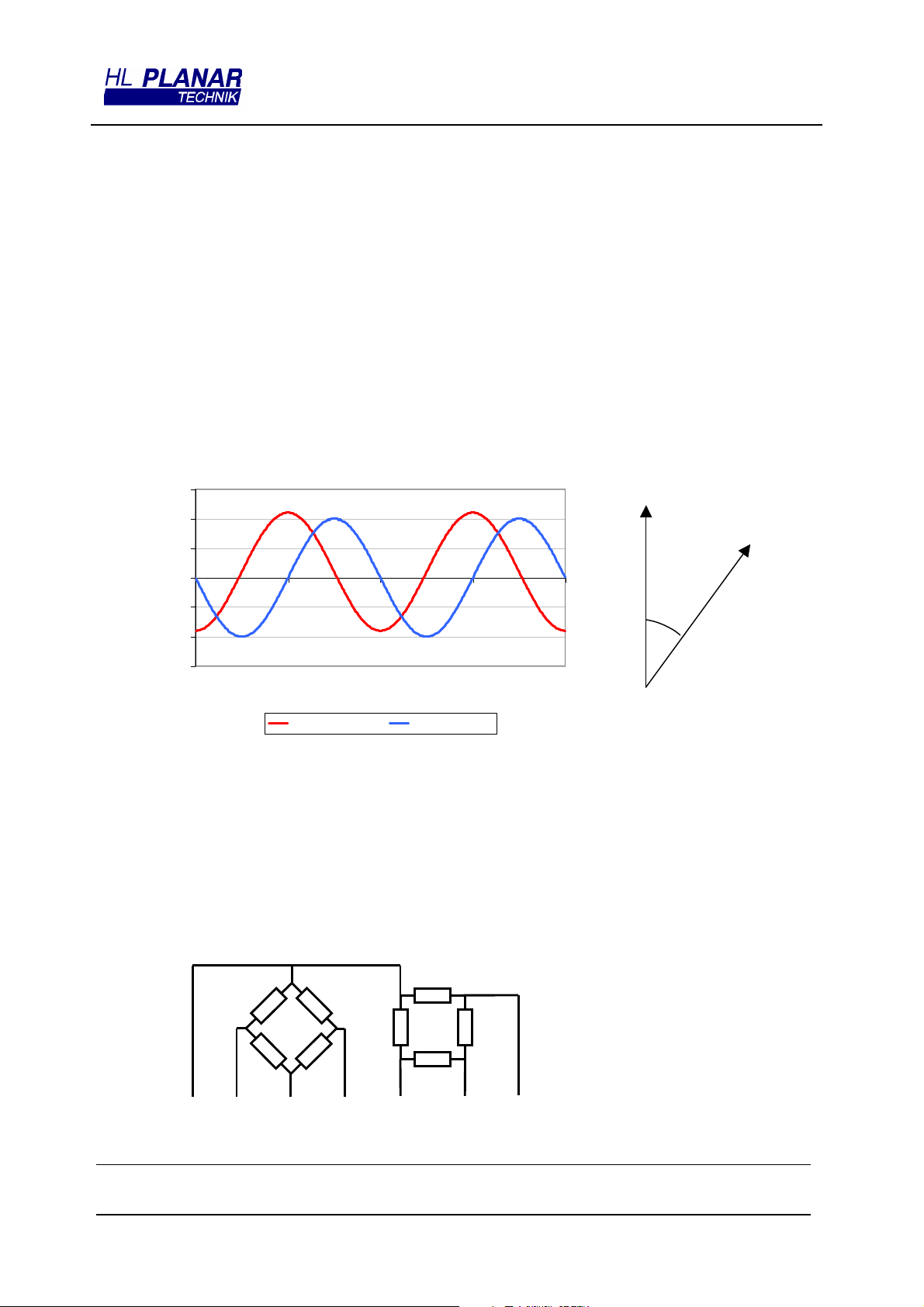
GENERAL DESCRIPTION
The KMT32B is a magnetic field sensor based on the anisotropic magnetoresistance effect. The sensor
contains two parallel supplied Wheatstone bridges, which enclose a sensitive angle of 45 degrees.
A rotating magnetic field in the surface parallel to the chip (x-y plane) will deliver two independent
sinusoidal output signals, one following a cos(2α) and the second following a sin(2α) function, α being
the angle between sensor and field direction (see figure 2).
15
10
5
y
0
0 90 180 270 360
-5
Uo/Ucc [mV/V]
-10
-15
[deg]
αααα
bridge 1 (cosine) bridge 2 (sine)
α
field direction
Fig. 2
Figure 1: Characteristic curves for KMT32B
The KMT32B is suited for high precision angle measurement applications under low field conditions
(regular 25 kA/m, with reduced accuracy applicable down to 8 kA/m; beware of earth’s magnetic field !).
CIRCUIT DIAGRAM
Fig. 3
-Vo1
GND
+Vo1
1
-Vo2
-Vo2
HL PLANARTECHNIK GmbH • Hauert 13 • 44227 Dortmund • Germany • www.hlplanar.de
service@hlplanar.de • phone: +49-(0)231-97400 • fax: +49-(0)231-974020
KMT32B_PreliminaryDataSheet (2004-04-13).doc Last update 13.04.04
Page 3

MAGNETIC ANGLE SENSOR
KMT32B
CHARACTERISTIC VALUES (PRELIMINARY)
S
YMBOL
cc,max
tot
U
NIT
MIN TYP MAX C
V 10
mA 4
mW TBD @T= TBD °C
°C
°C
-40 +150
-25 +150
P
ARAMETER
A. Operating Limits
max. supply voltage
max. current (single bridge)
power dissipation
operating temperature
storage temperature
V
I
cc,max
P
Top
Tst
B. Sensor Specifications (T=25 °C)
Preliminary
HLP Confidential
ONDITION
Supply voltage
Resistance (single bridge)
Signal amplitude
Offset voltage
angular inaccuracy
angular hysteresis
Vcc
Rb
∆
V/Vcc
V
off
∆α
∆α
H
V 5 8.5
Ω
mV/V 17 20 Condition A, B
mV/V -1 0 +1 Condition A, B
deg 0.05 0.2 Condition A, B
deg 0.1 Condition A, B
2400 3000 3600
C. Sensor Specifications
TC of amplitude
TC of resistance
TC of offset
Limiting values given are in accordance with the Absolute Maximum Rating System (IEC 134). Stress above one or more of the
limiting values may cause permanent damage to the device. These are stress ratings only and operation of the device at these or
at any other conditions above those given in the Characteristics sections of this specification is not implied. Exposure to limiting
values for extended periods may affect device reliability.
TCSV
TCBR
TCVoff
%/K -0.36 -0.32 -0.28 Condition A, C
%/K +0.27 +0.32 +0.37 Condition A, C
µV/V/K -4 0 +4 Condition A, C
HL PLANARTECHNIK GmbH • Hauert 13 • 44227 Dortmund • Germany • www.hlplanar.de
service@hlplanar.de • phone: +49-(0)231-97400 • fax: +49-(0)231-974020
KMT32B_PreliminaryDataSheet (2004-04-13).doc Last update 13.04.04
Page 4

MAGNETIC ANGLE SENSOR
KMT32B
MEASUREMENT CONDITIONS
S
YMBOL
P
ARAMETER
A. Set Up Conditions
U
NIT
C
ONDITION
Preliminary
HLP Confidential
ambient temperature T °C
supply voltage
applied magnetic field H kA/m H=25 kA/m
Vcc
V Vcc=5 V
B. Sensor Specifications (T=25 °C, 360° turn , H=25 kA/m , Vo
signal amplitude
signal offset
angular hysteresis
angular inaccuracy
∆
V/V
Voff
∆α
∆α
H
mV/V
mV/V Voff=Vo
deg
deg
T = 23±5 °C (unless otherwise noted)
>0, Vo
max
∆V/V=Vo
∆α
H = MAX|
max. angular difference between left and right turn
∆α=
MAX|
max. angular difference between actual value
measured angle; offset voltage error contributions not
included
max
max
α
- Vo
+ Vo
α
left turn
-α|
0
min
min
-
α
right turn
|
C. Sensor Specifications (T=-25°C, +125°C)
ambient temperatures T °C T1=-25 °C, T0=+25 °C, T2=+125 °C
TC of amplitude
TCSV
%/K
∆
V
1
=
TCV
−
V
⋅
)(
TT
12
−
T
∆
V
T
V
∆
min
V
1
V
)(
<0)
T
α
and
0
)()(
12
%100
⋅
TC of resistance
TC of offset
TCBR
TCVoff
HL PLANARTECHNIK GmbH • Hauert 13 • 44227 Dortmund • Germany • www.hlplanar.de
service@hlplanar.de • phone: +49-(0)231-97400 • fax: +49-(0)231-974020
%/K
µV/(VK)
=
TCR
TCVoff
1
⋅
)(
−
TT
12
=
−
TR
−
)(
TT
−
12
)()(
TRTR
12
⋅
)(
1
)()(
TVoffTVoff
12
%100
KMT32B_PreliminaryDataSheet (2004-04-13).doc Last update 13.04.04
Page 5

MAGNETIC ANGLE SENSOR
KMT32B
Preliminary
HLP Confidential
PIN LAYOUT KMT32B
LAYOUT PIN SYMBOL DESCRIPTION
1 -Vo1 negative output bridge 1 (sin)
2 -Vo2 negative output bridge 2 (cos)
3 Vcc2 positive supply voltage bridge 2
4 Vcc1 positive supply voltage bridge 1
5 +Vo1 positive output bridge 1 (sin)
6 +Vo2 positive output bridge 2 (cos)
7 GND common ground
8 GND common ground
PAD LAYOUT KMT32B CHIP
LAYOUT PAD SYMBOL DESCRIPTION
ORDERING CODE
KMT32B chip TBD
1 -Vo1 negative output bridge 1 (sin)
2 -Vo2 negative output bridge 2 (cos)
3 Vcc2 positive supply voltage bridge 2
4 Vcc1 positive supply voltage bridge 1
5 +Vo1 positive output bridge 1 (sin)
6 +Vo2 positive output bridge 2 (cos)
7 GND common ground
8 GND common ground
KMT32B SM8 TBD
HL PLANARTECHNIK GmbH • Hauert 13 • 44227 Dortmund • Germany • www.hlplanar.de
service@hlplanar.de • phone: +49-(0)231-97400 • fax: +49-(0)231-974020
KMT32B_PreliminaryDataSheet (2004-04-13).doc Last update 13.04.04
 Loading...