

Page 1

DISCRETE SEMICONDUCTORS
DATA SH EET
KMI15/1
Integrated rotational speed sensor
Preliminary specification
File under Discrete Semiconductors, SC17
1996 Dec 05
Page 2

Philips Semiconductors Preliminary specification
Integrated rotational speed sensor KMI15/1
FEATURES
• Digital current output signal
• Zero speed capability
• Wide air gap
• Wide temperature range
• Insensitive to vibration
• EMC resistant.
DESCRIPTION
The KMI15/1 sensor detects rotational speed of ferrous
gear wheels and reference marks
(1)
.
The sensor consists of a magnetoresistive sensor
element, a signal conditioning integrated circuit in bipolar
technology and a magnetized ferrite magnet.
The frequency of the digital current output signal is
proportional to the rotational speed of a gear wheel.
CAUTION
Do not press two or more products together against their
magnetic forces.
PINNING
PIN DESCRIPTION
1V
CC
2V−
handbook, halfpage
12
MBH781
(1) The sensor contains a customized integrated circuit. Usage in
hydraulic brake systems and in systems with active brake
control is forbidden.
Fig.1 Simplified outline; (SOT453B).
QUICK REFERENCE DATA
SYMBOL PARAMETER MIN. TYP. MAX. UNIT
V
CC
I
CC (low)
I
CC (high)
DC supply voltage − 12 − V
current output signal low − 7 − mA
current output signal high − 14 − mA
d sensing distance 0 to 2.5 0 to 2.9 − mm
f
t
T
amb
operating tooth frequency 0 − 25000 Hz
ambient operating temperature −40 − +85 °C
1996 Dec 05 2
Page 3

Philips Semiconductors Preliminary specification
Integrated rotational speed sensor KMI15/1
LIMITING VALUES
In accordance with Absolute Maximum Rating System (IEC 134).
SYMBOL PARAMETER CONDITIONS MIN. MAX. UNIT
V
CC
T
stg
T
amb
T
sld
Note
1. With R
(see Fig.7).
CHARACTERISTICS
=25°C; VCC= 12 V; d = 2.1 mm; ft= 2 kHz; test circuit: see Fig.7; RL=115Ω; sensor positioning: see Fig.15;
T
amb
gear wheel: module 2 mm; material 1.0715; unless otherwise specified.
DC supply voltage T
= −40 to +85 °C; RL=115Ω− 16 V
amb
storage temperature −40 +150 °C
ambient operating temperature −40 +85 °C
soldering temperature t ≤ 10 s − 260 °C
output short-circuit duration to GND continuous; note 1
= 115 Ω the device is continuously protected against wrong polarity of DC supply voltage (VCC) to GND
L
SYMBOL PARAMETER CONDITIONS MIN. TYP. MAX. UNIT
I
CC (low)
I
CC (high)
t
r
t
f
t
d
current output signal low see Figs 6 and 8 5.6 7.0 8.4 mA
current output signal high see Figs 6 and 8 11.2 14.0 16.8 mA
output signal rise time CL= 100 pF; see Fig.9; 10 to 90% value − 0.5 −µs
output signal fall time CL= 100 pF; see Fig.9; 10 to 90% value − 0.7 −µs
switching delay time between stimulation pulse (generated
− 1 −µs
by a coil) and output signal
f
t
operating tooth frequency for both rotation directions 0 − 25000 Hz
d sensing distance see Fig.15 and note 1 0 to 2.5 0 to 2.9 − mm
δ duty cycle see Fig.6 30 50 70 %
Note
1. High rotational speeds of wheels reduce the sensing distance due to eddy current effects (see Fig.17).
1996 Dec 05 3
Page 4
Philips Semiconductors Preliminary specification
Integrated rotational speed sensor KMI15/1
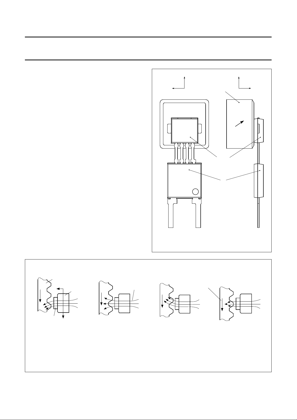
FUNCTIONAL DESCRIPTION
The KMI15/1 sensor is sensitive to the motion of ferrous
gear wheels or reference marks. The functional principle is
shown in Fig.3. Due to the effect of flux bending, the
different directions of magnetic field lines in the
magnetoresistive sensor element will cause an electrical
signal. Because of the chosen sensor orientation and the
direction of ferrite magnetization, the KMI15/1 is sensitive
to movement in the ‘y’ direction in front of the sensor only
(see Fig.2).
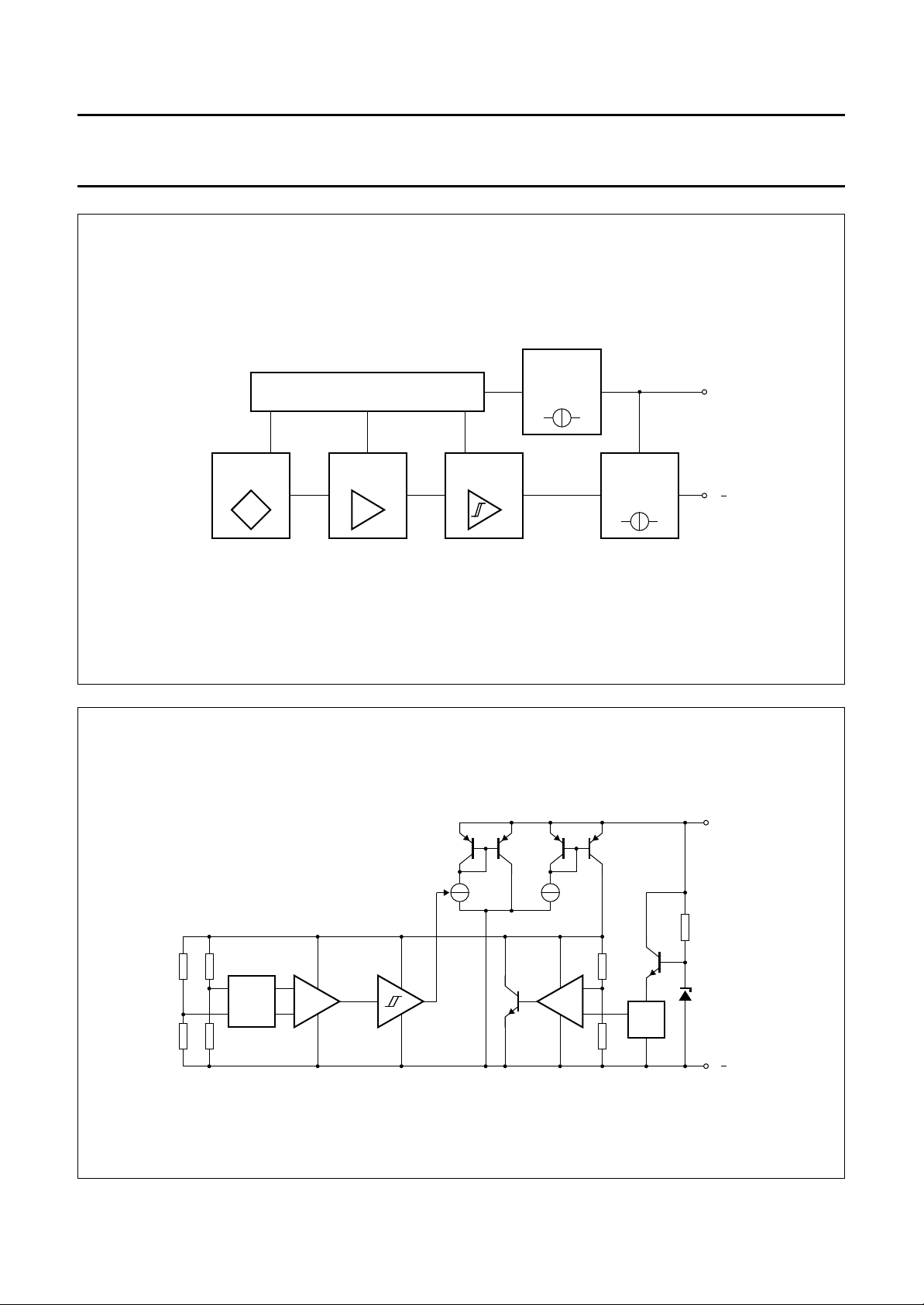
The magnetoresistive sensor element signal is amplified,
temperature compensated and passed to a Schmitt trigger
in the conditioning integrated circuit (Figs 4 and 5).
The digital output signal level (see Fig.6) is independent of
the sensing distance within the measuring range (Fig.14).
A (2-wire) output current enables safe transfer of the
sensor signal to the detecting circuit (see Fig.7).
The integrated circuit housing is separated from the
sensor element housing to optimize the sensor behaviour
at high temperatures.
handbook, halfpage
y
xx
magnet with
direction of
magnetization
sensor
IC
z
handbook, full pagewidth
gear wheel
z
sensor
Fig.2 Component detail of the KMI15/1.
magnetic
magnet
y
(a) (b) (c)
field lines
Fig.3 Functional principle.
direction
of
motion
MBH778
MRA957
(d)
1996 Dec 05 4
Page 5
Philips Semiconductors Preliminary specification
Integrated rotational speed sensor KMI15/1
handbook, full pagewidth
VOLTAGE CONTROL
AMPLIFIERSENSOR
Fig.4 Block diagram.
SCHMITT
TRIGGER
CONSTANT
CURRENT
SOURCE
SWITCHABLE
CURRENT
SOURCE
V
MRA958
CC
V
handbook, full pagewidth
sensor
EMC
FILTER
pre-
amplifier
switchable
current source
Schmitt-
trigger
Fig.5 Simplified circuit diagram.
1996 Dec 05 5
power supply
constant
current source
V
ref
GAP
MRA959
V
CC
V
Page 6

Philips Semiconductors Preliminary specification
Integrated rotational speed sensor KMI15/1
handbook, halfpage
I
δ
CC
14 mA
7 mA
t
p
--- T
100%×=
T
t
p
Fig.6 Output signal as a function of time.
APPLICATION INFORMATION
16
handbook, halfpage
I
CC
(mA)
14
12
10
8
6
4
50 0 50 100 150 200
I
CC(high)
I
CC(low)
VCC = 20 V
VCC = 20 V
MRA967
VCC = 12 V
VCC = 8 V
VCC = 12 V
VCC = 8 V
T
amb
MRA960
(oC)
V
C
GND
CC
V
L
SENSOR
I
CC
R
L
MRA961
t
Fig.7 Test and application circuit.
T
amb
MRA968
t
f
o
( C)
t
1
handbook, halfpage
t
µ
(s)
0.8
0.6
0.4
0.2
0
50
t
f
t
r
I
CC
t
r
0 50 100 150 200
Fig.8 Output current levels as functions of
ambient temperature.
1996 Dec 05 6
VCC= 12V; CL= 100pF; RL= 115Ω.
Fig.9 Output current switching times as functions
of ambient temperature.
Page 7

Philips Semiconductors Preliminary specification
Integrated rotational speed sensor KMI15/1
Mounting conditions
The recommended sensor position in front of a gear wheel
is shown in Fig.15. The distance ‘d’ is measured between
the sensor front and the tip of a gear wheel tooth.
The KMI15/1 senses ferrous indicators like gear wheels in
the ± y direction only (no rotational symmetry of the
sensor); see Fig.2. The effect of incorrect mounting
positions on sensing distance is shown in Figs 11, 12 and
13. The symmetrical reference axis of the sensor
corresponds to the axis of the ferrite magnet.
Environmental conditions
Due to eddy current effects the sensing distance depends
on the tooth frequency (Fig.17). The influence of gear
wheel module on the sensing distance is shown in Fig.16.
pitch
handbook, halfpage
Gear Wheel Dimensions
SYMBOL DESCRIPTION UNIT
German DIN
z number of teeth
d diameter mm
m module m = d/z mm
p pitch p = π×mmm
ASA; note1
PD pitch diameter (d in inch) inch
DP diametric pitch DP = z/PD inch
−1
CP circular pitch CP = π/DP inch
Note
1. For conversion from ASA to DIN: m = 25.4 mm/DP;
p = 25.4 mm × CP.
handbook, halfpage
4
d
(mm)
3
MRA998
pitch
diameter
module
pitch =module ×π
pitch diameter
=
-----------------------------------------number ofteeth
MRA964
Fig.10 Gear wheel dimensions.
1996 Dec 05 7
2
d
1
0
01234
VCC= 12V; ft= 2kHz; module = 2 mm; pitch diameter = 100 mm.
y
y (mm)
Fig.11 Sensing distance as a function of positional
tolerance in the y-axis.
Page 8

Philips Semiconductors Preliminary specification
Integrated rotational speed sensor KMI15/1
handbook, halfpage
4
d
(mm)
3
2
d
1
0
01
VCC= 12 V; ft= 2 kHz; module = 2 mm.
Θ
234
MRA999
Θ (deg)
Fig.12 Sensing distance as a function of positional
tolerance.
handbook, halfpage
4
d
(mm)
3
2
d
1
0
VCC= 12 V; ft= 2 kHz; module = 2 mm.
x
10 mm
0246−2−4−6
MRA982
x (mm)
Fig.13 Sensing distance as a function of positional
tolerance in the x-axis.
T
amb
MRA962
(
handbook, halfpage
4
d
(mm)
3
2
d
1
0
−50 0 50 100 150 200
VCC= 12 V; ft= 2 kHz; module = 2 mm.
Fig.14 Sensing distance as a function of ambient
temperature.
handbook, halfpage
d
o
C)
sensor
d
gear wheel
MRA963
Fig.15 Sensor positioning.
1996 Dec 05 8
Page 9

Philips Semiconductors Preliminary specification
Integrated rotational speed sensor KMI15/1
1.5
handbook, halfpage
d
d
0
1
0.5
0
0
do= measuring distance for a gear wheel with module m = 2 mm.
12 34 5
module m (mm)
MRA966
Fig.16 Normalized maximum sensing distance as
a function of gear wheel module.
handbook, halfpage
4
d
(mm)
3
2
d
1
0
01234
VCC= 12 V; module = 2 mm.
tooth
frequency
f
t
f (kHz)
Fig.17 Sensing distance as a function of tooth
frequency.
MRA965
1996 Dec 05 9
Page 10

Philips Semiconductors Preliminary specification
Integrated rotational speed sensor KMI15/1
EMC
Figure 18 shows a recommended application circuit for
automotive applications (wheel sensing ft< 5 kHz).
It provides a protection interface to meet Electromagnetic
Compatibility (EMC) standards and safeguard against
voltage spikes. Table 1 lists the tests which are applicable
to this circuit and the achieved class of functional status.
Protection against ‘load dump’ (test pulse 5 according to
“DIN 40839”
) means a very high demand on the protection
circuit and requires a suitable suppressor diode with
sufficient energy absorption capability.
The board net often contains a central load dump
protection that makes such a device in the protection
circuit of the sensor module unnecessary.
Tests for electrostatic discharge (ESD) were conducted in
line with
“IEC 801-2”
handling capabilities. The
to demonstrate the KMI15/1’s
“IEC 801-2”
test conditions
were: C = 150 pF, R = 150 Ω, V = 2 kV.
Electromagnetic disturbances with fields up to 150 V/m
and f = 1 GHz (ref.
“DIN 40839”
) have no influence on
performance.
Table 1 EMC test results
EMC REF. DIN 40839 SYMBOL MIN. (V) MAX. (V) REMARKS CLASS
Test pulse 1 V
Test pulse 2 V
Test pulse 3a V
Test pulse 3b V
Test pulse 4 V
Test pulse 5 V
LD
LD
LD
LD
LD
LD
−100 − td=2ms C
− 100 td= 0.2 ms A
−150 − td= 0.1 µsA
− 100 td= 0.1 µsA
−7 − td= 130 ms B
− 120 td= 400 ms B
+V
1N4001/3
BZTO3G36
D1
D2
C1
100
nF
R
115
C
L
100
nF
Ω
handbook, halfpage
GND
Fig.18 Test/application circuit for the KMI15/1.
V
CC
SENSOR
−V
L
MGD805
1996 Dec 05 10
Page 11

Philips Semiconductors Preliminary specification
Integrated rotational speed sensor KMI15/1
PACKAGE OUTLINE
Package description SOT453B
M
1
H
E1
E
L
1
b
p1
E
1
vM
AB
B
A
D
L
vM
D
1
AB
M
2
M
3
K
A
Q
H
E
L
2
(+)(−)
b
p
e
DIMENSIONS (mm are the original dimensions)
(1)
(1)
(1)
b
mm
OUTLINE
VERSION
SOT453B
A
1.7
1.4
UNIT
Note
1. Plastic or metal protrusions of 0.15 mm maximum per side are not included.
0.8
0.7
b
p
c QL
p1
1.5
0.3
1.4
0.24
IEC JEDEC EIAJ
D
4.1
3.9
D
1
5.7
5.5
(1)
E
E
1
4.5
5.7
4.3
5.5
REFERENCES
4.6
4.4
e
18.2
17.8
1996 Dec 05 11
0 2.5 5 mm
scale
H
5.6
5.5
E1
K
max.
5.37
L
7.55
7.25
H
E
L
1.2
0.9
1
c
M
2
1
8.15
3.9
7.85
3.5
EUROPEAN
PROJECTION
M
8.15
7.85
2
M
3
4.7
0.75
4.3
0.65
ISSUE DATE
96-11-12
v
0.25
Page 12

Philips Semiconductors Preliminary specification
Integrated rotational speed sensor KMI15/1
DEFINITIONS
Data sheet status
Objective specification This data sheet contains target or goal specifications for product development.
Preliminary specification This data sheet contains preliminary data; supplementary data may be published later.
Product specification This data sheet contains final product specifications.
Limiting values
Limiting values given are in accordance with the Absolute Maximum Rating System (IEC 134). Stress above one or
more of the limiting values may cause permanent damage to the device. These are stress ratings only and operation
of the device at these or at any other conditions above those given in the Characteristics sections of the specification
is not implied. Exposure to limiting values for extended periods may affect device reliability.
Application information
Where application information is given, it is advisory and does not form part of the specification.
LIFE SUPPORT APPLICATIONS
These products are not designed for use in life support appliances, devices, or systems where malfunction of these
products can reasonably be expected to result in personal injury. Philips customers using or selling these products for
use in such applications do so at their own risk and agree to fully indemnify Philips for any damages resulting from such
improper use or sale.
1996 Dec 05 12
Page 13

Philips Semiconductors Preliminary specification
Integrated rotational speed sensor KMI15/1
NOTES
1996 Dec 05 13
Page 14

Philips Semiconductors Preliminary specification
Integrated rotational speed sensor KMI15/1
NOTES
1996 Dec 05 14
Page 15

Philips Semiconductors Preliminary specification
Integrated rotational speed sensor KMI15/1
NOTES
1996 Dec 05 15
Page 16

Philips Semiconductors – a worldwide company
Argentina: see South America
Australia: 34 Waterloo Road, NORTH RYDE, NSW 2113,
Tel. +61 2 9805 4455, Fax. +61 2 9805 4466
Austria: Computerstr. 6, A-1101 WIEN, P.O. Box 213,
Tel. +43 1 60 101, Fax. +43 1 60 101 1210
Belarus: Hotel Minsk Business Center, Bld. 3, r. 1211, Volodarski Str. 6,
220050 MINSK, Tel. +375 172 200 733, Fax. +375 172 200 773
Belgium: see The Netherlands
Brazil: seeSouth America
Bulgaria: Philips Bulgaria Ltd., Energoproject, 15thfloor,
51 James Bourchier Blvd., 1407 SOFIA,
Tel. +359 2 689 211, Fax. +359 2 689 102
Canada: PHILIPS SEMICONDUCTORS/COMPONENTS,
Tel. +1 800 234 7381
China/Hong Kong: 501 Hong Kong Industrial Technology Centre,
72 Tat Chee Avenue, Kowloon Tong, HONG KONG,
Tel. +852 2319 7888, Fax. +852 2319 7700
Colombia: see South America
Czech Republic: see Austria
Denmark: Prags Boulevard 80, PB 1919, DK-2300 COPENHAGEN S,
Tel. +45 32 88 2636, Fax. +45 31 57 1949
Finland: Sinikalliontie 3, FIN-02630 ESPOO,
Tel. +358 9 615800, Fax. +358 9 61580/xxx
France: 4 Rue du Port-aux-Vins, BP317, 92156 SURESNES Cedex,
Tel. +33 1 40 99 6161, Fax. +33 1 40 99 6427
Germany: Hammerbrookstraße 69, D-20097 HAMBURG,
Tel. +49 40 23 53 60, Fax. +49 40 23 536 300
Greece: No. 15, 25th March Street, GR 17778 TAVROS/ATHENS,
Tel. +30 1 4894 339/239, Fax. +30 1 4814 240
Hungary: seeAustria
India: Philips INDIA Ltd, Shivsagar Estate, A Block, Dr. Annie Besant Rd.
Worli, MUMBAI 400 018, Tel. +91 22 4938 541, Fax. +91 22 4938 722
Indonesia: see Singapore
Ireland: Newstead, Clonskeagh, DUBLIN 14,
Tel. +353 1 7640 000, Fax. +353 1 7640 200
Israel: RAPAC Electronics, 7 Kehilat Saloniki St, TEL AVIV 61180,
Tel. +972 3 645 0444, Fax. +972 3 649 1007
Italy: PHILIPS SEMICONDUCTORS, Piazza IV Novembre 3,
20124 MILANO, Tel. +39 2 6752 2531, Fax. +39 2 6752 2557
Japan: Philips Bldg 13-37, Kohnan 2-chome, Minato-ku, TOKYO 108,
Tel. +81 3 3740 5130, Fax. +81 3 3740 5077
Korea: Philips House, 260-199 Itaewon-dong, Yongsan-ku, SEOUL,
Tel. +82 2 709 1412, Fax. +82 2 709 1415
Malaysia: No. 76 Jalan Universiti, 46200 PETALING JAYA, SELANGOR,
Tel. +60 3 750 5214, Fax. +60 3 757 4880
Mexico: 5900 Gateway East, Suite 200, EL PASO, TEXAS 79905,
Tel. +9-5 800 234 7381
Middle East: see Italy
Netherlands: Postbus 90050, 5600 PB EINDHOVEN, Bldg. VB,
Tel. +31 40 27 82785, Fax. +31 40 27 88399
New Zealand: 2 Wagener Place, C.P.O. Box 1041, AUCKLAND,
Tel. +64 9 849 4160, Fax. +64 9 849 7811
Norway: Box 1, Manglerud 0612, OSLO,
Tel. +47 22 74 8000, Fax. +47 22 74 8341
Philippines: Philips Semiconductors Philippines Inc.,
106 Valero St. Salcedo Village, P.O. Box 2108 MCC, MAKATI,
Metro MANILA, Tel. +63 2 816 6380, Fax. +63 2 817 3474
Poland: Ul. Lukiska 10, PL 04-123 WARSZAWA,
Tel. +48 22 612 2831, Fax. +48 22 612 2327
Portugal: see Spain
Romania: see Italy
Russia: Philips Russia, Ul. Usatcheva 35A, 119048 MOSCOW,
Tel. +7 095 247 9145, Fax. +7 095 247 9144
Singapore: Lorong 1, Toa Payoh, SINGAPORE 1231,
Tel. +65 350 2538, Fax. +65 251 6500
Slovakia: see Austria
Slovenia: see Italy
South Africa: S.A. PHILIPS Pty Ltd., 195-215 Main Road Martindale,
2092 JOHANNESBURG, P.O. Box 7430 Johannesburg 2000,
Tel. +27 11 470 5911, Fax. +27 11 470 5494
South America: Rua do Rocio 220, 5th floor, Suite 51,
04552-903 São Paulo, SÃO PAULO - SP, Brazil,
Tel. +55 11 821 2333, Fax. +55 11 829 1849
Spain: Balmes 22, 08007 BARCELONA,
Tel. +34 3 301 6312, Fax. +34 3 301 4107
Sweden: Kottbygatan 7, Akalla, S-16485 STOCKHOLM,
Tel. +46 8 632 2000, Fax. +46 8 632 2745
Switzerland: Allmendstrasse 140, CH-8027 ZÜRICH,
Tel. +41 1 488 2686, Fax. +41 1 481 7730
Taiwan: PHILIPS TAIWAN Ltd., 23-30F, 66,
Chung Hsiao West Road, Sec. 1, P.O. Box 22978,
TAIPEI 100, Tel. +886 2 382 4443, Fax. +886 2 382 4444
Thailand: PHILIPS ELECTRONICS (THAILAND) Ltd.,
209/2 Sanpavuth-Bangna Road Prakanong, BANGKOK 10260,
Tel. +66 2 745 4090, Fax. +66 2 398 0793
Turkey: Talatpasa Cad. No. 5, 80640 GÜLTEPE/ISTANBUL,
Tel. +90 212 279 2770, Fax. +90 212 282 6707
Ukraine: PHILIPS UKRAINE, 4 Patrice Lumumba str., Building B, Floor 7,
252042 KIEV, Tel. +380 44 264 2776, Fax. +380 44 268 0461
United Kingdom: Philips Semiconductors Ltd., 276 Bath Road, Hayes,
MIDDLESEX UB3 5BX, Tel. +44 181 730 5000, Fax. +44 181 754 8421
United States: 811 East Arques Avenue, SUNNYVALE, CA 94088-3409,
Tel. +1 800 234 7381
Uruguay: see South America
Vietnam: see Singapore
Yugoslavia: PHILIPS, Trg N. Pasica 5/v, 11000 BEOGRAD,
Tel. +381 11 625 344, Fax.+381 11 635 777
For all other countries apply to: Philips Semiconductors, Marketing & Sales Communications,
Building BE-p, P.O. Box 218, 5600 MD EINDHOVEN, The Netherlands, Fax. +31 40 27 24825
© Philips Electronics N.V. 1996 SCA52
All rights are reserved. Reproduction in whole or in part is prohibited without the prior written consent of the copyright owner.
The information presented in this document does not form part of any quotation or contract, is believed to be accurate and reliable and may be changed
without notice. No liability will be accepted by the publisher for any consequence of its use. Publication thereof does not convey nor imply any license
under patent- or other industrial or intellectual property rights.
Internet: http://www.semiconductors.philips.com
Printed in The Netherlands 147021/1200/01/pp16 Date of release: 1996 Dec 05 Document order number: 9397 750 01315
 Loading...