

Page 1
KA8601C SPEAKER PHONE WITH SPEECH NETWORK
BNM : Back Noise Monitor
ORDERING INFORMATION
INTRODUCTION
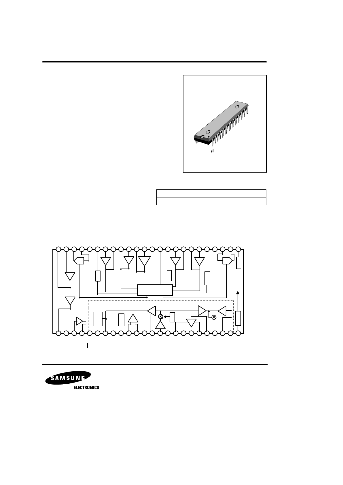
The KA8601C is a monolithic integrated circuit for use in high performance speaker phone system.
The KA860lC consists of speaker phone and speech network. Speaker
phone includes attenuators, amplifiers, level detectors, attenuator
control, hybrid amplifiers, regulator and AGC circuit. Speech network
includes transmit amp, receive amp, voltage regulator for dialer, side
tone control, and line equalizer.
FEATURES
• Speaker Phone
- Low Operating Voltage (3.0 ~ 6.5V)
- High Attenuator Gain Range (52dB)
- Improved Sensitivity (Four-point Signal Sensing)
- Chip Disable for Active or Standby Operation
- Microphone Amp Gain set by External Components
• Speech Network
- Low Operating Voltage (1.5V : speech)
- Regulated Voltage for Dialer (Typically 3.3V)
- Transmit, Receive, Side Tone Gains set by
External Components
- Mute Input for DTMF Dialing
KA8601C 48-SDIP-600
BLOCK DIAGRAM
TX1
RX1
DTO48
GND
44
RX1
PD RXDETI
43
42
ATT
ATT
RXO
RXI
DTI
47
46
45
DETO
41
DETO
40
TX1
DETI
39
MICO
38
MICIMTVC
36
37
35
48-SDIP-600
Device Package Operating Temperature
- 25°C ~ + 75°C
TX2
RX2
RX2
CT
DETI
34
33
DETO
32
DETO
31
TX2
DETI
30
PD TXVB
29
ATT
ATT
DD
TXI
TXO
V
28
27
26
25
hybrid
amp 1
SPEAKER PHONE PART
hybrid
amp 2
1
2
3
DTO+CDFI
RX
FILTER
4
4
FO
Attenuator
5
MT
BNM
DC level
shift
6
VI
SPEECH NET-
WORK PART
8
7
VL
LC
level
detector
1.7Vreg
9
VR
10
MICI-
11
MICI+
mic
amp
12
GND
mic
amp
ATTENUATOR
CONTROLLER
TX
13
MICO
14
TXI
amp2
TX
15
AGC
AGC
AGC
amp1
level
detector
REC
amp
16
17
RXO+NCNC
BNM
sidetone
amp
20
18
19
RXI
RXO-
21
SUM
RXO
TX
Attenuator
RX
22
ZB
amp
3.3Vreg
POWER
23
24
CC
V
MS
Page 2
KA8601C SPEAKER PHONE WITH SPEECH NETWORK
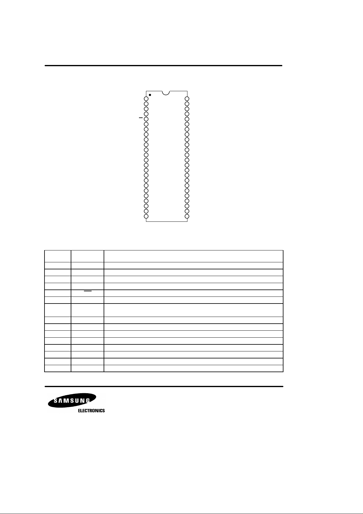
PIN CONFIGURATION
1
DTO+
2
CD
3
FI
4
FO
5
R4
6
V
I
7
VL
8
L
C
9
VR
10
MICI-
MICI+
GND
MICO
AGC
RXO+
RXO-
RXI
RXO
SUM
V
KA8601C
11
12
13
14
TXI
15
16
17
NC
18
NC
19
20
21
22
Z
B
23
MS
24
CC
48
47
46
45
44
43
42
41
40
39
38
37
36
35
34
33
32
31
30
29
28
27
26
25
Fig. 2
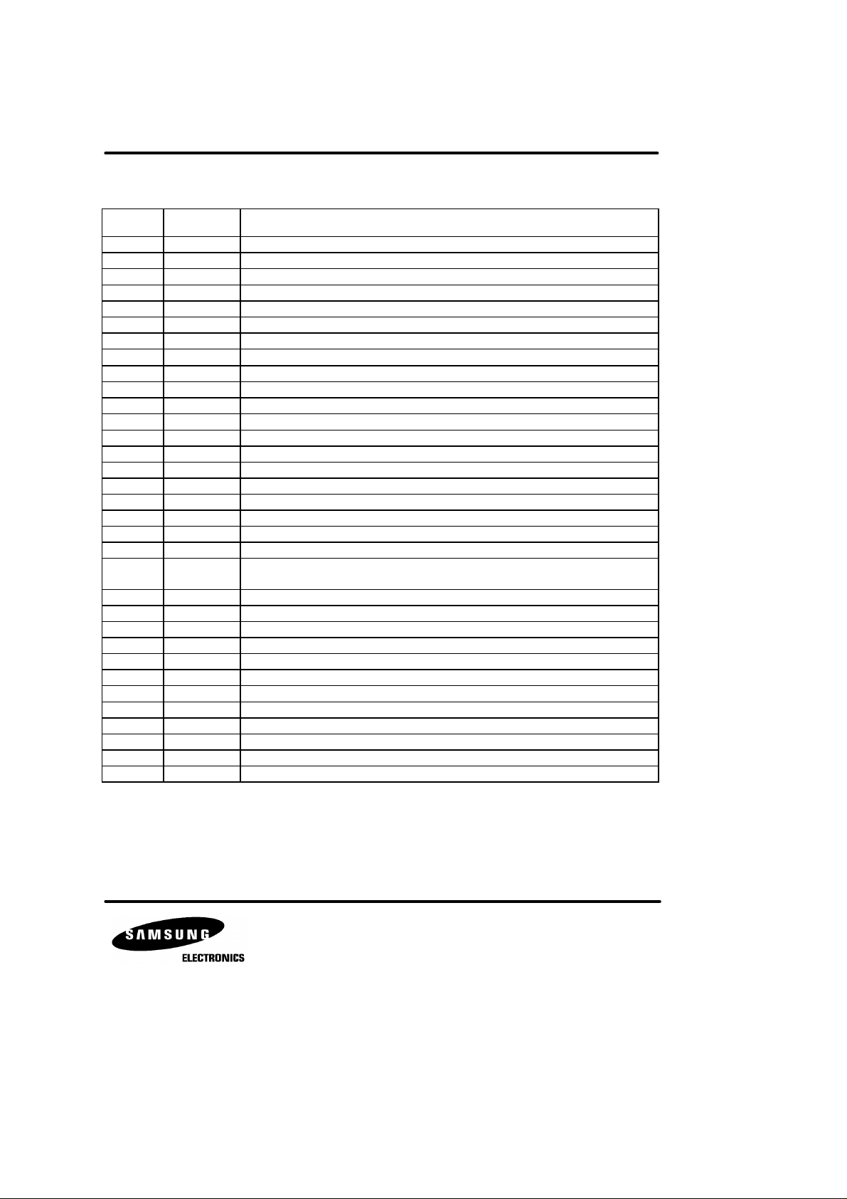
PIN DESCRIPTION
Pin No Symbol Description
1 DTO+ Output of the second hybrid amplifier.
2 CD Chip Disable. A logic low (<0.8V) sets normal operation.
3 FI Filter input.
4 FO Filter output.
5 MT Mute input. A logic “1” sets normal speech mode.
6 V
7 V
8 L
9 V
I
L
C
R
10 MICI- Inverting differential input to the mic amp.
11 MICI+ Non-inverting differential input to the mic amp.
12 GND Ground pin for the speech network.
13 MICO Mic amp output.
14 TXI Input to the TX amp from the Mic amp.
15 AGC Loop current sensing input.
A resistor connected from this pin to VSS sets the AC terminating impedance.
Power supply for the speech network. Supply voltage is derived from loop current.
TX amp output operates on this pin.
Resistor at this pin set the DC characteristics of the circuit.
A 1.7 volt regulated output which can be used to bias the mic.
DTODTI
ATT
RXO
RXI
ATT
GND
PD
RX
DETIRX1
DETO
DETOTX1
DETI
TX1
MICO
MICI
MT
V
C
CT
DETIRX2
DETO
DETO
DETI
TX2
PD
TX
V
B
TXI
ATT
TXO
ATT
V
DD
RX1
RX2
TX2
Page 3
KA8601C SPEAKER PHONE WITH SPEECH NETWORK
PIN DESCRIPTION (continued)
Pin No Symbol Description
16 RXO+ RX amp non-inverting differential output.
17 NC No connection.
18 NC No connection.
19 RXO- RX amp inverting differential output.
20 RXI Input to the RX amp.
21 RXO
22 Z
SUM
B
23 MS
24 V
25 V
26 TXO
27 TXI
28 V
29 PD
CC
DD
ATT
ATT
B
TX
30 DETITX2 Input to the TX level detector on the mike/speaker side.
31 DETOTX2 Output of the TX level detector on the mike/speaker side.
32 DETORX2 Output of the RX level detector on the mike/speaker side.
33 DETIRX2 Input to the RX level detector on the mike/speaker side.
34 C
35 V
T
C
36 MT
37 MICI Input and summing node of the mic amp.
38 MICO Output of the mic amp is set by external resistors.
39 DETTX1 Input to the TX level detector on the line side.
40 DETOTX1 Output of the TX level detector on the line side.
41 DETORX1 Output of the RX level detector on the line side.
42 DETIRX1 Input to the RX level detector on the line side.
43 PD
RX
44 GND Ground pin for the speaker phone part.
45 RXI
46 RXO
ATT
ATT
47 DTI Input and summing node of the mic amp.
48 DTO - Output of the first hybrid amplifier.
Summed output of the RX current amp.
Input to the RX current amp.
Mode select input. A logic “1” → pulse dialing, A logic “0” → tone (DTMF) dialing.
A supply voltage pin for the speaker phone part.
A regulated 3.3 volt output for an external dialer.
Output of the TX attenuator.
Input to the TX attenuator.
This voltage is a system AC ground, and biases the volume control. A filter cap is required.
An RC at this pin sets the time constant for the TX background monitor.
This pin sets the response time for the circuit to switch modes.
Volumn control input.
Mute input. A logic low (<0.8V) sets normal operation. A logic high (>2.0V) mutes the
mic amp.
A RC at this pin sets the time constant for the RX background monitor.
Input to the RX attenuator and dial tone detector.
Output of the RX attenuator.
Page 4

KA8601C SPEAKER PHONE WITH SPEECH NETWORK
ABSOLUTE MAXIMUM RATINGS
Characteristic Symbol Value Unit
Supply Voltage
Speaker
Phone
Voltage at V
C
Voltage at CD,MT
Voltage at TXI, RXI, HFI
Supply Voltage
Speech
Network
Supply Voltage for dialer
Voltage at MTS, MS
Current Through VL, L
Current into Z
B
C
Operating Temperature T
Storage Temperature T
ELECTRICAL CHARACTERISTICS (Ta = 25°C)
Characteristic Symbol Test Conditions Min Typ Max Unit
SPEECH NETWORK (Ta = 25°C, unless otherwise noted)
Line Voltage V
VR Voltage V
MF Operating Voltage
MF Operating Current (Max) I
MICO Bias Voltage V
TXI Bias Voltage V
MIC Amp Gain G
MIC Common Mode
Rejection Ratio
MIC Gain Reduction
TX Gain
TX Distortion THD
RX Gain
RX Distortion THD
Side Tone Gain G
L
R
V
DD (MF)
DD MF (MAX)IL
BIAS (MPO)IL
BIAS (TxTs)IL
V (MIC)IL
CMRR
(MIC)
∆G
V (MIC)
G
V (TX)
TXIL
G
V (RX)
RXIL
V (ST)
V
CC
V
I (VC)
V
I (CM)
V
I (TRH)
V
CC
V
DD
V
I (MS)
I
I (VL, LC)
I
I (ZB)
OPR
STG
- 1.0 ~ + 7.0
- 1.0 ~ VCC + 0.5
-1.0 ~ VCC + 1.0
- 0.5 ~ VCC + 0.5
- 1.0 ~ + 12
- 1.0 ~ + 6.0
- 1.0 ~ VDD + 0.5
130
3
- 25 ~ + 75
- 65 ~ + 150
V
V
V
V
V
V
V
mA
mA
°C
°C
Speech Mode IL = 30mA 3.0 3.9 4.7
Pulse Mode IL = 120mA 8 9.8 11.5
Tone Mode IL = 30mA 4.4 5.1 6.5
IL = 30mA Speech Mode 1.55 1.7 1.85 V
VL = 4.5V Tone Mode 3.0 3.3 3.8
Tone Mode IDD = 1.6mA 3.0 3.3 3.8
Speech Mode 0.5 1.1 2.0
= 30mA Pulse Mode 2 2.8 4
mA
Tone Mode 2 2.8 4
= 30mA Speech Mode 0.8 1.08 1.4 V
= 30mA Speech Mode 0.04 0.086 0.2 V
= 30mA Speech Mode 27 30 33 dB
-
30 64
-
dB
MT = 0V -10 -60 - dB
Speech Mode
IL = 30mA 30 34.8 60
IL = 80mA 28 31 34
dB
= 30mA Speech Mode - - 2 %
Speech Mode
IL = 30mA -15 -10.5 -2
IL = 80mA -17 -14 -10
dB
= 30mA Speech Mode - - 2 %
IL = 30mA Speech Mode - 10 15 dB
V
V
Page 5

KA8601C SPEAKER PHONE WITH SPEECH NETWORK
ELECTRICAL CHARACTERISTICS (Continued)
Characteristic Symbol Test Condition Min Typ Max Unit
Side Tone Rejection RST 20 25 - dB
MUTE Input Impedance Z
MUTE Input Low Voltage
MUTE Input High Voltage
MS Input Low Voltage
MS Input High Voltage
LC Level Shift
I (MUTE)
V
IL (MUTE)
V
IH (MUTE)
V
IL (MS)
V
IH (MS)
∆ V
LC
IL = 30mA Pulse Mode 2.1 2.9 3.5
SPEAKER PHONE (Ta = 25°C, VCC = 5.0V, unless otherwise noted)
Operating Current
Reference Voltage V
I
CC
REF
VCC = 6.5V
VCC = 3.5V - 1.3 VC = V
B
RX Attenuator Gain G
ATT (RX)
VCC = 3.5V, VC = V
VCC = 2.8V, VC = V
RX Attenuator Gain Change
RX Attenuator AGC Gain Change
RX Attenuator Gain (Idle Mode) G
RX Attenuator Gain Range G
RX Volume Control Range G
RX DC Output Voltage V
RX DC Output Voltage Change
RX DC Output High Voltage V
RX DC Output Low Voltage
(with respect to VB)
∆G
∆G
ATT AGC (RX)
ATT RX (IM)
V CTL (RX)
∆V
V
ATT (RX)
ATT (RX)
O (RX)
OH (RX)
OL (RX)
RX Mode Distortion THD
O (RX)
VCC = 3.5V, to 5.0V -0.5 0 +0.5 dB
VCC = 2.8V, to 5.0V - -25 -15 dB
VC = V
B
VC = VB (RX to TX Mode) 49 52 54 dB
VC = 0.1V
B
RX to TX Mode -
V
= 3.5V 3.7 - - V
RXI
V
= 1V
RXI
RX
RX Mode - +240 CT Voltage (with respect to VB) V
CT
Idle Mode - 0 - mV
TX Mode - -240 Dial Tone Detector Threshold V
TX Attenuator Gain G
TX Attenuator Gain Range G
TX Output DC Voltage V
TX Output DC Voltage Change
TH (DET)
ATT (TX)
ATT (TX)
∆V
O (TX)
O (TX)
VC = VB, V
RXI
Speech Mode 2.1 2.9 3.5
Tone Mode 3.4 4.3 5.2
CD = 0.8V - 5.5 8.0
CD = 2V - 0.6 0.8
IL = 1.0mA 1.5 1.7 1.9
B
B
= 3.0V 10 15 20 mV
- 60 -
-
V
DD
1.0
-
-0.3
-
2.0
0.8
-
1.8 2.1 2.4
4.0 6.0 8.0
4.0 6.0 8.0 dB
- -19 -11
-22 -20 -17 dB
27 35 - dB
- V
- V
B
± 10 ±150
-
-1.5 -1.0 V
- 0.5 3 %
4.0 6.0 8.0 dB
49 52 54 dB
- V
-
± 30 ±150
- V
B
KΩ
V
V
mA
V
mV
mV
Page 6

KA8601C SPEAKER PHONE WITH SPEECH NETWORK
ELECTRICAL CHARACTERISTICS (Continued)
Characteristic Symbol Test Conditions Min Typ Max Unit
TX Output High Voltage V
TX Output Low Voltage V
OH (TX)
OL (TX)
TX Mode Distortion THD
MIC Voltage Gain G
MIC Output Offset Voltage V
MIC Output High Voltage V
MIC Output Low Voltage V
MIC Input Bias Current I
Muting (Gain) G
V (MIC)
OO (MIC)
OH (MIC)
OL (MIC)
BIAS (MIC)
V (MUTE)
MIC Amp Distortion THD
MUTE Input High Voltage V
MUTE Input Low Voltage V
Open Loop Gain (Hybrid Amp) G
DTO-Output High Voltage V
DTO-Output Low Voltage V
DTO+Output High Voltage V
DTO+Output Low Voltage V
IH (MUTE)
IL (MUTE)
V (HA)
OH (DTO -)
OL (DTO -)
OH (DTO +)
OL (DTO +)
DTO Distortion THD
Filter Offset Voltage V
Filter Input Bias Current V
IO (F)
BIAS (F)
DTO
TX
MIC
V
= 3.5V 3.7 - - V
TXI
V
= 1.0V - 0.5 1 V
TXI
- 0.8 3 %
70 80 - dB
-50 0 +50 mV
V
= 1.0V 3.7 - - V
MIC
V
= 3.0V - - 200 mV
MIC
- -40 - nA
VMT = 2V, f = 1KHz -55 - - dB
- 0.15 - %
0.3KHz ≤ f ≤ 10KHz
2.0 - V
CC
0 - 0.8 V
60 80 - dB
3.7 - - V
- - 250 mV
IO = -5mA 3.7 - - V
IO = 5mA - - 250 mV
IO = -5mA - 0.3 - %
IO = 5mA -22 -90 0 mV
0 -50 - mA
V
Page 7

KA8601C SPEAKER PHONE WITH SPEECH NETWORK
APPLICATION INFORMATION
FUNCTION DESCRIPTION
SPEECH NETWORK
1. MICROPHONE AMPLIFIER
This microphone amplifier is equipped with a fixed gain (30dB). Its basic configuration is shown in figure 3.
MICI+
MIC-
20K 20K
Fig .3
This amplifier has a mute function. If a mute signal from the dialer is inputted when the speech network is in the mute
mode, the microphone amplifier will be muted.
2. VOLTAGE REGULATOR (DIALER INTERFERENCE)
This voltage regulator has a minimum output voltage of 3.1 volts. When the dialer is not in motion, its minimum current
is 1.0mA, where as when the dialer is moving the minimum current is 2.2mA.
3. VOLTAGE REFERENCE
Generally when in the voltage reference mode, the microphone's bias voltage is used, but when in the TXl
DC bias voltage is used. The output voltage of the voltage reference is a minimum of 1.6 volts.
SPEAKER PHONE
1. MICROPHONE AMPLIFIER
This device amplifies outside microphone signals, which are inputted while in the inverting mode. As it alters elements,
the microphone amplifier allows for them to be modulated. Its open loop gain is 80dB, while the band width is typically
1.0KHz. It has a mute function, and when operating in the mute mode at least 2.0V, the microphone amplifier gain
is reduced to around 40dB. If the mute mode is not used, it must connected with the ground.
+
-
30dB
Rf
MT
MICO
ATT
mode,
MIC
Fig. 4
Ri
Bias Voltage
-
+
MICO
MT
Page 8

KA8601C SPEAKER PHONE WITH SPEECH NETWORK
2. VOLUME CONTROL
The volume control can only be applied in the receive mode. If the voltage of the VC mode is the same as the VB, the
receive attenuator gain is maximized and the transmit gain is minimized. At the same time, if the VC mode voltage is
less than the VB, the receive attenuator gain is reduced.
V
B
V
KA8601C
Fig. 5
3. VOICE DETECTION FUNCTION
The voice detection function compares the microphone amplifier output level with the outside audio amplifier level
and the transmit attenuator output level with the receive attenuator input level, after which they are inputted into the
control box. The block diagram of the voice detection function is as follows:
C
VOLUME
DETIRX1
DETORX1
A1
Log Amp
PD
Comparator
RX
Background
Noise Monitor
PD
TX
Comparator
DETOTX1
A3
Log Amp
DETI
TX
1
C1 C2
DETITX1
Log Amp
A2
DETOTX1
CO1 CO2
Attenuator Control Box
CO4CO3
DETOTX1
Log Amp
A4
DETI
1
RX
Fig. 6
It is useful to use a background noise monitor when high background noise occurs. When the input signals to the
background noise monitor are increased, voltage for the PDRX (PDTX) mode is stably increased. The increase time
is determined by 100KΩ and 47µF.
4. ATTENUATOR CONTROL BOX
In figure 6, each signal coming into the log amplifier is amplified and then inputted into the comparator (C1, C2). The
comparator compares the amplified signal levels, after which they are inputted into the attenuator control box. The
attenuator control box processes these signals (CO1, CO2, CO3, CO4) as logic signals, and which are put into one
of the following modes:
Page 9

KA8601C SPEAKER PHONE WITH SPEECH NETWORK
1. Receive Mode
2. Transmit Mode
3. Slow Idle Mode
4. Fast Idle Mode
Which of the above modes is to be determined depending on the following conditions:
1) Receive Mode
DETOTX1 < DETORX1, DETOTX2 < DETORX2, PDTX, X, PDRX : 1
2) Transmit Mode
DETOTX1 > DETORX1, DETOTX2 > DETORX2, PDTX : 1, PDRX : X
3) Slow Idle Mode
DETOTX1 > DETORX1, DETOTX2 > DETORX2, PDTX : 0, PDRX : X
DETOTX1 < DETORX1, DETOTX2 < DETORX2, PDTX : 0, PDRX : X
DETOTX1 < DETORX1, DETOTX2 > DETORX2, PDTX : 0, PDRX : X
DETOTX1 > DETORX1, DETOTX2 < DETORX2, PDTX : 0, PDRX : X
4) Fast Idle Mode
DETOTX1 > DETORX1, DETOTX2 < DETORX2, PDTX : 0, PDRX : 0
DETOTX1 < DETORX1, DETOTX2 > DETORX2, PDTX : Y, PDRX : Y
* "<" and ">" refer to voltage level : "X" refers to "It doesn't matter : "Y" is not zero
5. SWITCHING TIME
The switching time of the speaker phone is determined by the CT and RT of the outside elements.
1. Idle Mode → RX or TX Mode
ST = 4,000 X C
2. TX or RX Mode → Fast Idle Mode
ST = 2,000 X C
3. TX or RX Mode → Slow Idle Mode
ST = RT X C
* CT, RT refer to the capacitor and resistor between Pin 34 and VCC.
T
T
T
Page 10

KA8601C SPEAKER PHONE WITH SPEECH NETWORK
APPLICATION CIRCUIT
 Loading...