

Page 1
CoolMOS Power MOSFET
V
DSS
I
D25
R
DS(on)
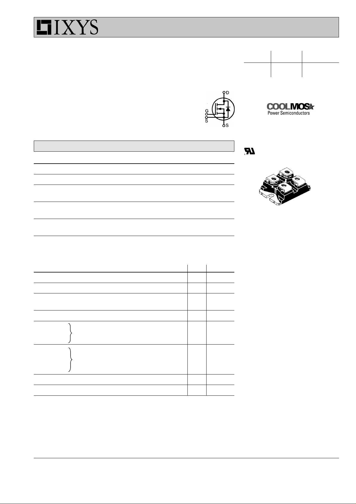
IXKN 75N60C
N-Channel Enhancement Mode
Low R
Preliminary
MOSFET
Symbol Conditions Maximum Ratings
V
DSS
V
GS
I
D25
I
D90
dv/dt VDS < V
E
AS
E
AR
DSon
, High V
MOSFET
DSS
TVJ = 25°C to 150°C 600 V
±20 V
TC = 25°C 75 A
TC = 90°C 50 A
; IF ≤ 100A;diF/dt≤ 200A/µs 6 V/ns
DSS
TVJ = 150°C
ID = 10 A; L = 36 mH; TC = 25°C 1.8 J
ID = 20 A; L = 5 µH; TC = 25°C 1 mJ
600 V 75 A 35 m
miniBLOC, SOT-227 B
E72873
S
G
S
D
G = Gate D = Drain
S = Source
Either source terminal at miniBLOC can be used
as main or kelvin source
ΩΩ
Ω
ΩΩ
Symbol Conditions Characteristic Values
(TVJ = 25°C, unless otherwise specified)
min. typ. max.
R
V
I
DSS
I
GSS
Q
Q
Q
t
d(on)
t
r
t
d(off)
t
f
V
R
DSon
GSth
g
gs
gd
F
thJC
VGS = 10 V; ID = I
D90
30 35 mΩ
VDS = 20 V; ID = 5 mA; 3.5 5.5 V
VDS = V
= 0 V; TVJ = 25°C 0.05 mA
DSS; VGS
TVJ = 125°C 0.1 mA
VGS = ±20 V; VDS = 0 V 200 nA
440 nC
VGS= 10 V; VDS = 350 V; ID = 100 A
112 nC
246 nC
30 ns
VGS= 10 V; VDS = 380 V;
ID = 50 A; RG = 1 Ω
95 ns
100 ns
10 ns
(reverse conduction) IF = 37.5 A; VGS = 0 V 0.9 1.1 V
0.22 K/W
Features
●
miniBLOC package
- Electrically isolated copper base
- Low coupling capacitance to the heatsink for
reduced EMI
- High power dissipation due to AlN
ceramic substrate
- International standard package SOT-227
- Easy screw assembly
●
fast CoolMOS power MOSFET - 2nd generation
- High blocking capability
- Low on resistance
- Avalanche rated for unclamped
inductive switching (UIS)
- Low thermal resistance
due to reduced chip thickness
●
Enhanced total power density
Applications
●
Switched mode power supplies (SMPS)
●
Uninterruptible power supplies (UPS)
●
Power factor correction (PFC)
●
Welding
●
Inductive heating
CoolMOS is a trademark of
Infineon Technologies AG.
IXYS reserves the right to change limits, test conditions and dimensions.
© 2001 IXYS All rights reserved
130
1 - 3
Page 2
IXKN 75N60C
Component
Symbol Conditions Maximum Ratings
V
ISOL
T
VJ
T
stg
M
d
I
≤ 1 mA; 50/60 Hz 2500 V~
ISOL
-40...+150 °C
-40...+125 °C
mounting torque 1.5 Nm
terminal connection torque (M4) 1.5 Nm
Symbol Conditions Characteristic Values
min. typ. max.
R
thCH
with heatsink compound 0.1 K/W
Weight 30 g
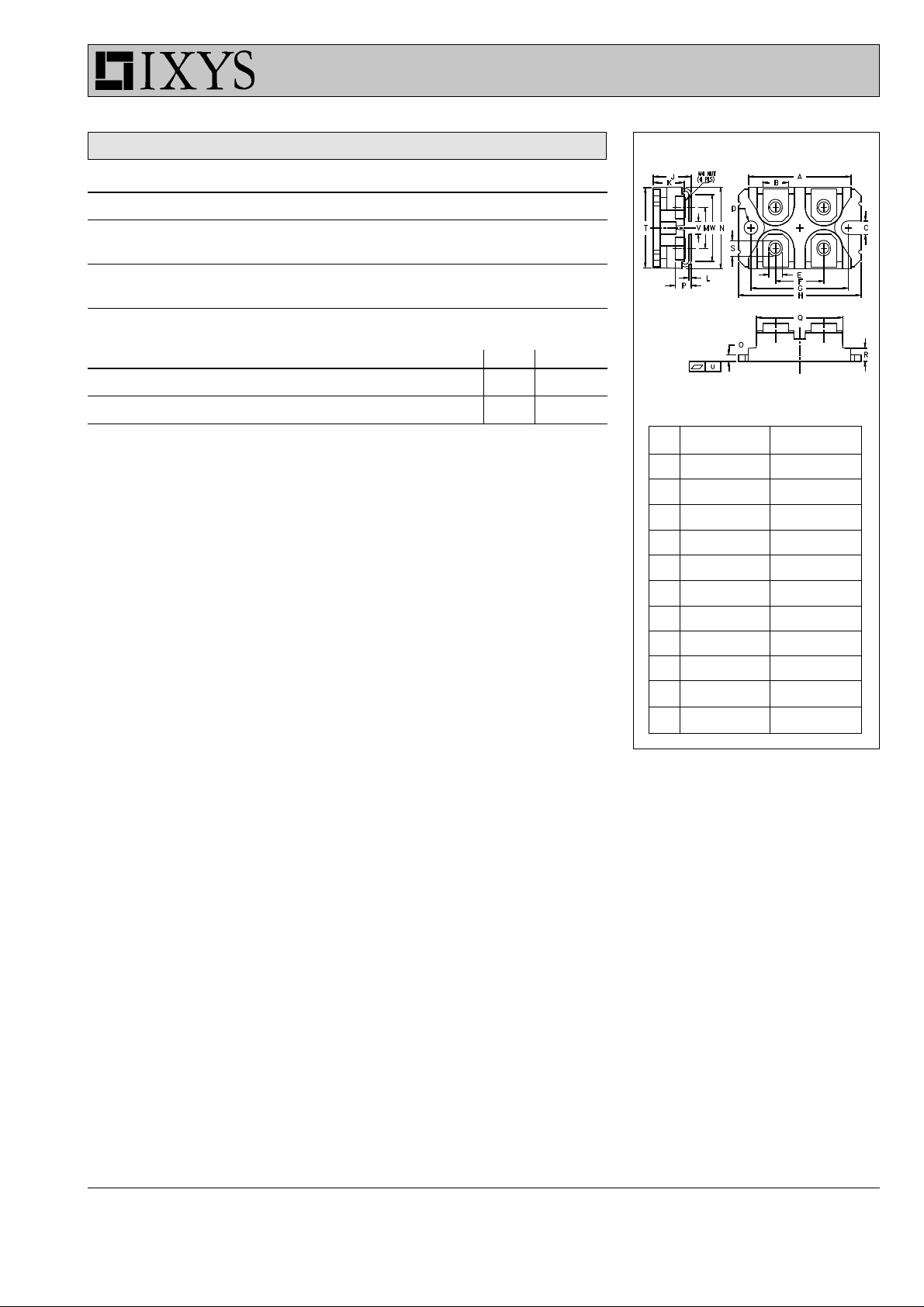
miniBLOC, SOT-227 B
M4 screws (4x) supplied
Dim. Millimeter Inches
Min. Max. Min. Max.
A 31.50 31.88 1.240 1.255
B 7.80 8.20 0.307 0.323
C 4.09 4.29 0.161 0.169
D 4.09 4.29 0.161 0.169
E 4.09 4.29 0.161 0.169
F 14.91 15.11 0.587 0.595
G 30.12 30.30 1.186 1.193
H 37.80 38.20 1.489 1.505
J 11.68 12.22 0.460 0.481
K 8.92 9.60 0.351 0.378
L 0 .76 0.84 0.030 0.033
M 12.60 12.85 0.496 0.506
N 25.15 25.42 0.990 1.001
O 1.98 2.13 0.078 0.084
P 4.95 5.97 0.195 0.235
Q 26.54 26.90 1.045 1.059
R 3.94 4.42 0.155 0.174
S 4.72 4.85 0.186 0.191
T 24.59 25.07 0.968 0.987
U -0.05 0.1 -0.002 0.004
V 3.30 4.57 0.130 0.180
W 0.780 0.830 19.81 21.08
© 2001 IXYS All rights reserved
2 - 3
Page 3

IXKN 75N60C
250
A
V
= 18 - 12 V
GS
10 V
200
I
D
TVJ = 25°C
150
8 V
100
50
0
0 4 8 12 16 20
V
DS
V
Fig. 1: typ. Output Characteristics Fig. 2: typ. R
0.10
Ω
0.08
R
DSon
0.06
ID = 50 A
R
I
0.16
VGS = 8 V
Ω
0.12
DSon
TVJ = 25°C
0.08
0.04
0.00
0 50 100 150 200 250
vs. Drain Current
DSon
250
A
200
D
TVJ = 25°C
150
10 V
12-18 V
I
D
TVJ = 125°C
A
0.04
0.02
0.00
-40 0 40 80 120 160
Fig. 3: typ. R
vs. Junction Temperature Fig. 4: typ. Input Admittance
DSon
16
V
14
12
V
GS
10
8
6
4
2
0
0 100 200 300 400 500 600 700
Fig. 5: typ. Gate Charge Characteristic Curve
100
50
0
°C
T
VJ
024681012
V
GS
V
1
K/W
0.1
Z
thJC
0.01
single pulse
0.001
nC
Q
G
0.000010.0001 0.001 0.01 0.1 1 10
0.0001
IXKN75N60C
s
t
Fig. 6: typ. Transient Thermal Impedance
© 2001 IXYS All rights reserved
3 - 3
 Loading...