

Page 1

i-Screen Ev1
Part # MAN-i-Screen
$95.00 USD
i-Screen™
V.081210
Page 2

Page 3
i-Screen™
V.081210
Contents
1. Safety and Operational Guidelines 4
1.1 Management Responsibilities..................................................................................................................5
1.2 Operator Responsibilities.........................................................................................................................6
2. General Information 7
2.1 Service and Parts.....................................................................................................................................8
2.2 Defined Purpose ......................................................................................................................................9
2.3 Warranty...................................................................................................................................................10
3. Specifications 11
4. Assembly and Setup 11
4.1 Assembly..................................................................................................................................................11
4.1.1 Level............................................................................................................................................11
4.1.2 Install Computer ..........................................................................................................................12
4.1.3 Attach Computer Monitor.............................................................................................................13
4.1.4 Connect Power to Computer and Printer ....................................................................................13
4.1.5 Install Covers...............................................................................................................................14
4.1.6 Connect Compressed Air ............................................................................................................14
4.1.7 Fill Ink and Cleaning Fluid Tanks................................................................................................14
4.1.8 Install/Change Screen Pusher.....................................................................................................15
4.1.9 Install Foot Pedal.........................................................................................................................15
5. Operation 16
5.1 Main Control Panel ..................................................................................................................................16
5.1.1 Printer Control Panel...................................................................................................................18
5.1.2 Operator Interface .......................................................................................................................20
5.2 Start Up....................................................................................................................................................26
5.3 Load Screen.............................................................................................................................................27
5.4 Install i-Screen PPD File into Illustrator ...................................................................................................28
5.5 Opening Adobe Illustrator Files for Separation........................................................................................33
5.6 Printing.....................................................................................................................................................37
5.7 Unload Screen .........................................................................................................................................41
5.8 Shutdown.................................................................................................................................................41
6. Troubleshooting 42
6.1 Printer Control Panel................................................................................................................................42
7. Scheduled Maintenance 43
7.1 Scheduled Maintenance Log ...................................................................................................................56
8. Replacement Parts 57
M&R Companies 1N 372 Main St. Glen Ellyn, IL 60137 USA 3
Tel: +630-858-6101 Fax: +630-858-6134 www.mrprint.com
| store.mrprint.com
Page 4

i-Screen™
V.081210
1. Safety and Operational Guidelines
DANGER
This symbol identifies situations that endanger people, property, and/or equipment. If such condition s
exist, the equipment must be shut down and all energy sources (electrical, gas, and pneumatic) mu st be
disconnected, purged, and locked out until the problem is resolved.
Never attempt to bypass or defeat any safety device. Do not attempt to operate the equipment if any safety
device is not functioning properly, or if any doubt exists about proper operation of safety devices.
The product described in this publication may operate at high speed and contain numerous moving parts.
It may employ natural gas or propane, mechanical or pneumatic forces, and/or hazardous voltages, and may
create other conditions that could, through misuse, abuse, unauthorized alteration or retrofitting, inattention, or
lack of understanding, result in injury, death, or damage to the product or to other equipment. In addition,
improper operation may also depreciate the value of the machine and other assets of the owner, and impair the
working efficiency of the machine.
Energy Sources
M&R equipment may use one of more of the following energy sources:
Compressed Air (Pneumatic Energy)
Electricity
Gas (Natural Gas or Propane)
Each form of energy presents its own unique hazards and requires appropriate precautions.
Danger From Compressed Air (Pneumatic Energy)
Only qualified personnel should be allowed to work on pneumatic components or assemblies. Before work is
started on pneumatic components or assemblies, equipment should be disconnected from the air supply and all
pneumatic lines should be purged to prevent accidental operation of pneumatic assemblies. All pneumatic pipe s
and hoses should be checked frequently for damage and wear.
Danger From Electrical Energy
Only qualified personnel should have access to electrical enclosures or work on electrical systems, and
enclosures should be locked when not in use. Electrical equipment should be checked regularly.
WARNING
Failure to follow safety and maintenance procedures or to take appropriate corrected action when required can
result in severe or fatal personal injuries, property damage, and/or damage to the equipment.
4 M&R Companies 1N 372 Main St. Glen Ellyn, IL 60137 USA
Tel: +630-858-6101 Fax: +630-858-6134 www.mrprint.com
| store.mrprint.com
Page 5

i-Screen™
1.1 Management Responsibilities
1. Ensure that this equipment is used only for the purposes set forth in the “Defined Purpose” section of
this manual.
2. Ensure that all employees involved with the operation of this equipment or working near it read,
understand, and act in accordance with the operational and safety standards set forth in this manual,
including the Operator Responsibilities listed below.
3. Ensure that all recommended preventive maintenance is carried out according to M&R guidelines.
4. Should any problem arise which compromises the safe operation or normal functioning of this
equipment, ensure that the equipment is immediately shut down, sources of power to the equipment is
shut off and secured, and that personnel not trained to repair - and directly involved in repairing - the
equipment are removed from the immediate area and not allowed to return until the equipment has been
returned to a safe and fully-functional condition.
5. Provide, and compel use of, any personal protection devices that may be required for the safe operation
of this equipment.
6. Make no modification to equipment o r eq uipment software without written approval from M&R.
7. Provide - and supp ort with written documentation - necessary employee training to ensure safe
operation, including but not limited to instruction in:
V.081210
a. the operation of this machine
b. the use of personal protection devices
c. preventive maintenance procedures
M&R Companies 1N 372 Main St. Glen Ellyn, IL 60137 USA 5
Tel: +630-858-6101 Fax: +630-858-6134 www.mrprint.com
| store.mrprint.com
Page 6

i-Screen™
V.081210
1.2 Operator Responsibilities
Note: 'Operator Responsibilities' pertain to all employees who work on or near the equi pment; this
includes, but is not limited to those who clean, maintain and repair the equipment as well as those who
operate it. In general, all those who work on or near the equipment have a duty to use reasonable and
ordinary care for their own safety when in the vicinity of the machine. Failure to use reasonable and
ordinary care subjects people and property to serious personal injury and/or death and to destruction of
personal and/or company property. M&R expressly disclaims any and all liability, whether in contract, tort
or by statute, for damages, whether in the nature of personal injury/death and/or property damage, and
whether direct, indirect, consequential or incidental, as a result of a failure to use reasonable and
ordinary care.
1. Ensure that this equipment is used only for the purposes set forth in the “Defined Purpose” section of
this manual.
2. Read, understand, and act in accordance with the safety and operat ional standards and guidelines set
forth in this manual.
3. Install and maintain the equipment and safety devices in accordance with this manual; this includes
checking the equipment and safety devices for external or visible damage at least once per shift, and
making sure all safety and danger notices are in place and in readable condition.
4. Make no modification to equipment o r eq uipment software without written approval from M&R.
5. Ensure that all other empl oyees working on or near this equipment are knowledgeable in its safe
operation, and closely supervise inexperienced employees; keep bystanders away from the equipment.
6. Make sure th e area around the equipment is clear and free of obstructions, clean up spills immediately,
and remove ink and other contaminants at the end of each shift.
7. Ensure that any and all saf ety guards (including but not limited to safety bar, foot switch, yellow cycle
interruption cords, infrared safety beam or hand switches) provided with this equipment for the purpose
of protecting personnel by automatically stopping the equipment are in place - and are not removed,
disabled or rendered ineffective during operation.
8. Wear any personal prote cti on devices required for the safe operation of this equipment.
9. Avoid wearing anything that could b eco me entangled in moving parts; for example, but not by way of
limitation, tie back, pin up, or cover long hair.
10. Do not attempt to operate this equipment if you are sick, fatigued, or under the influence of alcohol
and/or drugs including, but not limited to, prescriptions and over-the-counter medications that warn
against the operation of equipment.
11. Avoid standing on any part of the equipment not intended for that purpose.
12. Immediately shut down the equipment, disconnect and lock out all sources of power (electrical, gas,
and/or pneumatic); and purge all lines under pressure if the equipment fails to be fully operational or if
any safety device fails to operate properly, and ensure that the equipment stays offline until the safety
device is again operational.
13. Perform - and document - preventive maintenance at intervals described in the Operator's Manual.
14. Keep this Operator's Manual in clean, easily readable condition near the equipment at all times so it can
be quickly accessed by operators and maintenance personnel.
6 M&R Companies 1N 372 Main St. Glen Ellyn, IL 60137 USA
Tel: +630-858-6101 Fax: +630-858-6134 www.mrprint.com
| store.mrprint.com
Page 7

i-Screen™
V.081210
2. General Information
This Document
This document is based on information available at the time of its publication. While every effort has been made
to be accurate, the information contained herein does not purport to cover all details or variations in hardware,
software, features, or specifications, or to provide for every possible contingency in connection with installation,
operation and maintenance. Features may be described herein which are not present in all models of this
product. M&R Printing Equipment, Inc. and its subsidiaries reserve the right to alter specifications in the
manufacture of their products, and they assume no obligation of notice to holders of this document with respect to
changes subsequently made.
M&R Printing Equipment, Inc. and its subsidiaries make no representation or warranty, expressed or implied,
whether pursuant to statute or case law with respect thereto, and assume no responsibility for, the accuracy,
completeness, sufficiency or usefulness of the information contained herein. No warranties of merchantability or
fitness for a particular purpose shall apply.
This is a publication of M&R Printing Equipment, Inc. and its subsidiaries. All information contained herein is
derived in part from proprietary and patent data of M&R Printing Equipment, Inc., and may not be copied,
electronically reproduced, or transmitted in any form without prior written permission, in each case made and
provided.
Any product names used in the documentation are used for identification only and may be trademarks of their
respective owners. The M&R Companies does not claim any rights to those marks.
M&R Companies 1N 372 Main St. Glen Ellyn, IL 60137 USA 7
Tel: +630-858-6101 Fax: +630-858-6134 www.mrprint.com
| store.mrprint.com
Page 8
i-Screen™
V.081210
2.1 Service and Parts
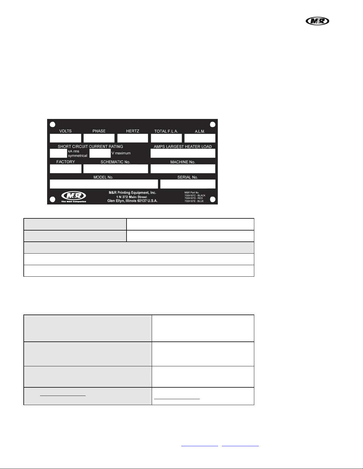
Manufacturer's Rating Plate
Most products manufactured by the M&R Companies have a metal manufacturer's rating plate. Below is a label
imprinted with the information from your product's rating plate. Please be prepared to provide this information
when calling. This helps us respond to your needs more quickly.
If this is a replacement manual, please record the information from your product's rating plate on the sample plate
shown below.
Date Installed
Installed by
Optional Features and Special Information
Contacting M&R
If you need service or have questions about your equipment, call the appropriate number and ask for Technical
Support. If you need parts, ask for the Parts Department.
From the United States & Canada
Monday-Friday between 8:30 AM and 5:00 PM
800-736-6431 Or 630-858-6101
Central Standard/Daylight Time
From all other countries
Monday-Friday between 14:30 and 23:00
+847-967-4461
Greenwich Mean Time (GMT)
Call our Global Hotline:
Outside Regular Hours
+630-462-4715
Visit www.mrprint.com for a list of global
contacts
8 M&R Companies 1N 372 Main St. Glen Ellyn, IL 60137 USA
Tel: +630-858-6101 Fax: +630-858-6134 www.mrprint.com
www.mrprint.com
| store.mrprint.com
Page 9

i-Screen™
V.081210
2.2 Defined Purpose
Textile Presses
Textile Presses are designed to print textile inks on textile substrates, as more fully set forth in the manual specific
to that product. Any other use of this equipment is not permitted.
Textile Dryers
Textile Dryers are designed to cure/dry textile inks on textile substrates, as more fully set forth in the manual
specific to that product. Any other use of this equipment is not permitted.
Graphic Presses
Graphic Presses are designed to print graphic inks on rigid and semi-rigid flat substrates, as more fully set forth in
the manual specific to that product. Any other use of this equipment is not permitted.
Graphic Dryers
Graphic Dryers are designed to cure/dry graphic inks on rigid and semi-rigid flat substrates, as more fully set forth
in the manual specific to that product. Any other use of this equipment is not permitted.
Exposure Equipment
Exposure Equipment is designed to produce photographic printing plates and printing screens, as more fully set
forth in the manual specific to that product. Any other use of this equipment is not permitted.
Folding and Packaging Equipment
Folding and Packaging Equipment is designed to fold, transport, and package textile materials, as more fully set
forth in the manual specific to that product. Any other use of this equipment is not permitted.
Ancillary Equipment
Ancillary Equipment is designed to perform specific operations related to processing and han dling of substrates,
as more fully set forth in the manual specific to that product. Any other use of this equipment is not permitted.
Digital Equipment
Digital Printers are designed to print water based inks on textile substrates and screens, as more fully set forth in
the manual specific to that product. Any other use of this equipment is not permitted.
M&R Companies 1N 372 Main St. Glen Ellyn, IL 60137 USA 9
Tel: +630-858-6101 Fax: +630-858-6134 www.mrprint.com
| store.mrprint.com
Page 10

i-Screen™
V.081210
2.3 Warranty
Limited Warranty
Your Warranty does not apply to damages sustained due to equipment misuse, whether intentional or negligent,
and such misuse may void your warranty. Misuse includes - but is not limited to - the items listed below. In
addition, M&R Printing Equipment, Inc. accepts no responsibility for personal injury or property damage caused by
misuse.
1. Use of the equipment for any non-defined purpose
2. Improper installation or us e of the equipment
3. Operation of the equipment with defectiv e safety devices
4. Operation of the equipment with safety devices removed, disabled, not working in whole or in part or in
any manner rendered ineffective for the purpose for which they were designed
5. Failure to comply with instructio ns for transportation, storage, installation, operation, maintenance,
setup, and take-down of the equipment as described in the Operator's Manual
6. Unauthorized modification of the equipment or equipment software
7. Failure to replace worn or d efective parts
8. Failure to use M&R supplie d replacement and repair parts
9. Defective repairs m ade to the equipment
10. Dangerous conditions which result from improper use of the equipment
10 M&R Companies 1N 372 Main St. Glen Ellyn, IL 60137 USA
Tel: +630-858-6101 Fax: +630-858-6134 www.mrprint.com
| store.mrprint.com
Page 11
i-Screen™
3. Specifications
V.081210
Specifications
Air @ 6,2 bar (90 psi)
Electrical Requirements 1
Maximum Frame Profile
Maximum Frame Size
Maximum Image Area
Overall Size (H x W x D)
Shipping Weight
1
If incoming voltage differs from the voltage(s) listed, calculate amperage accordingly. Other electrical
configurations are available: Contact M&R for details.
208/230 V, 1 ph, 9 A, 60 Hz, 2 kW
203 x 213 x 64 (80" x 84" x 25")
142 l/min (5 cfm)
3.8 x 3.8 cm (1.5" x 1.5")
79 x 109 cm (31" x 43")
64 x 93 cm (25" x 36.5")
340 kg (750 lb)
4. Assembly and Setup
Inspection
Carefully inspect for signs of damage in transit. If equipment has been damaged in transit, notify the Freight
Forwarder immediately. M&R is not responsible for damage that occurs during transportation.
Hardware and Tools
Additional tools required: 9/16” Combination Wrench and Level.
4.1 Assembly
4.1.1 Level
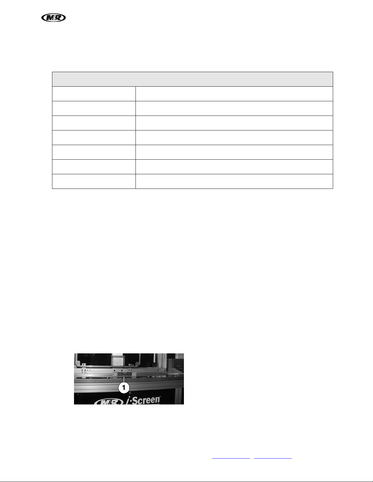
If unit is moved after it is initially setup, it must leveled for correct operation.
1. Place level (1) on cover.
M&R Companies 1N 372 Main St. Glen Ellyn, IL 60137 USA 11
Tel: +630-858-6101 Fax: +630-858-6134 www.mrprint.com
| store.mrprint.com
Page 12
i-Screen™
V.081210
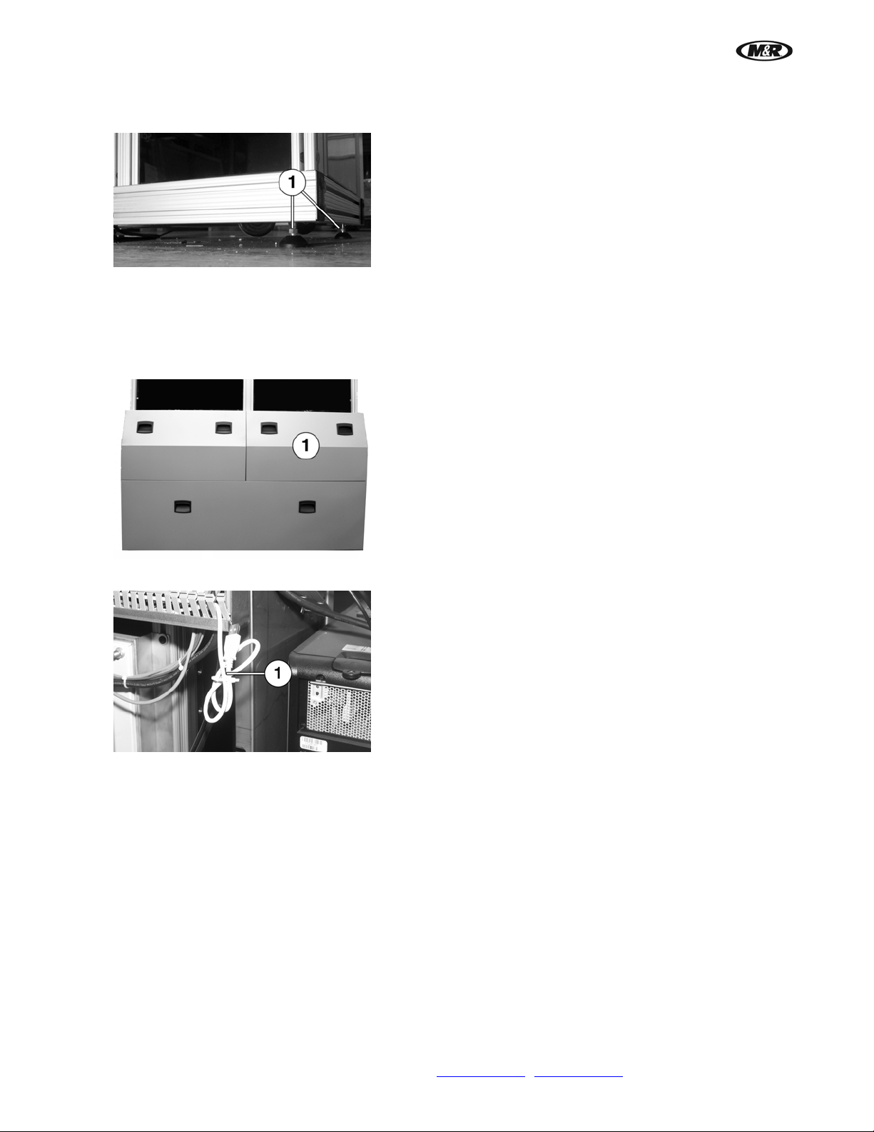
2. Use a 9/16” open end wrench on leveling pads (1) to level. Level the unit side to side and front to back.
After leveling, tighten the lock nut.
4.1.2 Install Computer
1. Unpack computer. Remove upper right cover (1).
2. Place computer components in enclosure on left font side of unit and assemble according to
manufacturers instructions.
3. Locate USB/Printer cable (1) n ear the computer enclosure.
12 M&R Companies 1N 372 Main St. Glen Ellyn, IL 60137 USA
Tel: +630-858-6101 Fax: +630-858-6134 www.mrprint.com
| store.mrprint.com
Page 13

i-Screen™
4.1.3 Attach Computer Monitor
1. Unit is shipped with the bracket (1) attached to the frame and the adapter (2) attached to the monitor
(3). Remove knob (4) and screw (5) and remove bracket (1) from frame. Remove screws (6) from
adapter (2) and reattach bracket and adapter to monitor as shown. Install monitor on frame using knob
(4) and screw (5).
IMPORTANT: Make sure screw (5) is installed. This prevents monitor from falling if knob (4) is
removed. There are two sets of holes on bracket (1) to vary height of monitor. Reverse bracket (1) to
position monitor even higher if more convenient for viewing screen.
V.081210
4.1.4 Connect Power to Computer and Printer
IMPORTANT: Do not plug other items into the same outlet as power fluctuations may cause pr inting
problems.
1. Make sure that both printer and computer are off.
2. Plug the USB/Printer cable into a USB port on the back side of the comp uter (1).
3. Install the i-Block secu rity dongle (2) in a USB port on the back side of the computer tower to avoid
damage.
4. Turn on Computer. Do uble click the i-Block icon on the screen to open the application.
M&R Companies 1N 372 Main St. Glen Ellyn, IL 60137 USA 13
Tel: +630-858-6101 Fax: +630-858-6134 www.mrprint.com
| store.mrprint.com
Page 14
i-Screen™
V.081210
4.1.5 Install Covers
After installing and connecting computer, use hand grips and install any covers removed on back of unit.
4.1.6 Connect Compressed Air
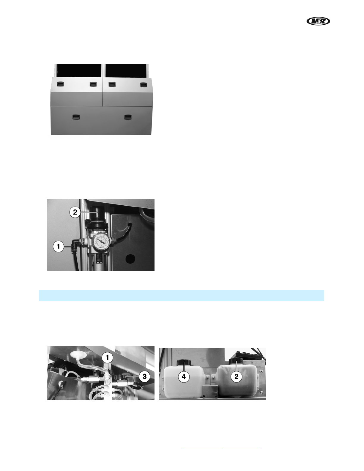
Attach compressed air supply to the Air Fitting (1). The requirement for the compressed air supply to the i-Scre en
is 90 psi @ 5 cfm.
Adjust the incoming air supply pressure to 35 psi. To set the air pressure, pull the knob (2) out. Turn the knob
counterclockwise to decrease the air pressure or turn the knob clockwise to increase the air pressure. Push knob
(2) in to lock air pressure setting.
4.1.7 Fill Ink and Cleaning Fluid Tanks
IMPORTANT: The warranty is void if non M&R ink is used in the printer.
1. Make sure cl eaning fluid valve (1) is closed (at 90 degrees to cleaning fluid line).
2. Remove cap (2) and fill tank with ink. Replace cap.
3. Open ink valve (3) (pa rallel to ink line).
4. Remove cap (4) a nd fill tank with cleaning fluid. Replace cap.
14 M&R Companies 1N 372 Main St. Glen Ellyn, IL 60137 USA
Tel: +630-858-6101 Fax: +630-858-6134 www.mrprint.com
| store.mrprint.com
Page 15

i-Screen™
4.1.8 Install/Change Screen Pusher
1. Loosen thumb scre ws (1) until latch can be rotated.
2. Lift and remove screen pusher (2) and install the new size screen pusher.
IMPORTANT: The size, stamped on the screen pusher frame, should always be positioned in the
upper left-hand corner.
3. Rotate latch and tighten thumb screws (1).
4. When using scre ens with Newman Roller Frames, the bottom right stop block must be positioned under
the corner of the frame (1). To move the stop block, refer to the Scheduled Maintenance section of this
manual.
V.081210
4.1.9 Install Foot Pedal
To connect foot pedal, insert pins into receptacle and twist collar (1) clockwise to lock.
M&R Companies 1N 372 Main St. Glen Ellyn, IL 60137 USA 15
Tel: +630-858-6101 Fax: +630-858-6134 www.mrprint.com
| store.mrprint.com
Page 16

i-Screen™
V.081210
5. Operation
5.1 Main Control Panel
Number Name Function
1
2
16 M&R Companies 1N 372 Main St. Glen Ellyn, IL 60137 USA
Emergency
Stop Button
Reset
Tel: +630-858-6101 Fax: +630-858-6134 www.mrprint.com
The red Emergency Stop button stops all operation.
To activate, press the button in until it remains depressed.
To deactivate, turn the Emergency Stop button right (clockwise) until it pops
out.
Green button resets the control system logic in the event of an emergency stop.
| store.mrprint.com
Page 17

i-Screen™
V.081210
3
Pause
Red button pauses printing. Press button again to resume printing. Press and
hold button for 3 seconds to cancel current print job.
4
5
Operator
Interface
Print Position
Used to display information regarding operational, programming, and system
status messages.
Blue button lowers screen frame to print position.
6
Unload
Yellow button raises screen frame to load/unload position.
Position
7
Printer Control
Panel
The Printer Control Panel is used to turn printer on and off and to view screen
messages.
M&R Companies 1N 372 Main St. Glen Ellyn, IL 60137 USA 17
Tel: +630-858-6101 Fax: +630-858-6134 www.mrprint.com
| store.mrprint.com
Page 18
i-Screen™
V.081210
5.1.1 Printer Control Panel
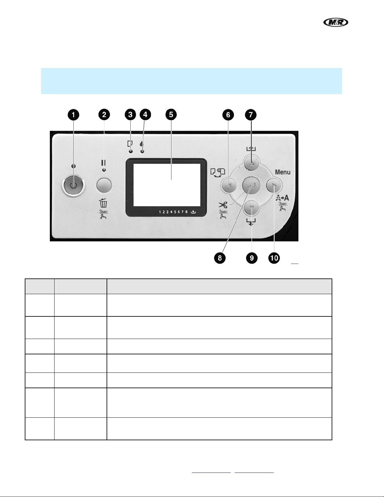
The Printer Control Panel is used to turn printer on and off and to view screen messages.
Note: Some functions or symbols on the control panel do not apply and the buttons are disabled to
prevent sending unnecessary parameters to the printer. Refer to the Operator Interface Section of this
manual for information on how to enable Printer Control Panel.
Number Name Function
1
2
3
4
5
6
Power On/Off
Button
Pause/Reset
Button
Paper Light
Ink Light
LCD Display
Arrow Left/
Paper Up
Turns the printer on and off. The indicator above the button illuminates when
the power is On. The indicator blinks when the printer is printing.
Press this button momentarily to pause the printing cycle or press and hold for
several seconds to reset the control logi c.
Not used. Illuminates when paper is not available for printing.
Not used to determine ink level. This red indicator light will illuminate or blink
when the ink cartridges fall below an acceptable level.
Displays operational and diagnostic text messages.
Moves cursor to the left in menu screen during programming.
Button
7
Arrow Up/Paper
Feed Button
Used to enter program data.
18 M&R Companies 1N 372 Main St. Glen Ellyn, IL 60137 USA
Tel: +630-858-6101 Fax: +630-858-6134 www.mrprint.com
| store.mrprint.com
Page 19

i-Screen™
V.081210
8
9
Enter/Cut
Button
Arrow Down/
Paper Feed
Used to enter program data.
Used to enter program data.
Button
10
Arrow Right/
Menu Button
Used to enter program data. Press this button to display the control menus.
Ink and Waste Bin Gauge
Bar graphs on the display screen indicate ink levels and maintenance tank levels. i-Screen program automatically
resets the ink chips and maintenance tank boards each time the main power is turned on.
IMPORTANT: The Ink Chips and Maintenance Tank Boards must be re set daily to avoid problems with
the i-Screen. If the main power is not turned on daily to automatically reset boards, refer to Reset Boards
in the Scheduled Maintenance Section.
Note: If the INK OUT or MAINT TANK FULL message displays on the Main Control Panel screen, use
the BOARDS RESETTER menu to reset. Refer to Reset Boards in the Scheduled Maintenance Section.
M&R Companies 1N 372 Main St. Glen Ellyn, IL 60137 USA 19
Tel: +630-858-6101 Fax: +630-858-6134 www.mrprint.com
| store.mrprint.com
Page 20
i-Screen™
V.081210
5.1.2 Operator Interface
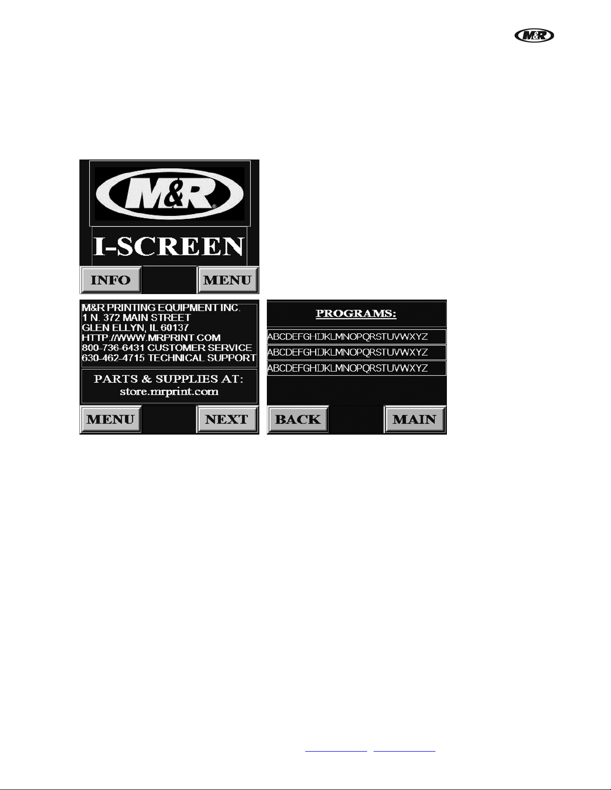
The Operator Interface touch screen is used to access and adjust all functions of the printer.
When electrical power is turned ON to the equipment, the MAIN message screen is displayed. In the lower right is
the MENU button and in the lower left is the INFO button. The INFO menu contains information on how to contact
M&R Printing Equipment. Press the NEXT button for program information. Press the MENU button to display the
MENU screen.
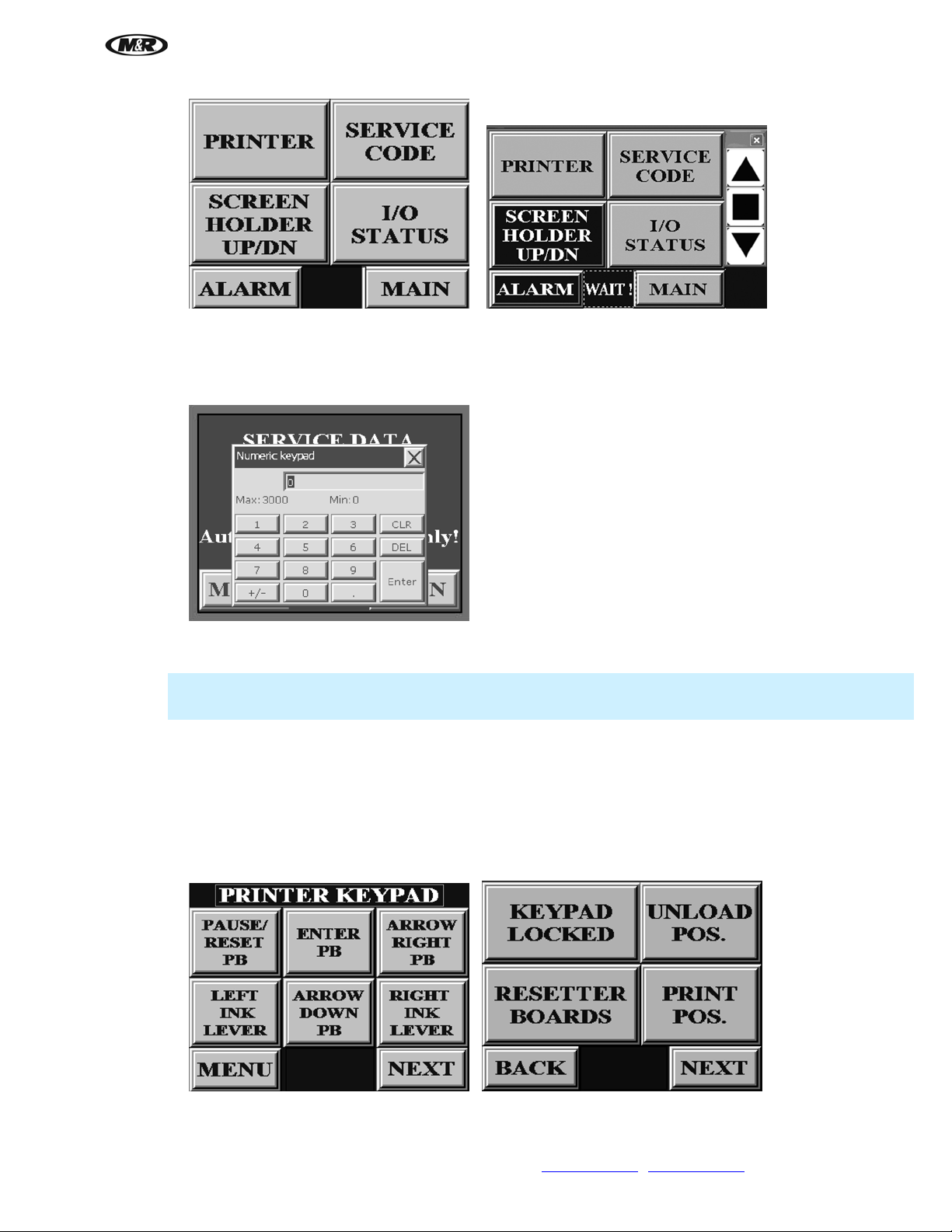
Menu Screen
The MENU screen is used to access all menus used to adjust unit functions or to display diagnostic and test data.
The MENU screen is also used to access the ALARM menu which displays the cause of alarm conditions.
If an ALARM condition is detected, Alarm flashes at the bottom of the display screen. Press ALARM to display
the cause of the alarm or error.
The menus on the MENU screen are PRINTER, SERVICE CODE, SCREEN HOLDER UP/DN, I/O STATUS,
ALARM, and MAIN.
The alarm WAIT! flashes when the screen holder is moving up or down and when printing. Alarm messages
override the WAIT message.
To return to the MAIN screen, press the MAIN button.
20 M&R Companies 1N 372 Main St. Glen Ellyn, IL 60137 USA
Tel: +630-858-6101 Fax: +630-858-6134 www.mrprint.com
| store.mrprint.com
Page 21
i-Screen™
V.081210
Keypad
A keypad is used to enter data. When a data entry cell requiring data is pressed; a numeric keypad displays.
Enter the value and press Enter.
Printer Control Panel Keypad
Note: Printer Control Panel Keypad buttons are locked to prevent sending unintentional commands to the
printer.
To access the PRINTER KEYPAD, use the SERVICE CODE menu. From the SERVICE DATA screen, press the
data entry cell; a keypad displays. Enter the password 248, then press Enter. The PRINTER KEYPAD displays.
Press PAUSE/RESET PB, ENTER PB, ARROW RIGHT PB or ARROW DOWN PB. The PRINTER KEYPAD
screen needs to be unlocked to access any other buttons on the Printer Control Panel. To unlock the PRINTER
KEYPAD screen, press NEXT. Press KEYPAD LOCKED to unlock Printer Control Panel. It changes to KEYPAD
UNLOCKED. It stays unlocked only for 60 seconds or until you move to another screen. Select RESETTER
BOARDS to reset ink chips and maintenance tank boards and use UNLOAD POS. and PRINT POS. to move
screen holder up and down.
M&R Companies 1N 372 Main St. Glen Ellyn, IL 60137 USA 21
Tel: +630-858-6101 Fax: +630-858-6134 www.mrprint.com
| store.mrprint.com
Page 22

i-Screen™
V.081210
Ink and Maint. Chips Reset
Select NEXT to access the INK CHIPS RESETS/MAINT. CHIPS RESETS screen. This screen also records the
Total Prints which is not resettable. To reset INK CHIPS RESETS or MAINT. CHIPS RESETS, press the data
entry cell to the right; a numeric keypad displays. Enter 0 and then press Enter. The counter is reset to 0.
Ink Drain Valve
Select NEXT to access the Ink valve screen. This screen determines the number of prints before the drain valve is
activated. The default is 150. It also shows the number of times the ink valve has been opened and the length of
the time the ink valve is open. The default is 3 seconds. The minimum time is 1 second and the maximum is 9.9
seconds. To reset a value, press the data entry cell to the right; a numeric keypad displays. Enter 0 and then
press Enter.
22 M&R Companies 1N 372 Main St. Glen Ellyn, IL 60137 USA
Tel: +630-858-6101 Fax: +630-858-6134 www.mrprint.com
| store.mrprint.com
Page 23
i-Screen™
V.081210
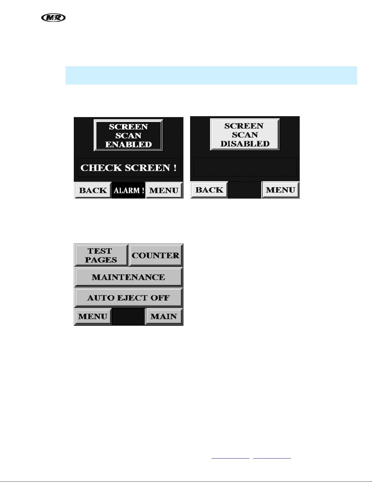
Screen Scan Enabled
Select NEXT to access the Screen Scan screen.
IMPORTANT: The Screen Scan should always be Enabled. If the Screen Scan is Disabled, damage to
the print head may occur.
Press the SCREEN SAN DISABLED button to enable screen scan.
If there is a problem during the scan, the screen returns to the Load Position. The ALARM message flashes and
the CHECK SCREEN message appears.
Printer Test pages, Counter, Maintenance and Auto Eject Off
Press the PRINTER button on the MENU screen to view the TEST PAGES, COUNTER, MAINTENANCE and
AUTO EJECT OFF screens. When AUTO EJECT OFF is selected, the screen remains down in a safe light
position until it is moved up to the unload position.
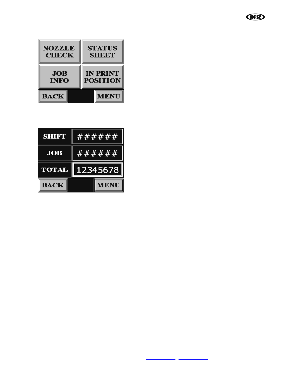
Press the TEST PAGES button to view the NOZZLE CHECK, STATUS SHEET, JOB INFO and IN PRINT
POSITION screens.
Nozzle Check - When selected, checks the print head for clogging and prints a test pattern that allows you to
check the nozzles for clogging. See Nozzle Check/Normal Cleaning as described in the Sch eduled Maintenance
Section.
Job Info and Status Sheet prints information about the printer.
M&R Companies 1N 372 Main St. Glen Ellyn, IL 60137 USA 23
Tel: +630-858-6101 Fax: +630-858-6134 www.mrprint.com
| store.mrprint.com
Page 24
i-Screen™
V.081210
In Print Position is illuminated when the screen frame holder is down in the print position.
Counter
The counter menu is accessed by pressing the COUNTER button. The counters menu contains thre e menus:
SHIFT, JOB, and TOTAL.
Shift Counter
Shift indicates the total number of printer cycles during a given production shift. To reset the Shift, press the data
entry cell to the right of Shift; a numeric keypad displays. Enter 0 and then press Enter. Shift is reset to 0.
Job Counter
Job indicates the total number of printer cycles for a given job. To reset the Job, press the data entry cell to the
right of Job; a numeric keypad displays. Enter 0 and then press Enter. Job is reset to 0.
Total Counter
Total displays the total number of printer cycles beginning from the initial date of installation of the equipment in
your production facility. Total is an indication of service life and cannot be changed.
24 M&R Companies 1N 372 Main St. Glen Ellyn, IL 60137 USA
Tel: +630-858-6101 Fax: +630-858-6134 www.mrprint.com
| store.mrprint.com
Page 25

i-Screen™
V.081210
Press the MAINTENANCE button to view the NORMAL CLEANING and POWER CLEANING screens.
Press NORMAL CLEANING to start a normal cleaning. If the ink on the screen is light after the printer has been
idle, run a Normal Cleaning. The Normal Cleaning is more than just cleaning the nozzle tips, it also makes sure
the dampers are full; thus ensuring good ink flow. The Normal Cleaning uses only a small amount of ink. Refer to
Normal Cleaning in the Scheduled Maintenance Section.
Press POWER CLEANING to start a power cleaning. The next screen displays the message Do you want to
proceed with Power Cleaning? Press the YES button and then the START POWER CLEANING button to start
the power cleaning cycle. Press the LEFT INK LEVER and RIGHT INK LEVER buttons on the Operator Interface
to eliminate messages on the Printer Control Panel screen. Power Cleaning is much more aggressive than
Normal Cleaning and consumes more ink. It is generally used as a last resort to clear clogged nozzles. Refer to
Power Cleaning in the Scheduled Maintenance Section.
I/O Status
Press the I/O STATUS button on the MENU screen to view the I/O Status screens.
The I/O STATUS menu provides a diagnostic tool for troubleshooting and isolation of operational errors. Press
NEXT to view additional input and output screens.
As switches are turned on/off, the indication confirms the correct operation of the particular switch or push button.
M&R Companies 1N 372 Main St. Glen Ellyn, IL 60137 USA 25
Tel: +630-858-6101 Fax: +630-858-6134 www.mrprint.com
| store.mrprint.com
Page 26
i-Screen™
V.081210
Alarms
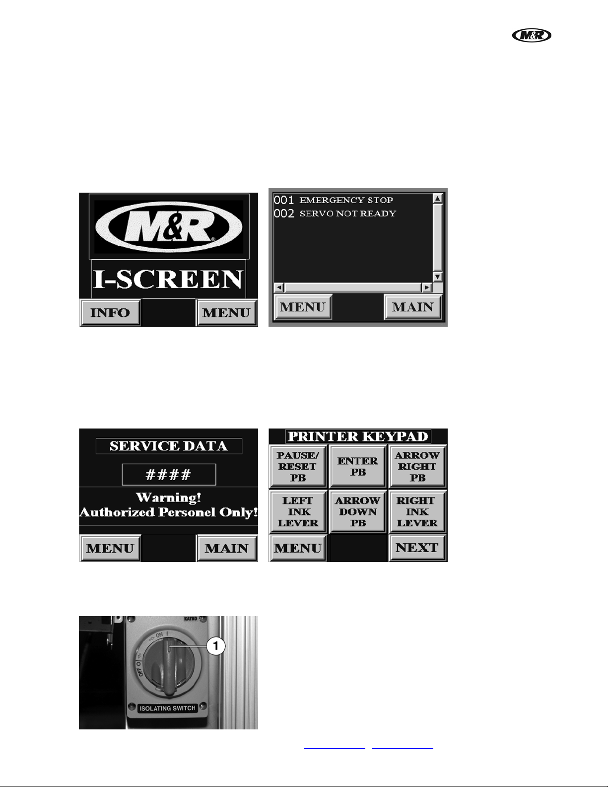
To access the ALARM screen, press the ALARM button on the MENU screen.
If an alarm condition is detected from the previous production run or production day, the ALARM indication is
flashing on the screen. This condition alerts the operator that an ALARM condition exists, and that operation of
the system is not possible.
To determine the cause of the ALARM condition, press the flashing ALARM button and the ALARM conditions
are displayed on the screen. For example, if the red Emergency Stop button has been activated, the ALARM
screen alerts the system operator by displaying Emergency stop.
Press the MENU button to return to the MENU screen.
Service Data
Press SERVICE CODE on the MENU screen to access the SERVICE DATA screen. Enter code 248 to access
the PRINTER KEYPAD screen and other screens. There is also a restricted area of the SERVICE DATA menu
that is only for the use of M&R Technical Representatives and should not be accessed or used by operators
unless instructed by M&R Technical Service personnel.
5.2 Start Up
1. To supply electrical power and air to the unit, turn ON/OFF switch (1) to the ON position.
26 M&R Companies 1N 372 Main St. Glen Ellyn, IL 60137 USA
Tel: +630-858-6101 Fax: +630-858-6134 www.mrprint.com
| store.mrprint.com
Page 27
i-Screen™
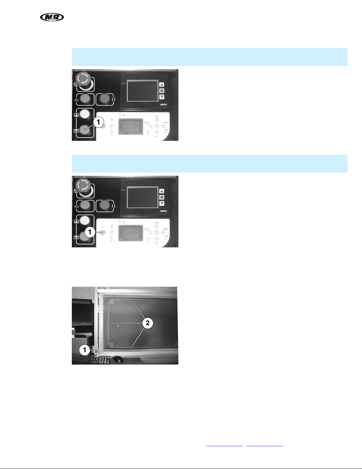
2. Depress foot pedal to lower upper frame holder. Press button (1) to move screen down to print position.
Note: There is a 7 second delay before the Print Position button (1) will work. The upper frame
holder must be in the down position before the screen frame holder will move down.
3. Turn on printer (1). The indicator above the button illuminates when the power is on.
Note: The frame holder assembly must be in the down position before the printer will complete the
start up sequence.
V.081210
5.3 Load Screen
1. Place screen against left side of the bottom screen fra me holder (1). Push screen firmly against screen
pusher (2) and hold in place.
M&R Companies 1N 372 Main St. Glen Ellyn, IL 60137 USA 27
Tel: +630-858-6101 Fax: +630-858-6134 www.mrprint.com
| store.mrprint.com
Page 28
i-Screen™
V.081210
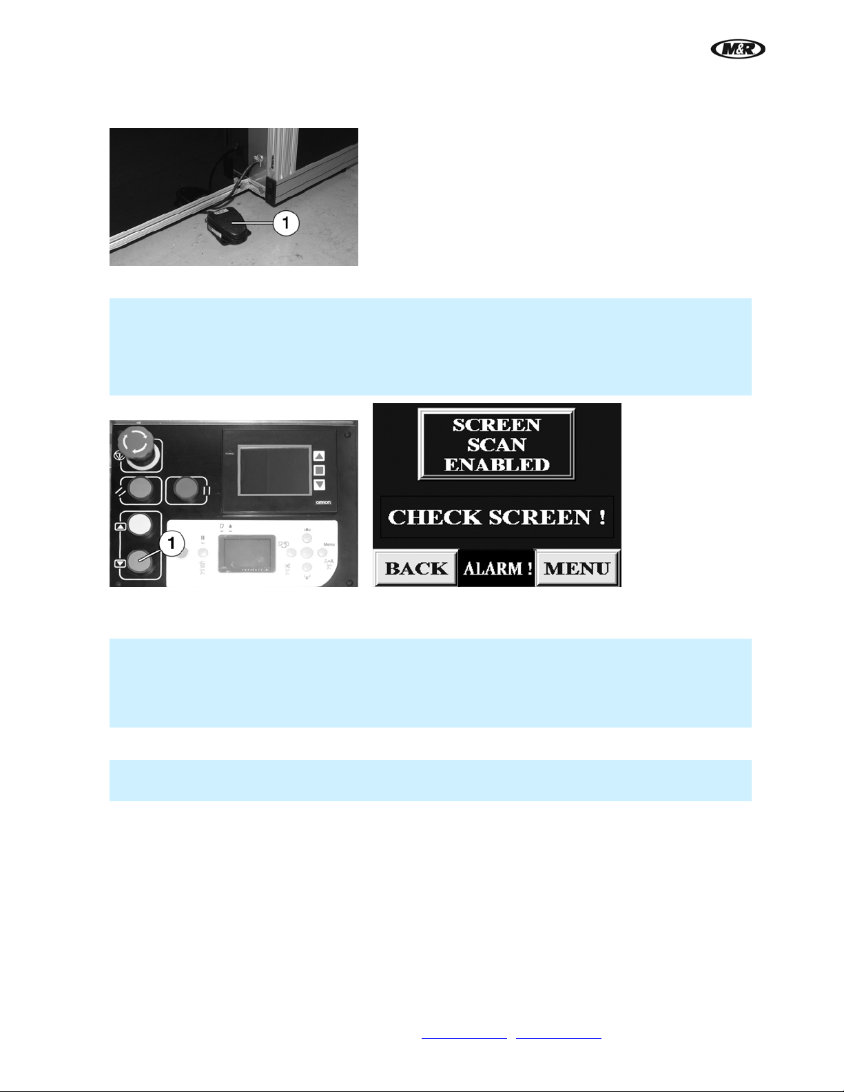
2. Depress and release the Foot Pedal (1). The top screen frame holder moves down and locks the
screen.
3. Press button (1) to move scre en down to print position.
Note: After pushing the Print Position button, the screen frame and screen is scanned to make sure
that there is clearance between the screen and the print head. If there is not adequate clearance, an
ALARM message appears and the screen frame and screen moves back up to the Load Position.
IMPORTANT: The Screen Scan should always be Enabled. If the Screen Scan is Disabled, damage
to the print head may occur.
5.4 Install i-Screen PPD File into Illustrator
IMPORTANT: Art files created using Adobe Illustrator must be processed for the i-Screen using a
supplied PPD file; this file essentially creates a fictitious printer that will process art files to a Post
Script file compatible with the i-Block RIP. The Following steps detail installing the PPD on art
department workstations. This applies to Adobe Illustrator CS1 - CS3. Illustrations are from CS3 on a
Macintosh computer.
1. Download the PPD file to the computers desktop, and then open Adobe Illustrator.
IMPORTANT: The PPD file should remain on the desktop. If the PPD file is moved, you will have to
go through this procedure again to select the PPD file from the new location.
28 M&R Companies 1N 372 Main St. Glen Ellyn, IL 60137 USA
Tel: +630-858-6101 Fax: +630-858-6134 www.mrprint.com
| store.mrprint.com
Page 29
i-Screen™
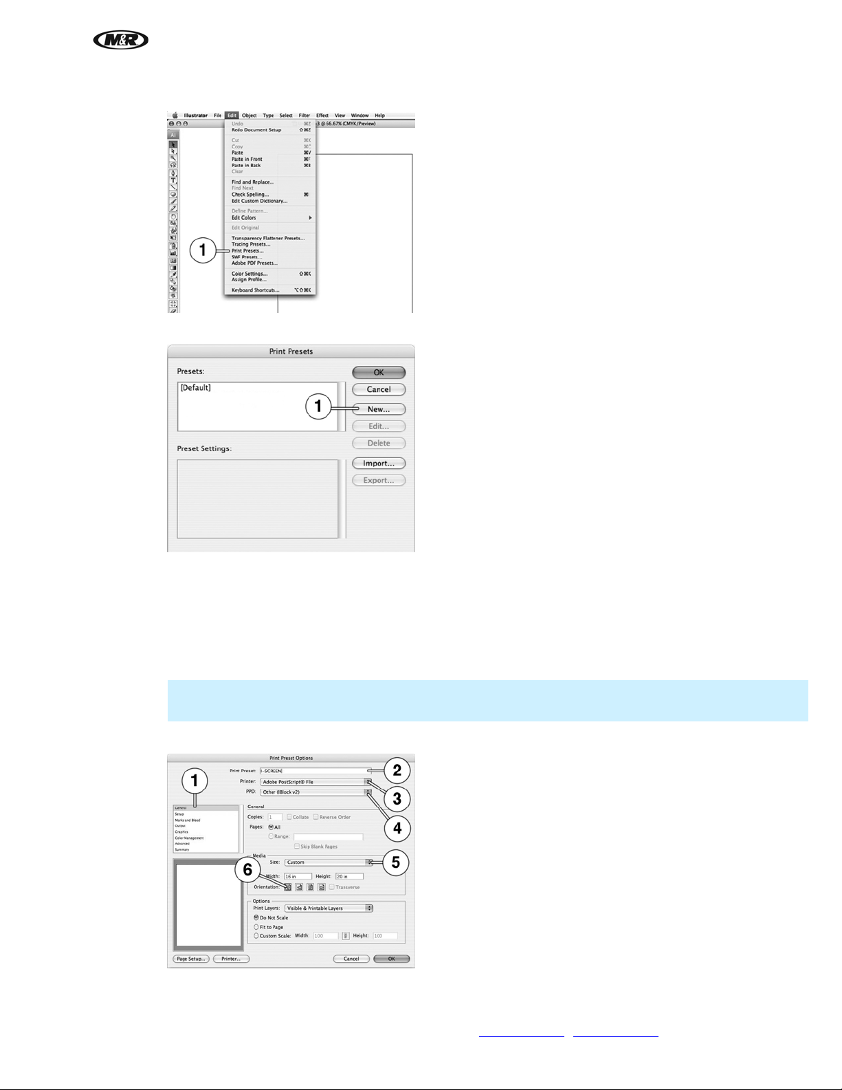
2. Select Print Presets (1) from the Edit menu.
3. Select New (1).
V.081210
4. Select General (1) from the menu on the Print Preset Options screen:
On the Print Preset (2) window, type in i-Screen.
For Printer choose Adobe PostScript® File (3).
For PPD (4), find and select the i-Block.ppd file AI_SEP v2.PPD that was downloaded to the desktop.
Size should be Custom (5).
Note: When selecting Custom in the Media Size window, the Print Preset (2) will change to Custom,
this is normal.
The default Orientation should be Portrait (6).
M&R Companies 1N 372 Main St. Glen Ellyn, IL 60137 USA 29
Tel: +630-858-6101 Fax: +630-858-6134 www.mrprint.com
| store.mrprint.com
Page 30

i-Screen™
V.081210
5. Select Setup (1) from the menu on the Print Preset Options screen:
For Crop Artwork to select Artboard (2).
The X and Y Placement (3) should be 0 in. by 0 in.
For Tiling (4) select Single Full Page.
6. Select Output (1 ) from the menu on the Print Preset Options screen:
For Mode (2) select Separations (Host-Based).
For Emulsion (3) select Up (Right Reading).
For Image (4) select Positive.
Note: Make sure Convert All Spot Colors to Process and Overprint (5) are NOT selected.
30 M&R Companies 1N 372 Main St. Glen Ellyn, IL 60137 USA
Tel: +630-858-6101 Fax: +630-858-6134 www.mrprint.com
| store.mrprint.com
Page 31

i-Screen™
7. Select Graphics (1) from the menu on the Print Preset Options screen:
For Fonts Download (2) select Subset.
For PostScript® (3) select LanguageLevel3.
For Data Format (4) select ASCII.
8. Select Color Management (1) from the menu on the Print Preset Options screen:
For Color Handling (2) select Let Illustrator determine colors.
V.081210
For Printer Profile (3) select U.S. Web Coated (SWOP) v2.
For Rendering Intent (4) select Relative Colorimetric.
M&R Companies 1N 372 Main St. Glen Ellyn, IL 60137 USA 31
Tel: +630-858-6101 Fax: +630-858-6134 www.mrprint.com
| store.mrprint.com
Page 32
i-Screen™
V.081210
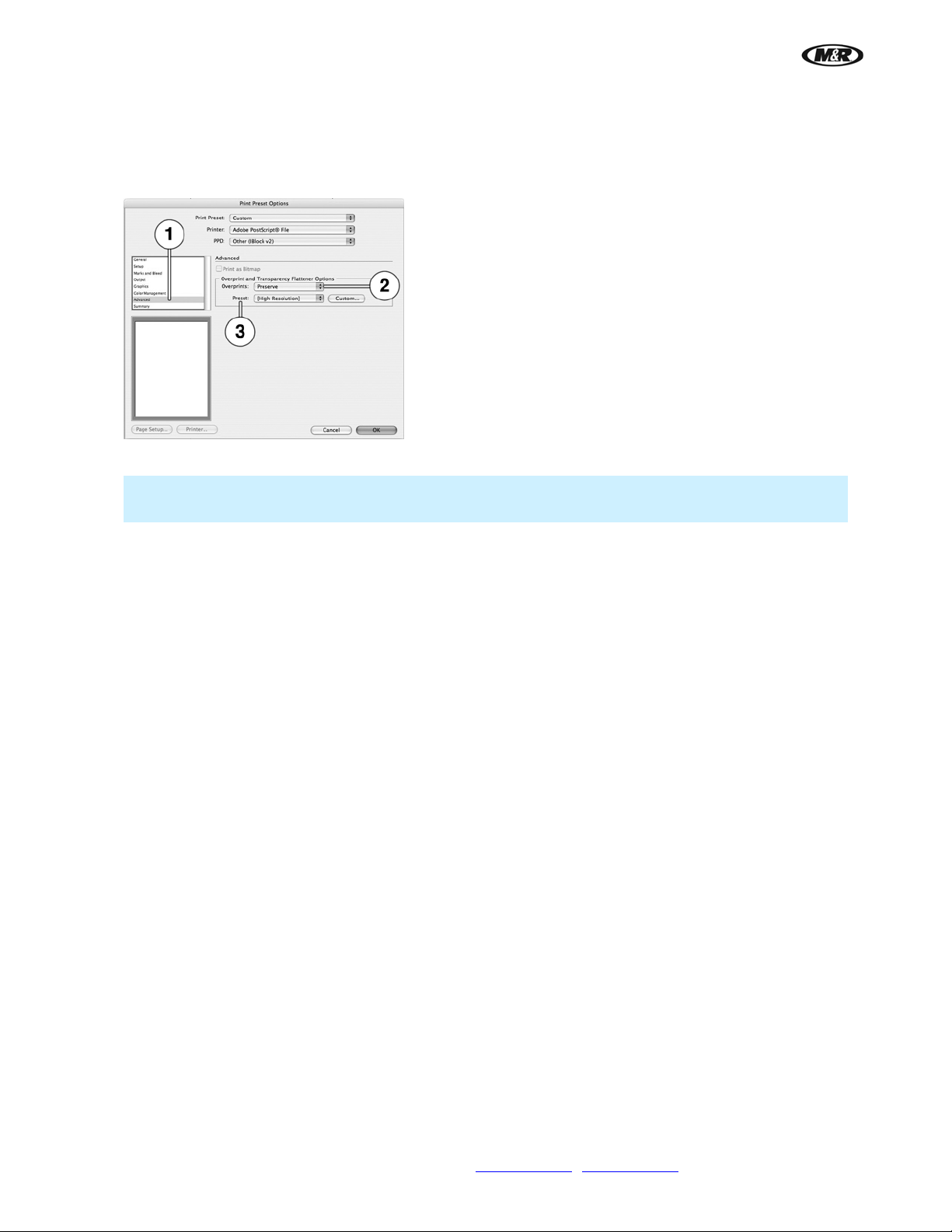
9. Select Advanced (1 ) from the menu on the Print Preset Options screen:
For Overprints (2) select Preserve.
For Preset (3) select (High Resolution).
10. Click Save or OK to save the Print Preset Options.
IMPORTANT: The PPD file should remain on the desktop. If the PPD file is moved, you will have to
go through this procedure again to select the PPD file from the new location.
32 M&R Companies 1N 372 Main St. Glen Ellyn, IL 60137 USA
Tel: +630-858-6101 Fax: +630-858-6134 www.mrprint.com
| store.mrprint.com
Page 33
i-Screen™
5.5 Opening Adobe Illustrator Files for Separation
IMPORTANT: Illustrator files must be created using spot colors.
Note: These steps are required to prepare Adobe Illustrator file to print as PostScript® files on the iScreen. Examples are shown for Adobe Illustrator CS3 on a MacIntosh computer; the steps should be
similar in older and newer versions.
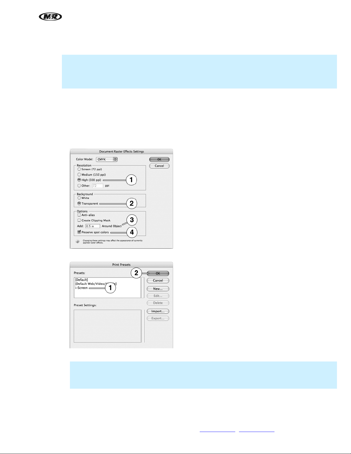
1. After the PPD file is installed on the desktop of the art department computer, use the Effect/Document
Raster Effects Settings menu and the following settings:
Resolution, High (300 ppi) (1).
Background, Transparent (2).
Options, Add 0.5 in. Around Object (3).
Check Preserve spot colors when possible (4).
V.081210
2. Select i-Screen Edit/Print Presets file (1) just created and cli ck OK (2).
3. Use File/Open to select an d the image you want to print.
Note: When importing art files, download them to the computer rather then opening them from a flash
drive, CD-ROM or network drive.
Note: Check the following settings to make sure that they are correct.
4. In General (1) on the Print screen:
Print Preset (2) should be Custom.
Printer should be Adobe PostScript
M&R Companies 1N 372 Main St. Glen Ellyn, IL 60137 USA 33
Tel: +630-858-6101 Fax: +630-858-6134 www.mrprint.com
®
File (3).
| store.mrprint.com
Page 34

i-Screen™
V.081210
PPD, should be the i-Block.ppd file (4).
Size should be Custom (5).
The default Orientation should be Portrait (6).
5. In Setup (1) on the Print screen:
Crop Artwork to should be Artboard (2).
The X and Y Placement (3) should be 0 in. by 0 in.
Tiling (4) should be Single Full Page.
34 M&R Companies 1N 372 Main St. Glen Ellyn, IL 60137 USA
Tel: +630-858-6101 Fax: +630-858-6134 www.mrprint.com
| store.mrprint.com
Page 35
i-Screen™
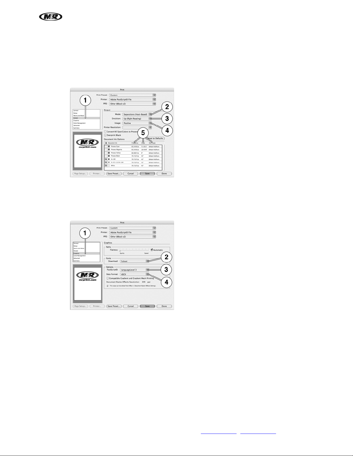
6. In Output (1) on the Print screen:
Mode (2) should be Separations (Host-Based).
Emulsion (3) should be Up (Right Reading).
Image (4) should be Positive.
Double click to select and set halftone parameters; Frequency, Angle and Dot Shape (5).
7. In Graphics (1) on the Print screen:
V.081210
Fonts Download (2) should be Subset.
®
PostScript
(3) should be LanguageLevel3.
Data Format (4) should be ASCII.
M&R Companies 1N 372 Main St. Glen Ellyn, IL 60137 USA 35
Tel: +630-858-6101 Fax: +630-858-6134 www.mrprint.com
| store.mrprint.com
Page 36
i-Screen™
V.081210
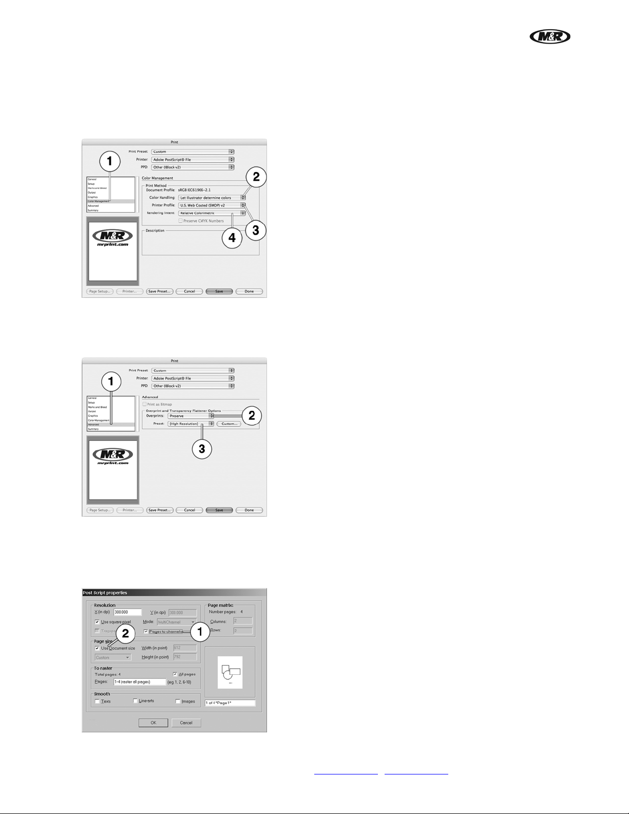
8. In Color Management (1) on the Print screen:
Color Handling (2) should be Let Illustrator determine colors.
Printer Profile (3) should be U.S. Web Coated (SWOP).
Rendering Intent (4) should be Relative Colorimetric.
9. In Advanced (1) on the Print screen:
Overprints (2) should be Preserved.
Preset (3) should be (High Resolution).
10. Use Post Script Properties to select the following:
Use Pages to channels (1) to get the separations as channels, Mode is grayed out and is
MultiChannel is selected.
For Page size, use Document size (2) for the separations.
36 M&R Companies 1N 372 Main St. Glen Ellyn, IL 60137 USA
Tel: +630-858-6101 Fax: +630-858-6134 www.mrprint.com
| store.mrprint.com
Page 37
i-Screen™
V.081210
5.6 Printing
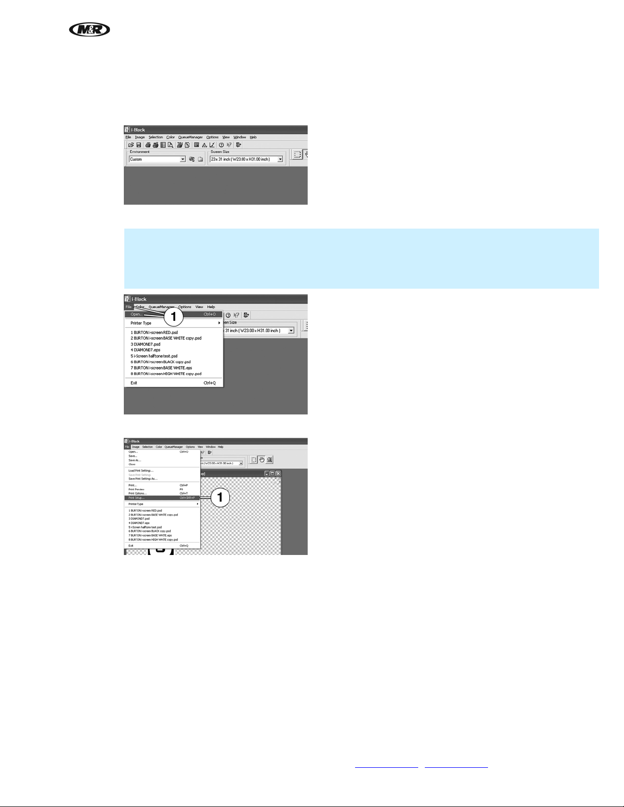
From the computer desktop, double click on the i-Block icon to open the i-Block software. This opens the main iBlock workspace.
1. Use File/Open (1) to select and the imag e you want to print.
IMPORTANT: Adobe Illustrator files must be prepared using spot colors to print as PostScript® files on
the i-Screen. Refer to Preparing Adobe Illustrator Files for Separation in this manual.
Note: When importing art files, download them to the computer rather then opening them from a flash
drive, CD-ROM or network drive.
2. When file is open, sel ect File/Print Setup (1).
M&R Companies 1N 372 Main St. Glen Ellyn, IL 60137 USA 37
Tel: +630-858-6101 Fax: +630-858-6134 www.mrprint.com
| store.mrprint.com
Page 38
i-Screen™
V.081210
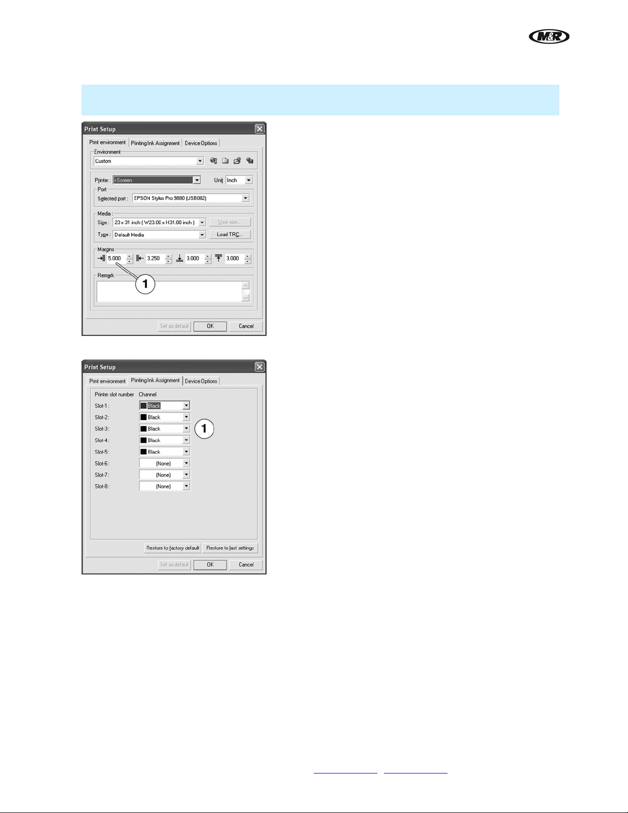
3. From Print Setup sele ct the Print Environment tab. Enter the Margins (1).
Note: The left margin is the distance from the top on the screen to the image. The default places the
image 3.25" from the top edge of the screen. This is the same for each color screen.
4. From the Print Setup/Printing Ink Assignment tab, select the number of channels (1) to deliver ink.
38 M&R Companies 1N 372 Main St. Glen Ellyn, IL 60137 USA
Tel: +630-858-6101 Fax: +630-858-6134 www.mrprint.com
| store.mrprint.com
Page 39
i-Screen™
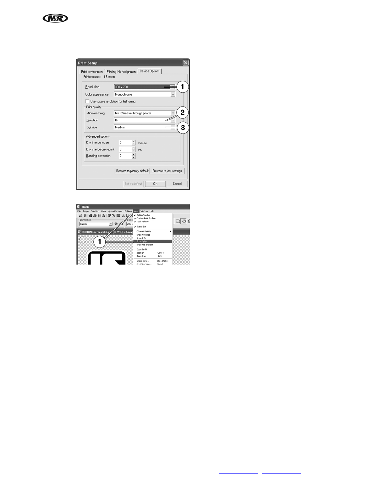
5. From the Print Setup/Device Options tab, select the Resolution (1) (360 x 360), (360 x 720), (720 x
360) (720 x 720), Direction (2) Bi or Uni and Dot Size (3), Small, Medium or Large.
6. To position or size the image or add crop or registration marks, select View/Show QRip (1).
V.081210
M&R Companies 1N 372 Main St. Glen Ellyn, IL 60137 USA 39
Tel: +630-858-6101 Fax: +630-858-6134 www.mrprint.com
| store.mrprint.com
Page 40

i-Screen™
V.081210
7. Change the size, image p osition and add crop or registration marks in the QRip (Print Options)
window.
The QRip window handles size scaling and image positioning. Custom must be selected (1) in order to
make size adjustments. Selecting the lock function (2) allows images to be scaled to proportion when
adjusting either the width or height. Scaling can be performed by either typing in a numeric value or by
using the up/down arrows to the right of each box.
Use Position to position the image on the screen. The default is Top Center which places the image
3.25” from the top edge of the screen. Click the Top Center menu arrow (3) or select Custo m to
activate the X and Y position windows.
The X-axis adjusts the image position right to left on the screen. Zero X value is the center of the screen.
Entering a positive number moves the image to the left on the screen, entering a negative number
moves the image to the right.
The Y-axis adjusts image position height on the screen. Entering a positive number in the Y window
moves the Image down on the screen. The default image height is always 3.25” down from the top of the
screen. The image may only be moved down from this point, by either typing in a positive number or
using the up arrow to make changes.
Select Draw Markings (4) to print crop marks on the screen. Select Print registration marks (5) to
print registration marks on the screen.
40 M&R Companies 1N 372 Main St. Glen Ellyn, IL 60137 USA
Tel: +630-858-6101 Fax: +630-858-6134 www.mrprint.com
| store.mrprint.com
Page 41
i-Screen™
5.7 Unload Screen
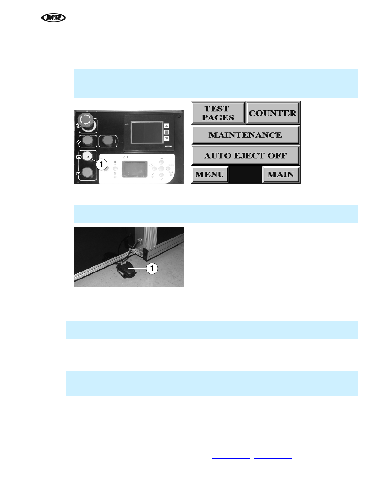
1. When printing has finished, press yellow button (1) to move screen up to the unload position.
Note: There is a pause after printing while the print head is safely parked before the screen can be
moved up. The ALARM button flashes during the pause.
If AUTO EJECT ON is selected, the screen automatically moves up to the unload position.
2. Depress and release the Foot Pedal (1). The top screen frame holder moves up and unlocks the screen.
Remove screen.
V.081210
IMPORTANT: Hold the screen to prevent the screen from falling forward and possibly damaging the
screen.
5.8 Shutdown
Daily Shutdown
IMPORTANT: To correctly seat the head on the capping station, DO NOT use the main power switch,
use the Power button on the printer control panel to turn off the printer.
Turn off printer using the Power button on the Printer Control Panel. The Printer Control Panel screen displays
POWER OFF and after the print head is correctly seated the screen goes dark.
Long Term Shutdown
IMPORTANT: If printer is idle for more than 14 days, certain precautions must be taken. Refer to
Scheduled Maintenance Section. If these procedures are not followed, ink may dry on print head and it
may have to be replaced.
Flush ink from system using the cleaning solution. Refer to Flushing Ink From System in the Scheduled
Maintenance Section.
M&R Companies 1N 372 Main St. Glen Ellyn, IL 60137 USA 41
Tel: +630-858-6101 Fax: +630-858-6134 www.mrprint.com
| store.mrprint.com
Page 42
i-Screen™
V.081210
6. Troubleshooting
General Guide
The following information is provided as a guide for troubleshooting. If you have any questions regarding the
installation, operation, or preventive maintenance procedures for this equipment, contact The M&R Companies
Service Department. Anyone using this troubleshooting guide should have a working knowledge of electrical
power and the control systems on this equipment.
Schematic
Electrical schematics are located in the back of this manual.
IMPORTANT: This unit must receive adequate electrical power to perform properly. Make sure the
electrical power lines to the equipment are on.
6.1 Printer Control Panel
Problem
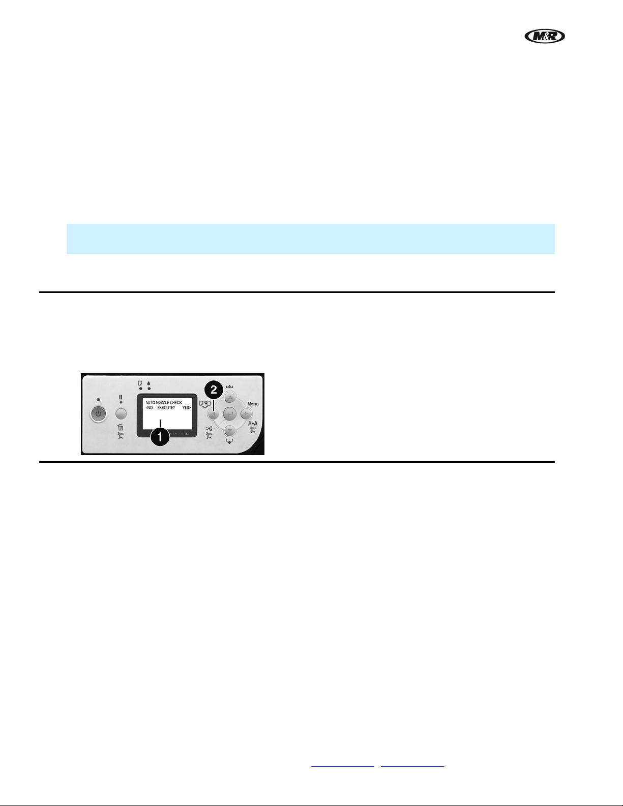
Printer Control Panel screen (1) displays AUTO NOZZLE CHECK, EXECUTE?
Solution
Unlock Printer Control Panel keypad (Refer to Operator Interface Section of this manual) and
use the Arrow Left button (2) to select <NO.
Problem
Printer Control Panel screen displays COVER OPEN, CLOSE COVER.
Solution
Lower Upper Frame Holder. Move Screen holder down to print position.
42 M&R Companies 1N 372 Main St. Glen Ellyn, IL 60137 USA
Tel: +630-858-6101 Fax: +630-858-6134 www.mrprint.com
| store.mrprint.com
Page 43

i-Screen™
7. Scheduled Maintenance
Benefits
Properly maintained equipment operates more efficiently, reduces operating costs, and lasts longer. A properly
managed preventive maintenance program can minimize downtime.
Preparation
An effective preventive maintenance program includes:
proper selection, handling, and application of lubricants
stocking high-quality replacement parts
general cleaning and appearance of equipment
creation of a preventive maintenance history for each piece of equipment
Preventive maintenance documentation can be an invaluable resource.
As Required
V.081210
Power Cleaning
IMPORTANT: Always do a Nozzle Check and Normal Cleaning bef ore running a Power Cleaning.
1. From the MENU scree n, press the PRINTER button.
2. Press the MAINTENANCE button to view the CLEANING menu. Press the POWER CLEANING button.
IMPORTANT: The screen holder must be down in the Print Position to do a power cleaning.
M&R Companies 1N 372 Main St. Glen Ellyn, IL 60137 USA 43
Tel: +630-858-6101 Fax: +630-858-6134 www.mrprint.com
| store.mrprint.com
Page 44

i-Screen™
V.081210
3. The next screen will prompt you with Do you want to proceed with Power Cleaning? Select YES or
NO. NO returns you to the previous menu.
Note: A Power Cleaning Cycle uses much more ink than a standard head cleaning and should only be
used on the initial start up or after completing several normal head cleanings.
4. Press the YES button and then the START POWE R CLEANING button to start the power cleaning
cycle. Press the LEFT INK LEVER and RIGHT INK LEVER buttons on the Operator Interface display to
eliminate messages as they appear on the Printer Control Panel screen.
Empty Waste Bin
The waste bin stores ink from print head cleaning. When the bin is full, the message WASTE BIN FULL appears
on the Operator Interface screen.
1. Make sure th e printer is not printing or performing any other operations.
2. Open door (1 ). Use rubber gloves and have a rag ready to absorb any excess ink from ink tubes.
Loosen handle (2) and slide handle and bracket up approximately 2 inches so that hose s cl ear the top of
the container. Place rag under ink tubes. Carefully pull out waste bin (3). Avoid tipping the waste bin
over as ink may run out of the waste bin.
3. Empty waste bin and reinstall wa ste bin and ink tubes.
44 M&R Companies 1N 372 Main St. Glen Ellyn, IL 60137 USA
Tel: +630-858-6101 Fax: +630-858-6134 www.mrprint.com
| store.mrprint.com
Page 45
i-Screen™
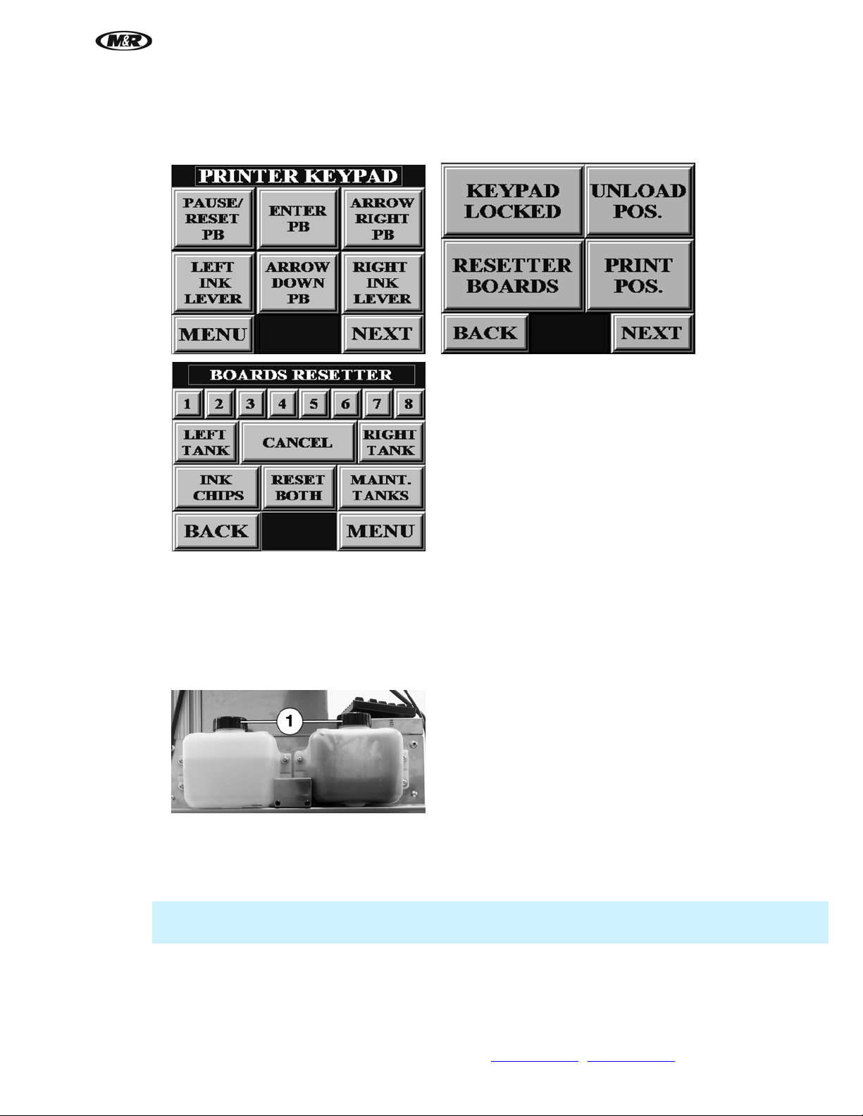
4. To access PRINTER KEYPAD, use the SERVICE CODE menu. From the SERVICE DATA menu,
press the data entry cell; a keypad displays. Enter the password 248, then press ENTER. On the
PRINTER KEYPAD press NEXT. Press RESETTER BOARDS to display the BOARDS RESETTER
screen. Press MAINT. TANKS to reset the maintenance tank.
V.081210
Fill Ink and Cleaning Solution Tanks
When the ink tank is empty, the message INK TANK EMPTY appears on the Operator Interface screen. When
the cleaning tank is empty, the message CLEANING TANK EMPTY appears on the Operator Interface screen.
When the tank is filled, the message is automatically eliminated.
1. When filling ink tank, make sure cleani ng fluid valve is closed (at 90 degrees to cleaning fluid line).
2. Remove cap (1) a nd fill right ink tank with ink or left cleaning tank with cleaning fluid. Replace cap.
Clean Operator Interface Display Screen
If the screen surface should require cleaning, clean surface before turning on power. Use a clean, lint-free wiper
or paper towel lightly moistened with clear clean water and gently wipe the surface of the screen.
Note: Do not use solvents such as acetone, MEK or mineral spirits to clean the screen surface. These
solvents will attack the surface of the screen leaving a dull finish making the display difficult to read.
M&R Companies 1N 372 Main St. Glen Ellyn, IL 60137 USA 45
Tel: +630-858-6101 Fax: +630-858-6134 www.mrprint.com
| store.mrprint.com
Page 46
i-Screen™
V.081210
Flushing Ink From System
IMPORTANT: If printer is idle for more than 14 days, certain precautions must be taken. If these
procedures are not followed, ink may dry on print head and it may have to be replaced.
IMPORTANT: Before flushing ink from system, make sure waste bin is not almost full or added ink
may cause it to overflow.
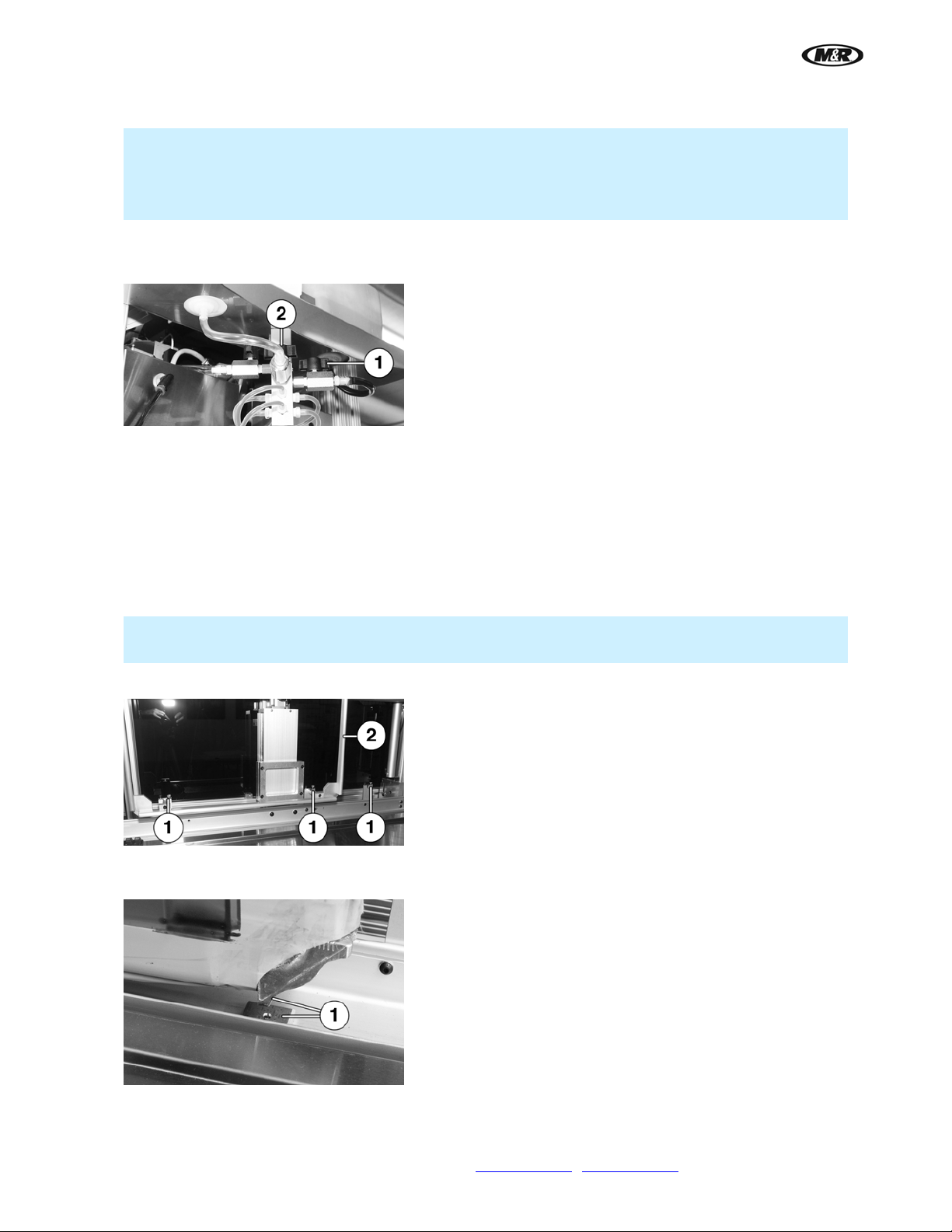
1. Close ink valve (1). Turn valve handle so that it is 90 degrees to the ink line.
2. Open cleaning fluid valve (2) to the cleaning fluid tank so that it is parallel with the cleaning fluid line.
3. Perform two Power Cleani ngs, refer to Power Cleaning in the Scheduled Maintenance Section.
4. Check ink lines. If ink is still in the lines, do another Power Cleaning.
Change Screen Pusher
i-Screen is adjusted for the screen pusher installed when the i-Screen is shipped. To change to a different size
screen pusher:
1. Loosen thumb scre ws (1) until latch can be rotated.
2. Lift and remove screen pusher (2) and install the new size screen pusher.
IMPORTANT: The size, stamped on the pusher frame, should always be mounted in the upper left-
hand corner.
3. Rotate latch and tighten thumb screws (1).
4. When using screens with Newman Roller Frames, the bottom right stop block must be positioned under
the corner of the frame (1).
5. To move the block, first push the Emergency Stop button.
6. Remove left rear cover.
46 M&R Companies 1N 372 Main St. Glen Ellyn, IL 60137 USA
Tel: +630-858-6101 Fax: +630-858-6134 www.mrprint.com
| store.mrprint.com
Page 47

i-Screen™
7. Loosen thumb scre w (1) and move locating block until it is positioned under the corner of the frame (see
step 4). Tighten thumb screw. Replace cover. Release Emergency Stop button.
V.081210
Daily
Nozzle Check/Normal Cleaning
1. From the MENU scree n, press the PRINTER button. Press TEST PAGES to view the NOZZLE CHECK
menu.
2. Apply Pallet Peel to the test panel. Install the test panel (1) in the front of the screen holder.
Note: It may be necessary to remove a large screen pusher frame so the test panel fits in the screen
frame holder.
3. Press the NOZZLE CHECK button. After the no zzle check is complete, examine the Nozzle Check
pattern to make sure it has no gaps or broken lines. If there are gaps on the Nozzle Check pattern, do a
Normal Cleaning.
IMPORTANT: The screen holder must be in the Print Position to do a normal cleaning.
M&R Companies 1N 372 Main St. Glen Ellyn, IL 60137 USA 47
Tel: +630-858-6101 Fax: +630-858-6134 www.mrprint.com
| store.mrprint.com
Page 48

i-Screen™
V.081210
Note: If the nozzles do not clear after 2-3 Normal Cleaning cycles, run a Power Cleaning Cycle as
described in the Scheduled Maintenance Section.
Normal Cleaning
1. From the MENU scree n, press the PRINTER button.
2. Press MAINTENANCE to view the CLEANING menu. Press the NORMAL CLEANING button to start a
normal cleaning.
IMPORTANT: The screen holder must be down in the Print Position to do a normal cleaning.
48 M&R Companies 1N 372 Main St. Glen Ellyn, IL 60137 USA
Tel: +630-858-6101 Fax: +630-858-6134 www.mrprint.com
| store.mrprint.com
Page 49

i-Screen™
Clean Capping Station and Wiper
IMPORTANT: To prevent ink from drying on print head, this must be part of the shutdown procedure
whenever printer will be idle.
1. Turn printer off.
2. Open right front cover.
3. Push in on blue latch (1) and move pri nt head (to the left) away from capping station.
4. Using syringe, place 1-2 cc of i-Clean solution on capping station (2).
5. Use cleaning swab to sp read solution across top of capping station (2). Use a cleaning swab dipped in i-
Clean solution to clean wiper (3). Clean and inspect gasket around the edge of the capping station and
remove any ink buildup from edge of capping station (2).
6. Move print head back into position over the capping station.
V.081210
Drain Air Filter Moisture Trap
Press and hold the orange button (1) on the bottom of the filter until no moisture is present in the air.
Note: If water or excessive moisture is in the reservoir, remove water/moisture from reservoir and inspect
the chiller and compressor for proper operation.
Reset Boards
The i-Screen program automatically resets the ink chips and maintenan ce tank boards each time the main power
is turned on.
IMPORTANT: If the main power is not turned on daily, the Ink Chips and Maintenance Tank Boards must
be reset daily to avoid problems with the i-Screen. When the main power is turned on, the chips are
automatically reset.
To access PRINTER KEYPAD, use the SERVICE CODE menu. From the SERVICE DATA menu, press the data
entry cell; a keypad displays. Enter the password 248, then press ENTER. On the PRINTER KEYPAD press
NEXT. Press RESETTER BOARDS to display the BOARDS RESETTER screen. Press RESET BOTH to reset
the ink chips and maintenance tank boards. The Printer Control Panel screen displays messages while resetting
the boards and then displays READY.
M&R Companies 1N 372 Main St. Glen Ellyn, IL 60137 USA 49
Tel: +630-858-6101 Fax: +630-858-6134 www.mrprint.com
| store.mrprint.com
Page 50
i-Screen™
V.081210
Note: Screen holder must be down in print position before boards can be reset.
Weekly
WARNING: To prevent possible injury to personnel and/or damage to the equipment, lock out and tag the
electrical service and compressed air supply to the equipment
Clean Print Rails
Items required:
1 - Isopropyl Alcohol
1 - Towel
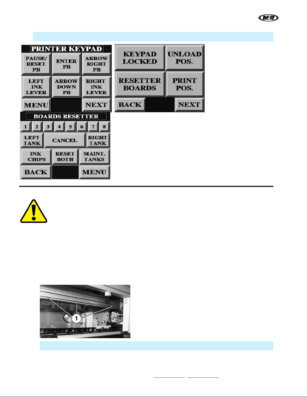
1. Open door. Using a towel and a small amount of alcohol, clean excess ink from top of front print rail (1).
IMPORTANT: You must clean both sides of the print rail.
50 M&R Companies 1N 372 Main St. Glen Ellyn, IL 60137 USA
Tel: +630-858-6101 Fax: +630-858-6134 www.mrprint.com
| store.mrprint.com
Page 51

i-Screen™
2. Remove back covers. Clean excess ink from top of back print rail (2).
3. Replace covers.
Monthly
WARNING: To prevent possible injury to personnel and/or damage to the equipment, lock out and tag the
electrical service and compressed air supply to the equipment.
Replace Print Head Excessive Ink Sponge
V.081210
Items required:
1 - Replacement Filter (M & R Part No. 9D01284)
1 - Towel
1. Turn printer off.
2. Open right front cover. Push in on blue l atch (1) and move print head (to the left) away from capping
station.
3. Remove the left rear cover. Using rubber gloves, remove sponge insert (2) from holder. Clean holder
and replace sponge insert (2).
IMPORTANT: Be careful not to touch head (3) when replacing sponge.
M&R Companies 1N 372 Main St. Glen Ellyn, IL 60137 USA 51
Tel: +630-858-6101 Fax: +630-858-6134 www.mrprint.com
| store.mrprint.com
Page 52
i-Screen™
V.081210
Every Six Months
WARNING: To prevent possible injury to personnel and/or damage to the equipment, lock out and tag the
electrical service and compressed air supply to the equipment.
Lubricate Linear Bearings
Items required:
1 - White Lithium Grease (M&R Part No. 7018017)
1 - Standard pump action grease gun
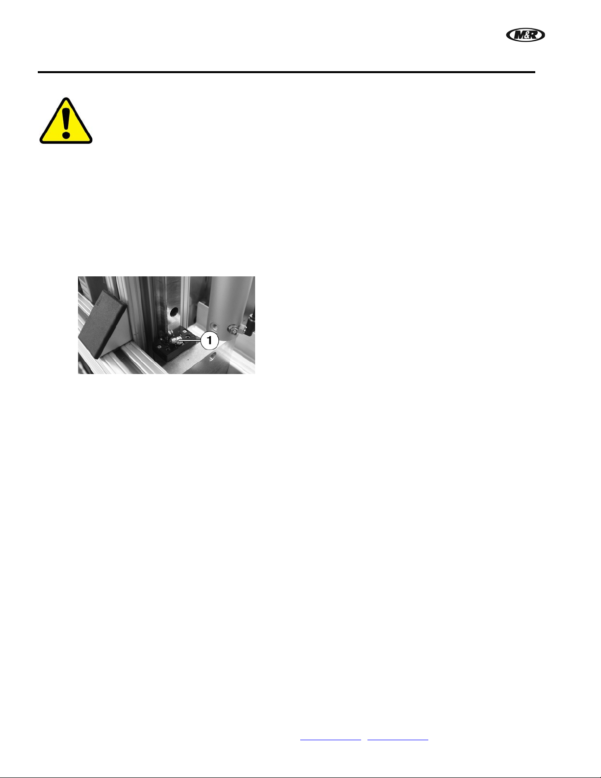
Using a standard pump action grease gun, apply 3 or 4 applications of grease to the grease fittings (1) (top and
bottom and both sides) of the screen frame.
52 M&R Companies 1N 372 Main St. Glen Ellyn, IL 60137 USA
Tel: +630-858-6101 Fax: +630-858-6134 www.mrprint.com
| store.mrprint.com
Page 53

i-Screen™
Every Two Years
WARNING: To prevent possible injury to personnel and/or damage to the equipment, lock out and tag the
electrical service and compressed air supply to the equipment.
Replace Air Filter Element and Reservoir Seal
Items required:
1 - Filter Element (M&R Part No. 2020036-A)
1 - Bowl Seal (M&R Part No. 2020036-B)
1 - 10 wt. Non-Detergent Oil (M&R Part No. 7017000)
V.081210
1. Press and hold the oran ge button (1) on the bottom of the filter to bleed off any residual air which may
remain in the system.
2. Remove the Moisture Trap by pushing down the black locking latch (2) and turn 1/8 of a turn
counterclockwise. Align the single line on the upper assembly with the double line on the Reservoir (3)
and pull straight down and away from the Filter/Regulator Assembly.
3. Remove Bowl Seal (4) from Reservoi r and replace with new Seal. Lightly lubricate the outside surface
of the new seal with 10 wt. Non-Detergent Oil.
4. Remove the Baffle (5) by turning to the left (counterclockwise).
5. Install new Filter Element (6) and repl ace Baffle (5). Replace Reservoir (3). Firmly push Reservoir up
into the Filter/Regulator Assembly and turn 1/8 turn to lock into place.
Note: The level sight glass should be facing towards the front of the assembly.
M&R Companies 1N 372 Main St. Glen Ellyn, IL 60137 USA 53
Tel: +630-858-6101 Fax: +630-858-6134 www.mrprint.com
| store.mrprint.com
Page 54
i-Screen™
V.081210
Every Three Years
WARNING: To prevent possible injury to personnel and/or damage to the equipment, lock out and tag the
electrical service and compressed air supply to the equipment.
Replace Servo Amplifier Battery
Items required:
1 – Servo Amplifier Battery (M&R Part No. 1012239)
IMPORTANT: This procedure requires electrical power to be connected to the unit.
IMPORTANT: The new battery must be installed within (5) five minutes of removal of the old battery. This
will ensure the preservation of program data in the Servo Amplifier memory.
1. Remove all the covers.
2. After removing covers, turn ON the electrical power.
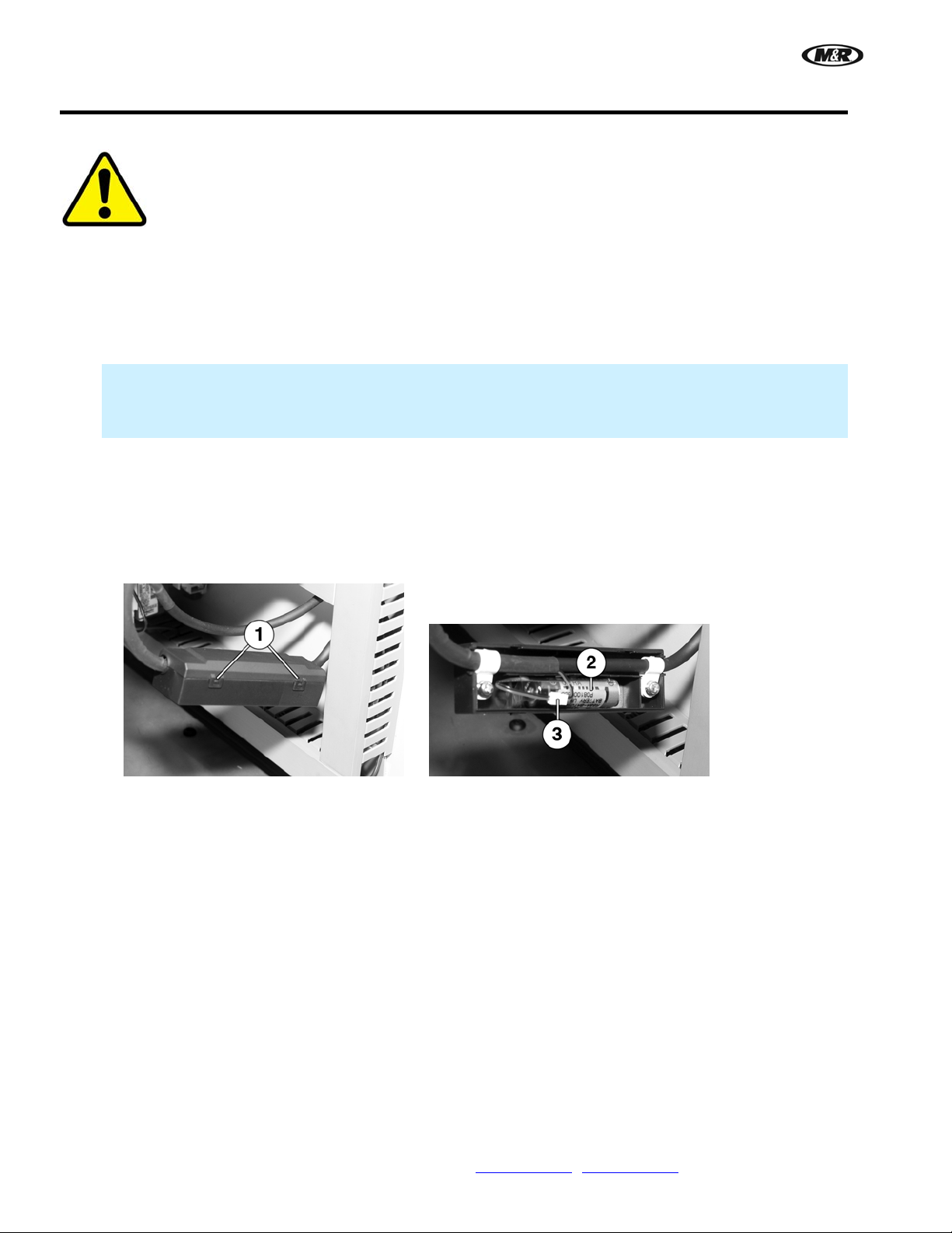
3. Open the battery cover (1).
4. Remove the old battery (2) from the hol der and pull apart the connector (3).
5. Install the new battery in reverse order and cl ose the battery cover. Replace covers.
54 M&R Companies 1N 372 Main St. Glen Ellyn, IL 60137 USA
Tel: +630-858-6101 Fax: +630-858-6134 www.mrprint.com
| store.mrprint.com
Page 55

i-Screen™
Replace PLC Battery
Items required:
1 – PLC Battery (M&R Part No. 1005097)
IMPORTANT: This procedure requires electrical power to be connected to the unit.
IMPORTANT: The new battery must be installed within (5) five minutes of removal of the old battery. This
will ensure the preservation of program data in the PLC memory.
1. Remove all the covers.
2. After removing covers, turn ON the electrical power.
3. Open the LED cover assembly on PLC (1) to expose the battery and connector.
4. Remove the old battery (2) from the hol der, then disconnect the battery by squeezing while pulling on
the connector (3).
5. Install replacement battery. Replace covers.
V.081210
M&R Companies 1N 372 Main St. Glen Ellyn, IL 60137 USA 55
Tel: +630-858-6101 Fax: +630-858-6134 www.mrprint.com
| store.mrprint.com
Page 56
i-Screen™
V.081210
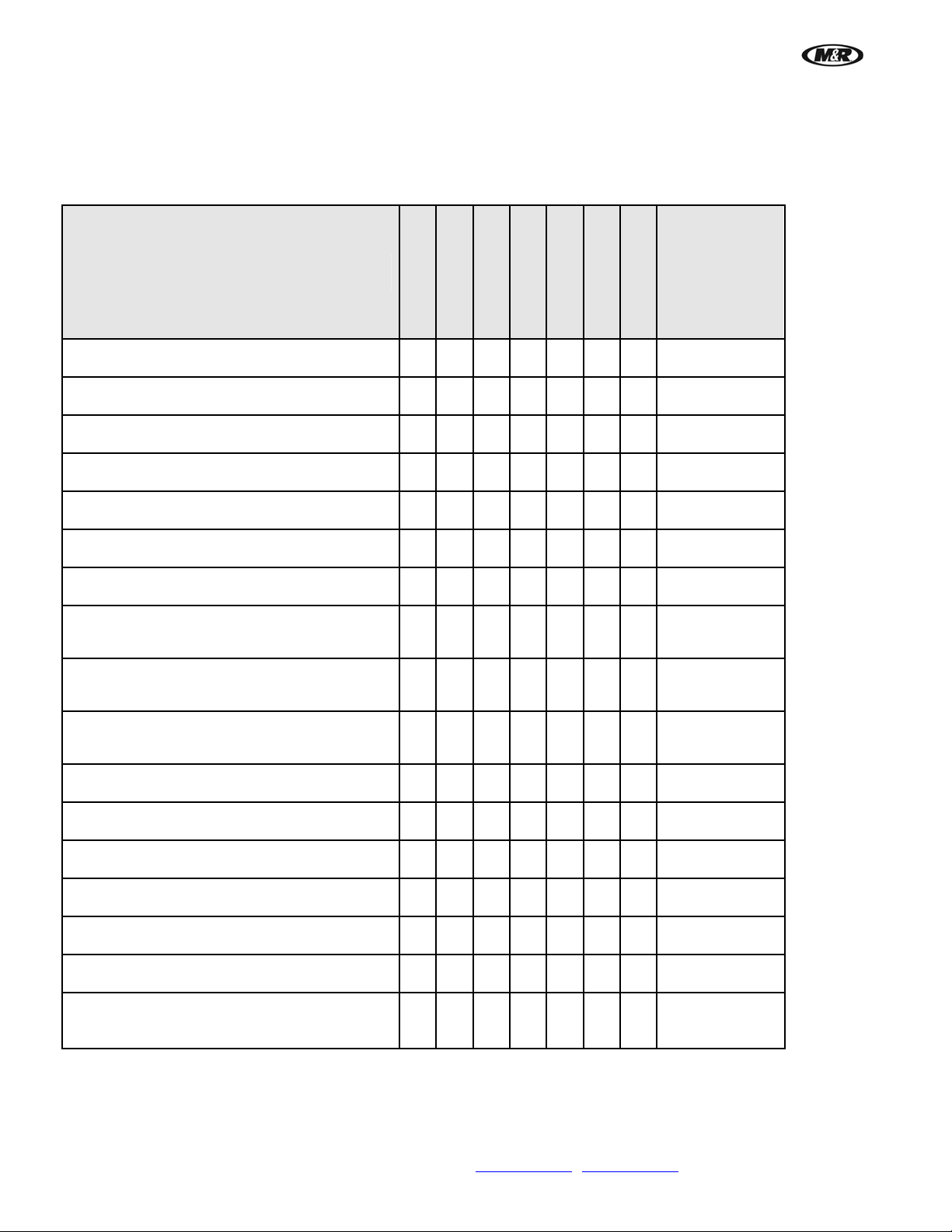
7.1 Scheduled Maintenance Log
Maintenance Procedure
As Required
Daily
Weekly
Monthly
Every 6 Months
Every 2 Years
Date
performed/
Initials
Every 3 Years
Power Cleaning
Empty Waste Bin
Fill Ink and Cleaning Solution Tanks
Clean Operator Interface Display Screen
Flushing Ink From System
Change Screen Pusher
Nozzle Check/Normal Cleaning
Normal Cleaning
Clean Capping Station and Wiper
Drain Air Filter Moisture Trap
Reset Boards
X
X
X
X
X
X
X
X
X
X
X
Clean Print Rails
Replace Print Head Excessive Ink Sponge
Lubricate Linear Bearings
Replace Air Filter Element and Reservoir Seal
Replace Servo Amplifier Battery
Replace PLC Battery
X
X
X
X
X
X
56 M&R Companies 1N 372 Main St. Glen Ellyn, IL 60137 USA
Tel: +630-858-6101 Fax: +630-858-6134 www.mrprint.com
| store.mrprint.com
Page 57

i-Screen™
V.081210
8. Replacement Parts
CE vs. UL Models
All equipment containing electrical components is designed to comply with either Conformance European (CE) or
Underwriters Laboratories (UL) standards, and each t ype of equipment has a different parts list. CE equipment
runs at 50 Hz; UL equipment runs at 60 Hz. Electrical specifications, including Hertz, can be found on the
Manufacturer’s Rating Plate similar to the one shown below.
Note: You must verify whether your equipment is 50 Hz (CE) or 60 Hz (UL) and order parts accordingly.
DANGER: Operating this equipment with incorrect electrical parts can result in severe or fatal personal injuries
and/or property damage.
Schematic Diagrams for Electrical Parts
M&R uses the ‘just-in-time’ approach to printing manuals, so the electrical parts and part numbers shown in this
section should be accurate. However, since schematic diagrams are unit-specific, they remain the most accurate
source of electrical part numbers. Cross-reference the part numbers in this manual with the part numbers in the
schematic diagrams in the back of this manual before placing an order.
M&R Companies 1N 372 Main St. Glen Ellyn, IL 60137 USA 57
Tel: +630-858-6101 Fax: +630-858-6134 www.mrprint.com
| store.mrprint.com
Page 58
i-Screen™
V.081210
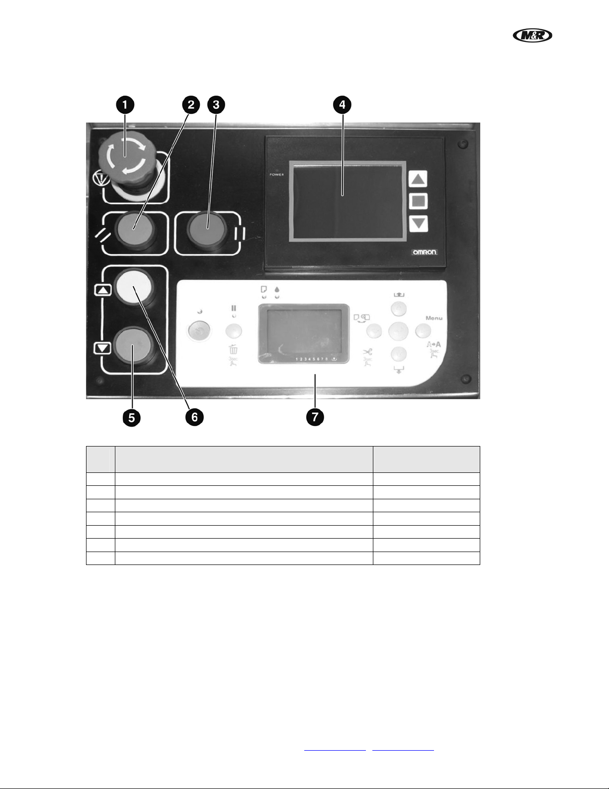
Control Panel (UL & CE)
1
Emergency Stop Button 1010400
2
Push button, Green 1010401
3
Push Button, Red 1010404A
4
Operator Interface 1017879
5
Push Button, Blue 1010403
6
Push Button, Yellow 1010404
7
Epson Control Panel —
Control Panel Assembly (UL & CE)
Part Name
Part Numbers
All Models
58 M&R Companies 1N 372 Main St. Glen Ellyn, IL 60137 USA
Tel: +630-858-6101 Fax: +630-858-6134 www.mrprint.com
| store.mrprint.com
Page 59
i-Screen™
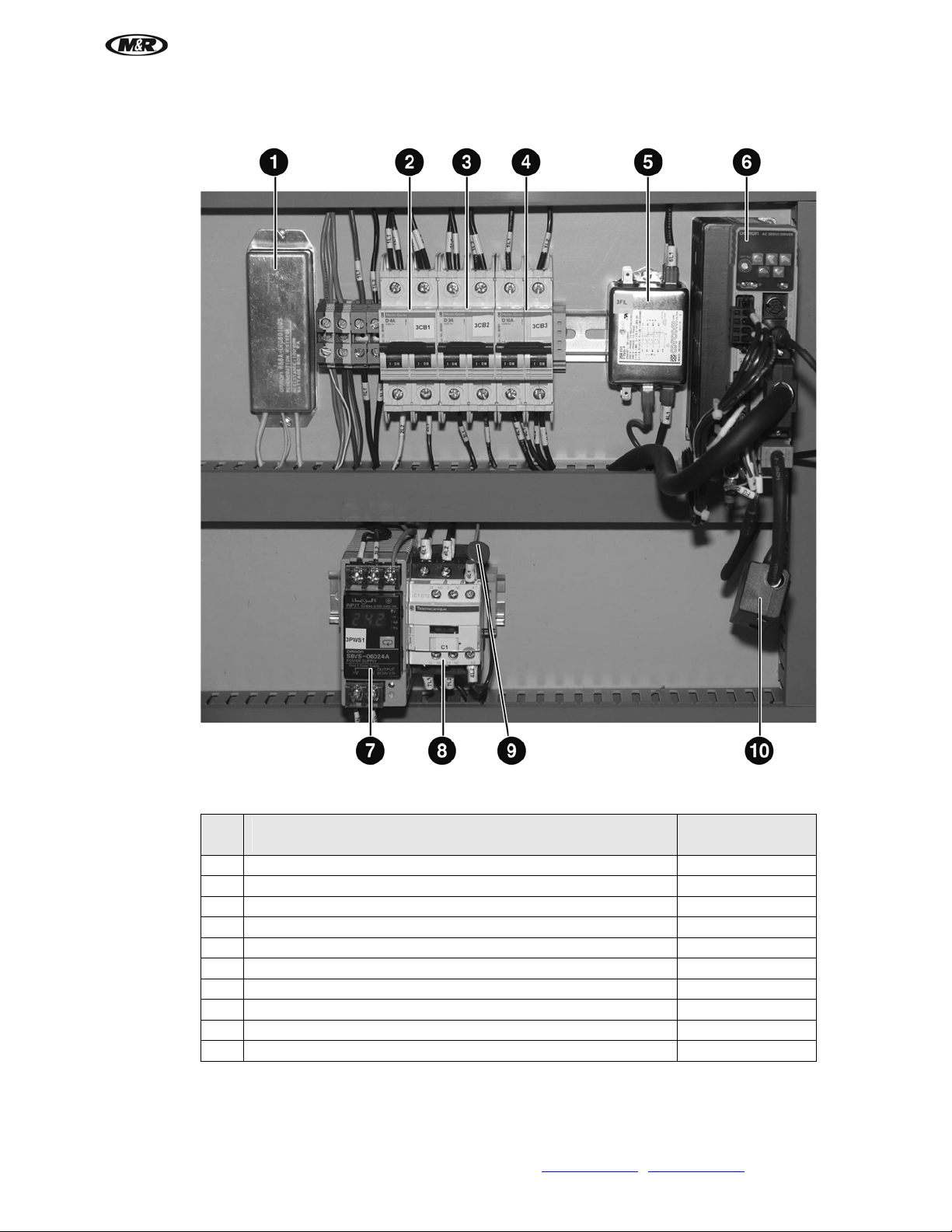
Circuit Breakers and Servo Drive (UL & CE)
V.081210
1
Regeneration Resistor 1021031
2
Circuit Breaker 2 Pole 4 Amp (CB1) 1035001
3
Circuit Breaker 2 Pole 3 Amp (CB3) 1006447
4
Circuit Breaker 2 Pole 10 Amp (CB4) 1006553
5
Power Line Filter 1036020A
6
Servo Drive 1012239
7
DC/DC Converter 1024123
8
Contactor C1 1011298
9
Varistor 1023001
10
Replacement Battery 1005091
M&R Companies 1N 372 Main St. Glen Ellyn, IL 60137 USA 59
Circuit Breakers and Servo Drive (UL & CE)
Part Name
Tel: +630-858-6101 Fax: +630-858-6134 www.mrprint.com
| store.mrprint.com
Part Numbers
All Models
Page 60
i-Screen™
V.081210
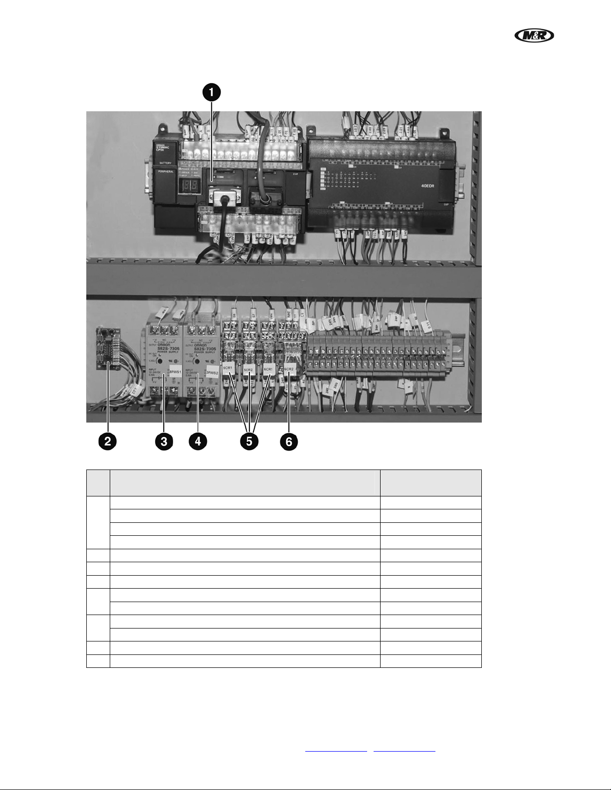
Electrical (UL & CE)
Electrical (UL & CE)
Part Name
Part Numbers
All Models
PLC 1012137
Communication Board 1012238
1
Expansion Module 1012240
Replacement Battery 1005097
2
PLC Interface Board 1092010
3
Power Supply 1008736
4
DC/DC Converter 1024123
Relay 2 Pole 1010204
5
Socket DIN Rail Mount 2 Pole 1010206
Relay 4 Pole 1011079
6
Socket DIN Rail Mount 4 Pole 1010208
7
Disconnect Switch, Safety (Not Shown) 1010008A
8
Foot Pedal Switch (Not Shown) 1020237C
60 M&R Companies 1N 372 Main St. Glen Ellyn, IL 60137 USA
Tel: +630-858-6101 Fax: +630-858-6134 www.mrprint.com
| store.mrprint.com
Page 61
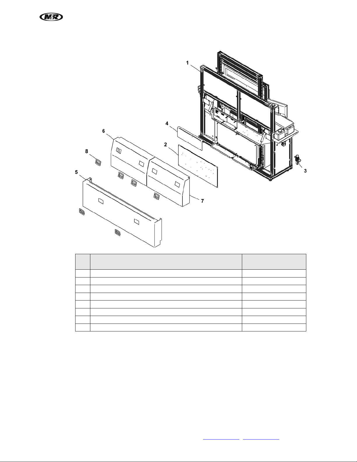
i-Screen™
Back Frame Assembly (UL & CE)
V.081210
Back Frame Assembly (UL & CE)
Part Name
Part Numbers
All Models
1 Main Chassis 9D01010
2 Electrical Sub Panel 9D01272
3 Over/Under Filter Regulator 3/8" NPT 2020036
4 Electric Board Cover 9D01093
5 Rear Cover, Bottom 9D01096
6 Rear Cover, Top/Right Side 9D01097
7 Rear Cover, Top/Left Side 9D01098
8 Flush Pull Handle 3032091
M&R Companies 1N 372 Main St. Glen Ellyn, IL 60137 USA 61
Tel: +630-858-6101 Fax: +630-858-6134 www.mrprint.com
| store.mrprint.com
Page 62
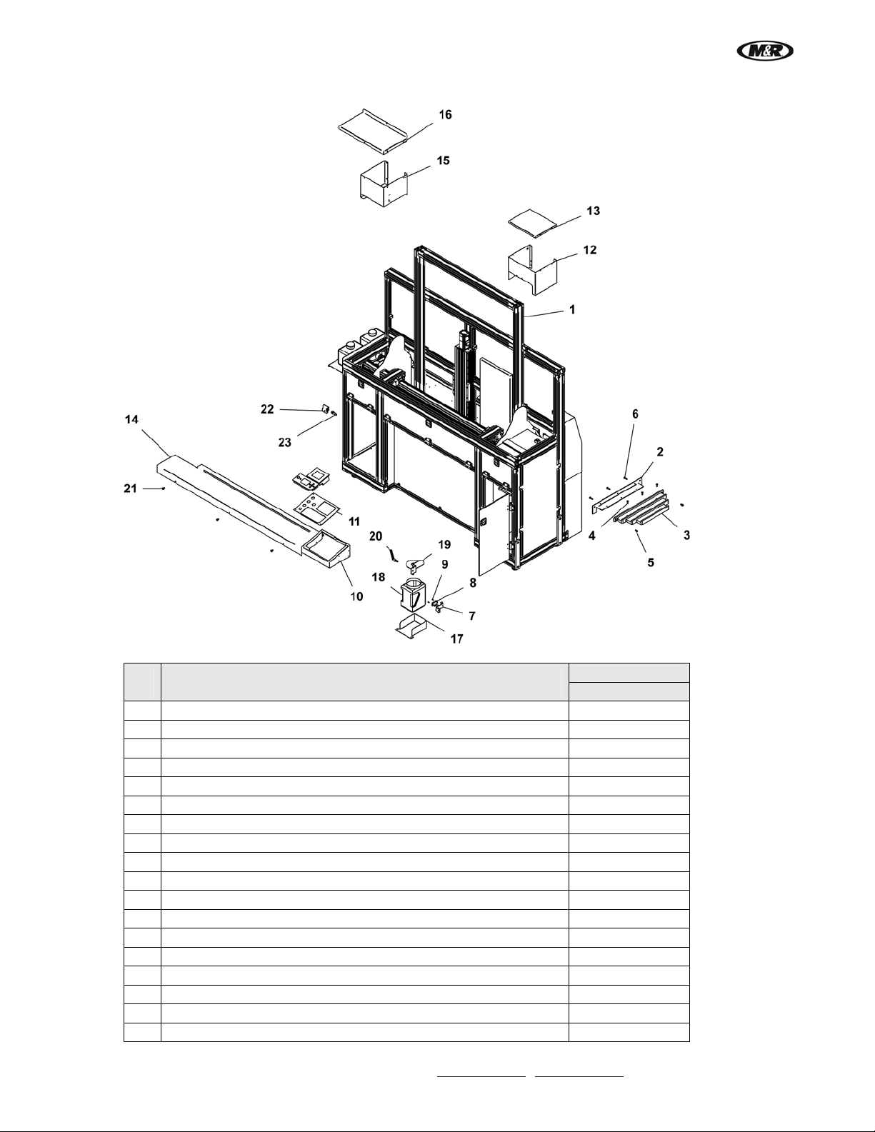
i-Screen™
V.081210
Front Frame Assembly (UL & CE)
Front Frame Assembly (UL & CE)
Part Name
Part Numbers
All Models
1 Main Chassis 9D01010
2 Pusher Frame Storage Bracket 9D0 1278
3 Pusher Frame Storage Plate 9D01279
4 Button Socket Cap Screw 1/4-20X 3/4" 3001001
5 Socket Cap Screw 5/16-18 X 1/2" 3009069
6 Flat Socket Flat Cap Screw 1/4-20 X 1" 3010005
7 Waste Ink Level Sensor 9D01223
8 Capacitive Sensor, Rectangle 1024144
9 Button Socket Cap Screw Full Thread 6-32 X 3/8" 3001016
10 Control Box 9D01104
11 Control Panel 9D01101
12 Right Top Cover 9D01108
13 Ink Tray 9D01109
14 Front Panel Desk 9D01125
15 Left Top Cover 9D01122
16 Floor Monitor 9D01123
17 Head Clean-up Ink Contai ner 9D01208
18 Plastic Container 64 oz. 7017037
62 M&R Companies 1N 372 Main St. Glen Ellyn, IL 60137 USA
Tel: +630-858-6101 Fax: +630-858-6134 www.mrprint.com
| store.mrprint.com
Page 63
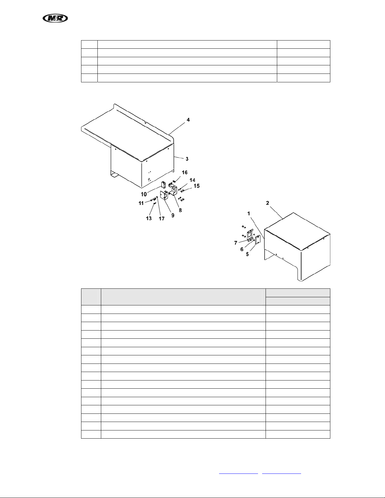
i-Screen™
19 Ink Drain Tubes Bracket 9D01207-A
20 Male Handle 1/4-20 X .590" 3032004
21 Button Socket Cap Screw Full Thre ad 5/16-18 X 1/2" 3001202
22 Screen Scan Size Sensor Bracket 9D01111
23 Proximity Switch 1010012B
Screen Sensor Assembly (UL & CE)
V.081210
Screen Sensor Assembly (UL & CE)
Part Name
Part Numbers
All Models
1 Right Top Cover 9D01108
2 Ink Tray 9D01109
3 Left Top Cover 9D01122
4 Floor Monitor 9D01123
5 Laser-Type Reflector 1024146A
6 Button Socket Cap Screw 6-32 X 1/4" 3001015
7 Laser Sensor Mirror Cover 9D01119
8 Laser Sensor Bracket 9D01118
9 Laser Sensor Swivel Bracket 9D01120
10 Laser Photoelectric Sensor 1024146
11 Pan Head Machine Screw 6-32 X 1-1/4" 3004022
13 Pan Head Machine Screw M3 X 12mm 3001191
14 Split Lock Washer ZP #8 3022013
15 Button Socket Cap Screw 8-32 x 1/4 3001079
16 Pan Head Machine Screw 6-32 X 1/4" 3004003
17 Elastic Stop Nut 6-32 3012007
M&R Companies 1N 372 Main St. Glen Ellyn, IL 60137 USA 63
Tel: +630-858-6101 Fax: +630-858-6134 www.mrprint.com
| store.mrprint.com
Page 64
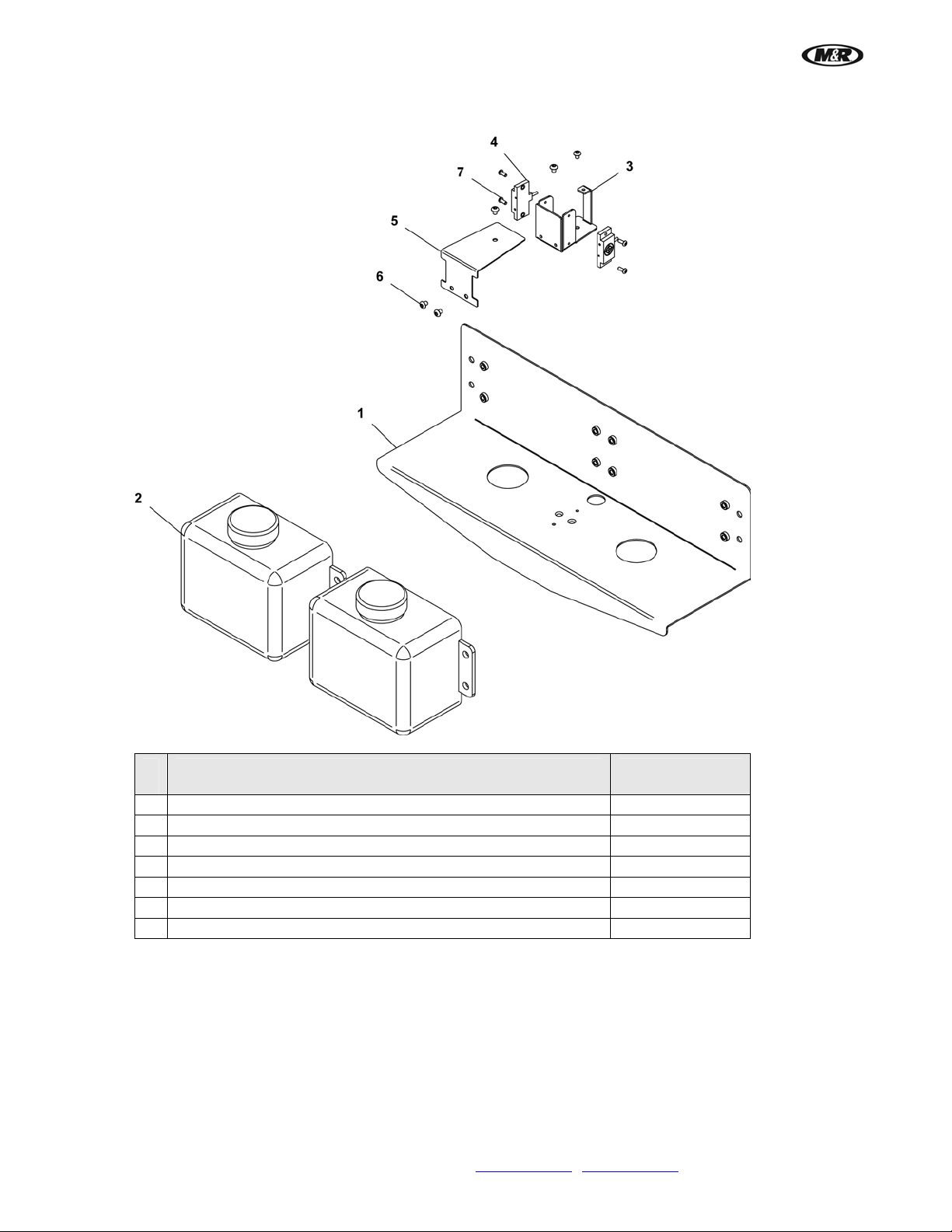
i-Screen™
V.081210
Ink Holder Assembly (UL & CE)
Ink Holder Assembly (UL & CE)
Part Name
Part Numbers
All Models
1 Ink Shelf With Nuts 9D01188
2 Multi-Purpose Tank 2 QT 2007132
3 Ink Level Sensors Bracket 9D01221
4 Capacitive Sensor, Rectangle 1024144
5 Ink Level Sensors Cover 9D01222
6 Button Socket Cap Screw 10-24 X 1/4" 3001059
7 Button Socket Cap Screw Full Thread 6 -32 X 3/8" 3001016
64 M&R Companies 1N 372 Main St. Glen Ellyn, IL 60137 USA
Tel: +630-858-6101 Fax: +630-858-6134 www.mrprint.com
| store.mrprint.com
Page 65

Holder Assembly (UL & CE)
i-Screen™
V.081210
Holder Assembly (UL & CE)
Part Name
Part Numbers
All Models
1 Electric Actuator 1036mm Stroke 2017208
2 Bottom Screen Holder 9D01057
3 Front Screen Holder 9D01056
4 Left Stopper Block 9D01061
5 Moving Stopper Block 9D01034
6 Moving Block Washer 9D01062
7 Frame Vertical Front Middle 9D01126
8 Linear Bearing Carriage 3030 113
9 Bottom Screen Holder Top Plate 9D01171
10 Cylinder Lifter Right 9D01117
11 Cylinder Lifter Bracket 9D01174
12 Lifter 9D01175
13 Socket Cap Screw M6 X 15mm 3008275
14 Pusher Lower Holder 9D01246
15 Top Pusher Adjustable Base 9D01244
16 Bumper Holder Short 9D01178
M&R Companies 1N 372 Main St. Glen Ellyn, IL 60137 USA 65
Tel: +630-858-6101 Fax: +630-858-6134 www.mrprint.com
| store.mrprint.com
Page 66
i-Screen™
V.081210
17 Snake Bracket Left 9D01176
18 Pusher Top Holder 9D01245
19 Pusher Frame Locker 9D01248
20 S.S. Knurl Thumb Screw 10-24 X 1/2" 3016041
21 Shoulder Bolt 1/4" X 1/8" 3006098
22 Air Cylinder 25mm Bore 12" Stroke 2009559
23 Neoprene Bumper 3/4" D X 5/8" LG 7002101
24 Frame (Various Sizes) Varies
25 Knurled Head Jig Screw 1/4-20 3070000
26 2 PC Split Collar 1/4" ID 3011109
27 Socket Cap Screw 1/4-28 X 1-1/2" 3009090
28 Socket Cap Screw 10-24 X 5/8" 3009045
29 Socket Cap Screw 1/4-20 X 1/2" 3009019
30 Moving Stopper Block 1.50" 9D01034-C
66 M&R Companies 1N 372 Main St. Glen Ellyn, IL 60137 USA
Tel: +630-858-6101 Fax: +630-858-6134 www.mrprint.com
| store.mrprint.com
Page 67
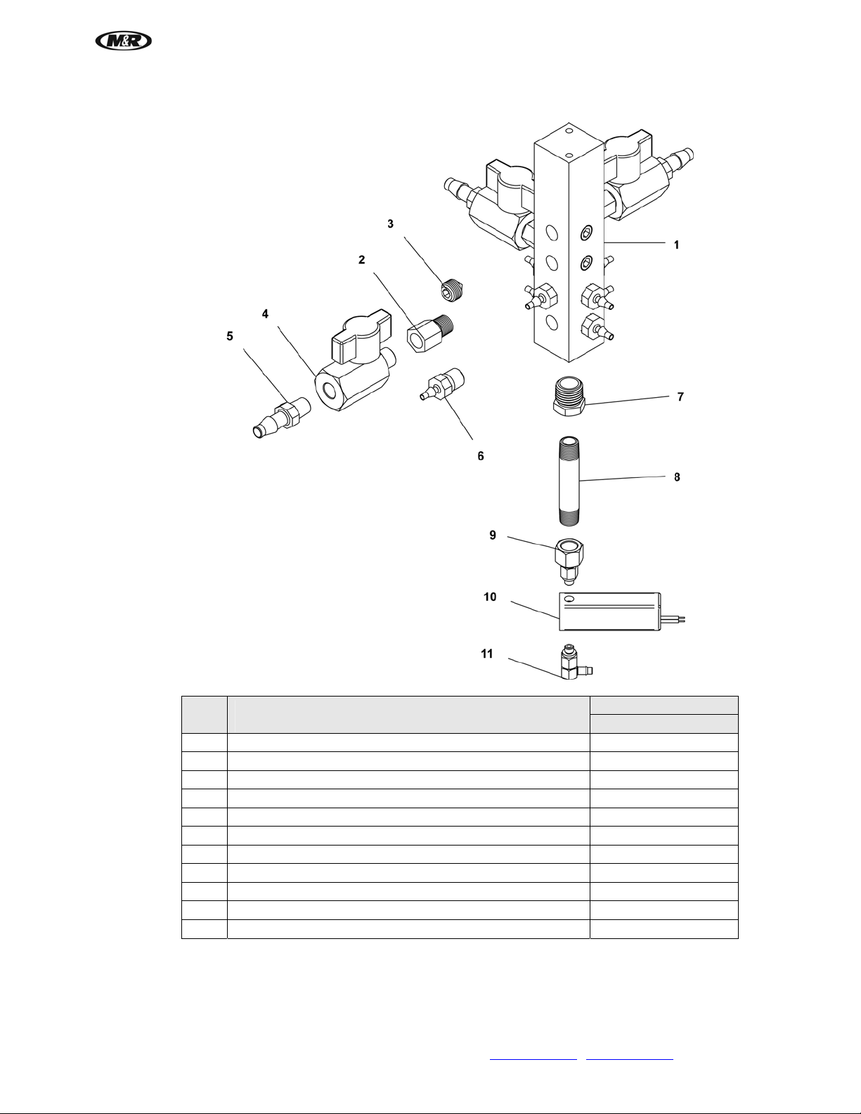
i-Screen™
Ink Manifold Assembly (UL & CE)
V.081210
Ink Manifold Assembly (UL & CE)
Part Name
Part Numbers
All Models
1 Ink Manifold 9D01189
2 Adapter Female X Male 1/8" - 1/8" 2002086
3 Hex Socket Plugs 1/8" Pipe 2005121
4 Ball Valve 1/8" NPT 2018151
5 Single Barb Tube Fitting 1/4" X 1/8" 2007137
6 Barbed Tube Fitting 1/8" X 1/8" 2007127
7 Reducing Bush 1/4" NPT - 1/8" NPT 2003357
8 Nipple 1/8" NPT X 2" Long 2003356
9 Fitting, Swivel 1/8" PT To 10-32 2003354
10 2/3 Port Solenoid Valve For Chemicals 2010201
11 Slip-On Fitting 1.8"ID X #10-32 2003355
M&R Companies 1N 372 Main St. Glen Ellyn, IL 60137 USA 67
Tel: +630-858-6101 Fax: +630-858-6134 www.mrprint.com
| store.mrprint.com
Page 68

i-Screen™
V.081210
Monitor Assembly (UL & CE)
Monitor Assembly (UL & CE)
Part Name
Part Numbers
All Models
1 Monitor Mounting Base 9D01452
2 Monitor Mounting Bracket 9D01453
3 Knob 3033136
4 Monitor Monitor
5 T-Nut 5/16-18 Thread 3012026
6 Monitor Mounting Base Adaptor 9D01454
7 Socket Cap Screw 5/16-18 X 5/8" 3009135
8 Button Socket Cap Screw 5/16 - 18 X 5/8" 3001018
9 Lock Washer M4 3020090
10 Socket Cap Screw Full Thread M4 X 24mm 3008346
11 Flat Socket Cap Screw Full Thread 1/2-13 X 1-1/4" 3010117
68 M&R Companies 1N 372 Main St. Glen Ellyn, IL 60137 USA
Tel: +630-858-6101 Fax: +630-858-6134 www.mrprint.com
| store.mrprint.com
 Loading...