

Page 1
IRPT2056A
PD 6.099
PRELIMINARY
Power Module for 3 hp Motor Drives
· 3 hp (2.2 kW) power output
Industrial rating at 150% overload for 1 minute
· 180-240V AC input, 50/60 Hz
· 3-phase rectifier bridge
· 3-phase, short circuit rated, ultrafast IGBT inverter
· HEXFRED ultrafast soft recovery-freewheeling diodes
· Brake IGBT and diode
· Low inductance (current sense) shunts in positive
and negative DC rail
· NTC temperature sensor
· Pin-to-baseplate isolation 2500V rms
· Easy-to-mount two-screw package
· Case temperature range -25°C to 125°C operational
IRPT2056A
™
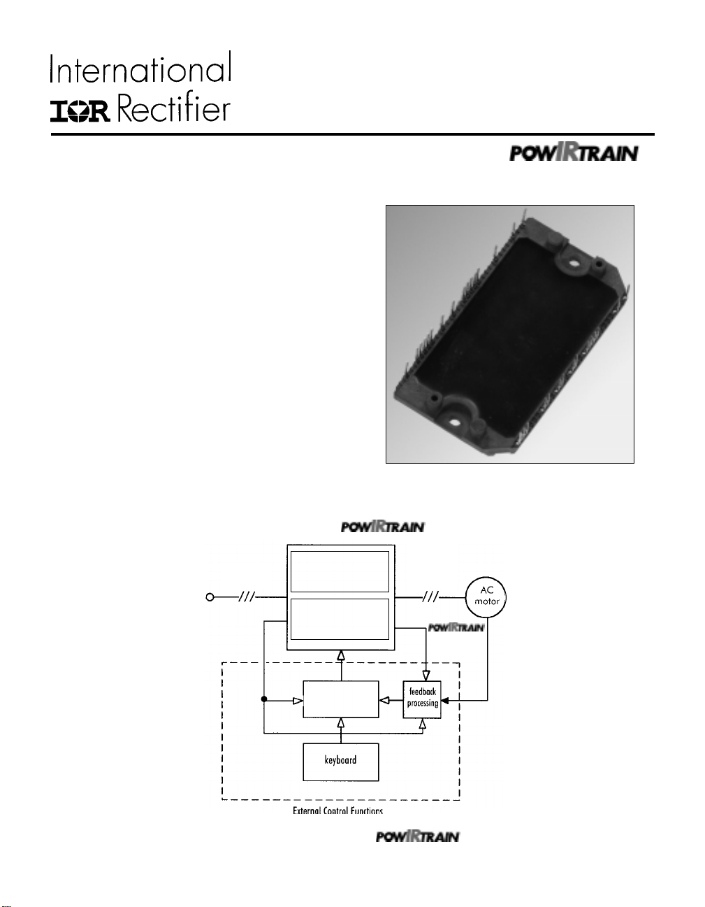
Figure 1. IRPT2056A Power Module
IRPT2056C
PWM
180-240V
3-phase input
Figure 2. The power module and within a
IRPT 2056A
Power
Module
IRPT 2056D
Driver-
Plus
Board
PWM
generator
motor control system
variable
frequency
output
feedback
(non-isolated)
page 1
Page 2

IRPT2056A
System Description
Power Module
The IRPT2056A Power Module, shown in figure 1, is a chip
and wire epoxy encapsulated module. It houses input rectifiers,
output inverter, current sense shunts and NTC thermistor. The 3phase input bridge rectifiers are rated at 800V. The brake circuit
uses 600V IGBT and freewheeling diode. The inverter section
employs 600V, short circuit rated, ultrafast IGBT's and ultrafast
freewheeling diodes. Current sensing is achieved through 25
mΩ low inductance shunts provided in the positive and negative
DC bus rail. The NTC thermistors provide temperature sensing
capability. The lead spacing on the power module meets UL840
pollution level 3 requirements.
The power circuit and layout within the module are carefully
designed to minimize inductance in the power path, to reduce
noise during inverter operation and to improve the inverter
efficiency. The Driver-Plus Board required to run the inverter
can be soldered to the power module pins, thus minimizing
assembly and alignment. The power module is designed to be
mounted to a heat sink with two screw mount positions, in order
to insure good thermal contact between the module substrate and
the heat sink.
and Design Kit
The IRPT2056C (Figure 3) provides the
complete power conversion function for a 3 hp (2.2 kW) variable
voltage, variable frequency AC motor controller. The
combines the Power Module (IRPT2056A)
with a Driver-Plus Board (IRPT2056D). The
Design Kit, IRPT2056E includes the following:
• Complete integrated power stage
• Specification and operating instructions
• Bill of materials
• Electrical schematic
• Mechanical layout of the Driver-Plus Board
• Software transferrable file for easy design integration
• Application information and layout considerations
page 2
Figure 3. IRPT2056C
Page 3

IRPT2056A
Specifications
PARAMETERS VALUES CONDITIONS
Input Power
Voltage 220V AC, -15%, +10%, 3-phase
Frequency 50/60 Hz
Current 15.4A rms @ nominal output TA = 40°C, R
I
FSM
400A 10ms half-cycle, non-repetitive surge
Output Power
Voltage 0-230V rms defined by external PWM control
Nominal motor hp (kW) 3 hp (2.2 kW) nominal full load power Vin = 230V AC, f
Nominal motor current 11A nominal full load power T
150% overload for 1 minute fo = 60 Hz,
= 40°C, R
16.5A 150% overload for 1 minute
A
DC Link
DC link voltage 400V maximum
Brake
Current 20A
Sensor
Temp. sense resistance 50 kOhms ±5% @ T
3.1kOhms ±10% @ T
Current sense 25mOhms ±5% @ T
Protection
IGBT short circuit time 10 µs DC bus = 400V, VGE = 15V,
line to line short
Recommended short circuit- 70A peak
shutdown current
Gate Drive
Q
G
Recommended gate driver IR2133 (see Figure 10)
120 nC (typical) @ VGE = 15V, refer figure 5b
Module
Isolation voltage 2500V rms pin-to-baseplate, 60 Hz, 1 minute
Operating case temperature -25°C to 125°C 95% RH max. (non-condensing)
Mounting torque 1 Nm M4 screw type
Storage temperature range -40°C to 125°C
Soldering temperature for 10 sec. 260°C maximum at the pins (.06" from case)
thSA
thSA
NTC
NTC
SHUNT
= 25°C
= 100°C
= 25°C
= 0.42°C/W
= 4kHz,
pwm
= 0.42°C/W
page 3
Page 4
IRPT2056A
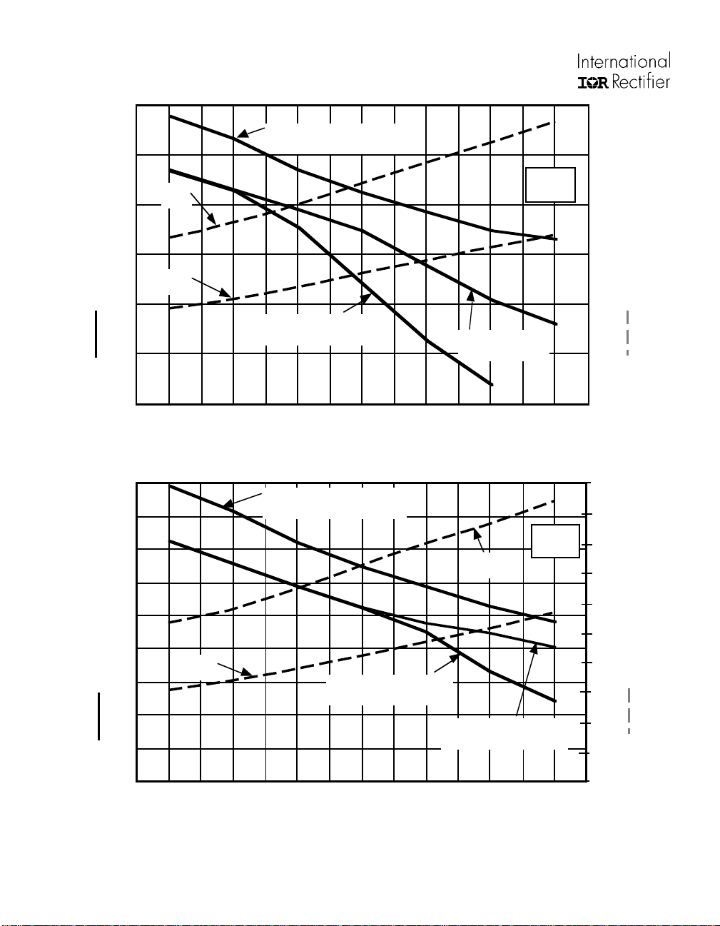
0.6
0.5
°C/W)
thSA
0.4
0.3
Power
150%
R
100% Load Continuous
thSA
10-60 Hz
3 hp
(2.2 kW)
300
250
200
150
Power
100%
Thermal Resistance (R
0.2
0.1
R
150% Load (1 min.)
thSA
Down to 3 Hz
0
1 4 8 12 20
R
150% Load
thSA
1 min.)10-60 Hz
16 24
100
50
0
PWM Frequency (kHz) – (Induction Motor Load)
Figure 4a. 3hp/11A output Heat Sink Thermal Resistance and Power Dissipation vs. PWM Frequency
0.9
0.8
0.7
°C/W)
thSA
0.6
R
100% Load Continuous
thSA
10-60 Hz
Power
150%
2 hp
(1.5 kW)
200
180
160
140
120
0.5
100
0.4
0.3
Thermal Resistance (R
0.2
0.1
Power
100%
R
150% Load (1 min.)
thSA
Down to 3 Hz
R
150% Load (1 min.)
thSA
10-60 Hz
80
60
40
20
Total Power Dissipation (Watts)
Total Power Dissipation (Watts)
0
1 4 8 12 16 20 24
PWM Frequency (kHz) – (Induction Motor Load)
Figure 4b. 2hp/8A output Heat Sink Thermal Resistance and Power Dissipation vs. PWM Frequency
NOTE: For Figures 4a and 4b: Operating Conditions: Vin = 230V
during 1 minute overload to 10°C
page 4
, MI =1.15, PF = 0.8, TA = 40°C, Tj < 145°C, Ts < 95°C, Z
rms
0
thSA
limits ∆T
c
Page 5

IRPT2056A
(
3000
=
0V,
2500
2000
1500
1000
V
GE
C
=
ies ge gc , ce
C
=
res
C
=
oes ce gc
C
C
C
C
ies
+ C
gc
+ C
f = 1MHz
C SHORTED
C, Capacitance (pF)
C
500
0
1 10 100
100
oes
C
res
V , Collector-to-Emitter Voltage
CE
Figure 5a. Typical Capacitance vs
Collector-to-Emitter Voltage
20
CC
V = 400V
C
I = 25A
16
12
8
4
GE
V , Gate-to-Emitter Voltage (V)
0
0 20406080100120140
Q , Total Gate Charge (nC)
G
Figure 5b. Typical Gate Charge vs
Gate-to-Emitter Voltage
T = 150°C
J
T = 25°C
10
C
I , Collector-to-Emitter Current (A)
1
5 7911
V , Gate-to-Emitter Voltage (V)
GE
Figure 5c. Typical Transfer Characteristics Figure 6. Nominal R-T Characteristics of the
J
V = 50V
CC
5µs PULSE WIDTH•
A
NTC␣ Thermistor
page 5
Page 6

IRPT2056A
0
0
0
0
0
0
0
0
0
0
Mounting, Hookup and Application Instructions
Mounting
1. Connect the driver board and the IRPT2056A module.
2. Remove all particles and grit from the heat sink and power
substrate.
3. Spread a .004" to .005" layer of silicone grease on the heat
sink, covering the entire area that the power substrate will
occupy. Recommended heat sink flatness in .001 inch/inch and
Total Indicator Readout (TIR) of .003 inch below substrate.
4. Place the power substrate onto the heat sink with the
mounting holes aligned and press it firmly into the silicone
grease.
5. Place the 2 M4 mounting screws through the PCB and
power module and into the heat sink and tighten the screws to
1 Nm torque.
2345678901234567890123456789
2345678901234567890123456789
2345678901234567890123456789
2345678901234567890123456789
2345678901234567890123456789
2345678901234567890123456789
2345678901234567890123456789
1 2
2345678901234567890123456789
2345678901234567890123456789
2345678901234567890123456789
Figure 7. Power Module Mounting Screw Sequence
Power Connections
The power module pin designation, function and other details
can be obtained from the package outline (figure 8) and circuit
diagram (figure 9). 3-phase input connections are made to pins
R, S and T and inverter output connections are made to pins U,
V and W. Positive DC bus and brake IGBT collector
connections are brought out to pins P and BR, respectively.
Positive rectifier output and positive inverter bus are brought out
to pins RP and P, respectively, in order to provide DC bus
capacitor soft charging implementation option. The current
shunt terminals are connected to pins IS1, IS2 and IS3, IS4 on
the positive and negative DC rails, respectively.
page 6
Page 7

IRPT2056A Mechanical Specifications
NOTE: Dimensions are in inches (millimeters)
IRPT2056A
2.105
[53.47]
1.662
[42.21]
3.854
[97.89]
3.215
[81.66]
R
N
T
S
P
E1
G1
RP
IS2
IS1
E2
G2
IS3
IS4
G7
BR
E5
E3
G5
G3
E4
G4
V
U
N/C
RT2
RT1
N/C
W
E6
G6
Figure 8a. Package Outline and Mechanical Specifications
HATCHED SURFACE
.032 [0.81]
31X
.020 [0.51]
THICKNESS
2.040 [51.82]
HATCHED SURFACE
F
.650
[16.51]
.307
[7.80]
.507
[12.87]
E
page 7
Page 8

IRPT2056A
IRPT2056A Mechanical Specifications
NOTE: Dimensions are in inches (millimeters)
ALL PIN COORDINATE DIMENSIONS ARE BASIC
3.420 [86.87]
2X .104
MINUS DRAFT X .400
.002
±
Ø
±
[2.64 0.05]
.010 A B-C
S
Ø
G
.800 [20.32]
.400 [10.16]
4X .260 [6.60]
Ø
HATCHED SURFACE
.050 [ 1.27]
.450 [11.43]
.350 [ 8.89]
.550 [13.97]
C
31X ( .026 - .024)
31X .050 [1.27]
F
.650 [16.51]
1.250 [31.75]
1.550 [39.37]
.950 [24.13]
1.450 [36.83]
1.750 [44.45]
.050 [ 1.27]
.000 [ 0.00]
.250 [ 6.35]
.150 [ 3.81]
.350 [ 8.89]
.450 [11.43]
.250 [ 6.35]
.550 [13.97]
.850 [21.59]
.750 [19.05]
1.050 [26.67]
.950 [24.13]
Figure 8b. Package Outline and Mechanical Specifications
1.350 [34.29]
1.450 [36.83]
1.550 [39.37]
1.020 [25.91]
PIN CENTER
.187 [4.75]
2X
.175 [4.45]
.000 [ 0.00]
2X R .250 [6.35]
PIN CENTER
1.020 [25.91]
PIN DIAGONAL
.037 - .034
[.940 - .864]
1.250 [31.75]
1.150 [29.21]
31X
M
.019 E-F G B-C
Ø
.010 E-FM
Ø
E
HATCHED SURFACE
MOUNTING SURFACE IN CLAMPED CONDITION
A
B
page 8
Page 9

IRPT2056A
RP P
D7 D9 D11 D13
R
S
T
D8 D10 D12
N BR G7 IS4 1S3 G2 E2 G4 E4 G6 E6
IS1 IS2 E1G1
RS1
Q7
RS2
E3 G3 E5 G5 RT1 RT2
Q1
D1
Q2
D2
Figure 9. Power Module Circuit Diagram
Q3
Q4
Q5
Q6
D5
RT
U
V
W
D6
D3
D4
Figure 10. Recommended Gate Drive Circuit
page 9
Page 10

IRPT2056A
Functional Information
Heat Sink Requirements
Figures 4a through 4b show the thermal resistance of the heat
sink required for various output power levels and pulse-widthmodulated (PWM) switching frequencies. Maximum total losses
of the unit are also shown. This data is based on the following
key operating conditions:
• The maximum continuous combined losses of the rectifier
and inverter occur at full pulse-width-modulation. These
losses set the maximum continuous operating temperature
of the heat sink.
• The maximum combined losses of the rectifier and inverter
at full pulse-width modulation under overload set the
incremental temperature rise of the heat sink during
overload.
• The minimum output frequency at which full load current
is to be delivered sets the peak IGBT junction temperature.
• At low frequency, IGBT junction temperature tends to
follow the instantaneous fluctuations of the output current.
Thus, peak junction temperature rise increases as output
frequency decreases.
Over-Temperature Protection
Over-temperature can be detected using the NTC thermistor
included in the power module for thermal sensing. A protection
circuit that initiates a shutdown if the temperature of the IMS
exceeds a set level can be implemented. The nominal resistance
vs. temperature characteristic of the thermistor is given in
figure 6.
Voltage Rise During Braking
The motor will feed energy back to the DC link during
regenerative braking, forcing the bus voltage to rise above the
level defined by the input voltage. Deceleration of the motor
must be controlled by appropriate PWM control to keep the DC
bus voltage within the rated maximum value. For high inertial
loads, or for very fast deceleration rates, this can be achieved by
connecting an external braking resistor across P and BR and
controlling the brake IGBT switching when the bus voltage
exceeds the allowable limit.
page 10
Page 11

IRPT2056A
Part Number Identification and Ordering Instructions
IRPT2056A Power Module
Chip and wire epoxy encapsulated module with 800V input
rectifiers, 600V brake IGBT and freewheeling diode, 600V
short-circuit rated, ultra-fast IGBT inverter with ultra-fast
freewheeling diodes, NTC temperature sensing thermistor and
current sensing low-inductance shunts.
IRPT2056C Complete
IRPT2056A Power Module and IRPT2056D Driver-Plus
Board pre-assembled and tested to meet all system
specifications.
IRPT2056D Driver-
Printed circuit board assembled with DC link capacitors.
NTC in-rush limiting thermistors, high-power terminal blocks,
surge suppression MOVs, IGBT gate drivers, protection circuitry
and low power supply. The PCB is functionally tested with
standard power module to meet all system specifications.
Plus
Board
IRPT2056E Design Kit
Complete (IRPT2056C) with full set of
design documentation including detailed schematic diagram, bill
of material, mechanical layout, schematic file, Gerber files and
design tips.
page 11
Page 12

IRPT2056A
WORLD HEADQUARTERS: 233 Kansas St., El Segundo, California 90245, Tel: (310) 322 3331
EUROPEAN HEADQUARTERS: Hurst Green, Oxted, Surrey RH8 9BB, UK Tel: ++ 44 1883 732020
IR CANADA: 7321 Victoria Park Ave., Suite 201, Markham, Ontario L3R 2Z8, Tel: (905) 475 1897
IR GERMANY: Saalburgstrasse 157, 61350 Bad Homburg Tel: ++ 49 6172 96590
IR FAR EAST: 171 (K&H Bldg.), 3-30-4 Nishi-ikebukuro 3-Chome, Toshima-ku, Tokyo Japan Tel: 81 3 3983 0086
IR SOUTHEAST ASIA: 315 Outram Road, #10-02 Tan Boon Liat Building, Singapore 0316 Tel: 65 221 8371
page 12
http://www.irf.com/ Data and specifications subject to change without notice. 5/97
IR ITALY: Via Liguria 49, 10071 Borgaro, Torino Tel: ++ 39 11 451 0111
 Loading...