

Page 1

INSTRUMENT PANEL
I BODY
A
B
SECTION IP
CONTENTS
PRECAUTIONS .......................................................... 2
Precautions for Supplemental Rest raint System
(SRS) “AIR BAG” and “SEAT BELT PRE-TEN-
SIONER” .................................................................. 2
Precautions .............................................................. 2
PREPARATION ........... ................... .................... ......... 3
Special Service Tools ............................................... 3
Commercial Service Tools ........................................ 3
SQUEAK AND RATTLE TROUBLE DIAGNOSES ..... 4
Work Flow ................................................................ 4
CUSTOMER INTERVIEW ..................................... 4
DUPLICATE THE NOISE AND TEST DRIVE ....... 5
CHECK RELATED SERVICE BULLETINS .. ......... 5
LOCATE THE NOISE AND IDENTIFY THE
ROOT CAUSE ................................ ...... ....... ......... 5
REP AIR THE CAUSE ........................................... 5
CONFIRM THE REPAIR ....................................... 6
Generic Squeak and Rattle Troubleshooting ........... 6
INSTRUMENT PANEL .......................................... 6
CENTER CONSOLE ............................................. 6
INSTRUMENT PANEL
DOORS .................................................................6
TRUNK .................................................................. 7
SUNROOF/HEADLINING ..................................... 7
SEATS ............................ ....................................... 7
UNDERHOOD ....................... ................................7
Diagnostic Worksheet ............................................... 8
INSTRUMENT PANEL ASSEMBLY ......................... 10
Component Parts Drawing ..................................... 10
Removal and Installation ........................................ 11
WORK STEP ....................................................... 11
REMOVAL ........................................................... 12
INSTALLATION ...................................................16
Disassembly and Assembly ....................................17
CLUSTER LID A .................................................. 17
CLUSTER LID C .................................................18
GLOVE BOX ASSEMBLY ................................... 19
CENTER BOX ASSEMBLY ...................... ....... ....20
CENTER CONSOLE (A/T MODELS) .................. 21
CENTER CONSOLE (M/T MODELS) .................22
C
D
E
F
G
H
IP
J
K
L
Edition; 2004 September 2005 G35 Sedan
IP-1
M
Page 2

PRECAUTIONS
PRECAUTIONS PFP:00001
Precautions for Supplemental Restraint System (SRS) “AIR BAG” and “SEA T
BELT PRE-TENSIONER”
The Supplemental Restraint System such as “AIR BAG” and “SEAT BELT PRE-TENSIONER”, used along
with a front sea t belt , helps t o redu ce th e r isk or s everi ty of injury to th e driv er an d front passenge r for c ertain
types of collisi on . Thi s s ys te m in cludes seat belt swi tch inp uts an d du al stage front air bag modules . The SRS
system uses the seat belt switches to determine the front air bag deployment, and may only deploy one front
air bag, depending on the severity of a collision and whether the front occupants are belted or unbelted.
Information ne ce ss ary t o se rvi ce th e sy stem saf e ly is i nclu de d in th e SR S and SB se ct i on of th is Ser vic e Manual.
WARNING:
● To avoid rendering the SRS inoperativ e, which cou ld increase the risk of persona l injury or death
in the event of a collision which would result in air bag inflation, all maintenance must be performed by an authorized NISSAN/INFINITI dealer.
● Improper maintenance, in cluding incorrect removal a nd installation of the SRS, can lead to per-
sonal injury caused by unintentional activation of the system. For rem ova l of Sp iral Ca ble an d Air
Bag Module, see the SRS section.
● Do not use electrical test equipme nt on any circuit related to the SRS unle ss instructed to in this
Service Manual. SRS wiring harnesses can be identified by yellow and/or orange harnesses or
harness connectors .
AIS000BC
Precautions AIS0008M
● Disconnect both battery cab les in advance.
● Disconnect air bag system line in advance.
● Never tamper with or force air bag lid open, as this may adversely affect air bag performance.
● Be careful not to scratch pad and other parts.
● When removing or disassembling any part, be careful not to damage or deform it. Protect parts, which
may get in the way with cloth.
● When removing parts with a screwdriver or other tool, protect parts by wrapping them with vinyl or tape.
● Keep removed parts protected with cloth.
● If a clip is deformed or damaged, replace it.
● If an unreus able part is r emoved, replace it with a new one.
● Tighten bolts and nuts firmly to the specified torque.
● After re-assembly has been completed, make sure each part functions correctly.
● Remove stains in the following way.
Water- s oluble stai ns:
Dip a soft cloth in warm water, and then squeeze it tigh tly. After wiping the stain , wipe with a soft dry cloth.
Oil stain:
Dissolve a synthetic detergent in warm water (density of 2 to 3% or less), dip the cloth, then clean off the st ain
with the cloth. Nex t, di p t he clot h i n f resh wat er and squ ee ze i t tigh tl y. Then clean off th e de t erg en t co mp let el y.
Then wipe the area with a soft dry cloth.
● Do not use any or ganic solvent, su ch as thinner or be nzine.
Edition; 2004 September 2005 G35 Sedan
IP-2
Page 3
PREPARATION
PREPARATION PFP:00002
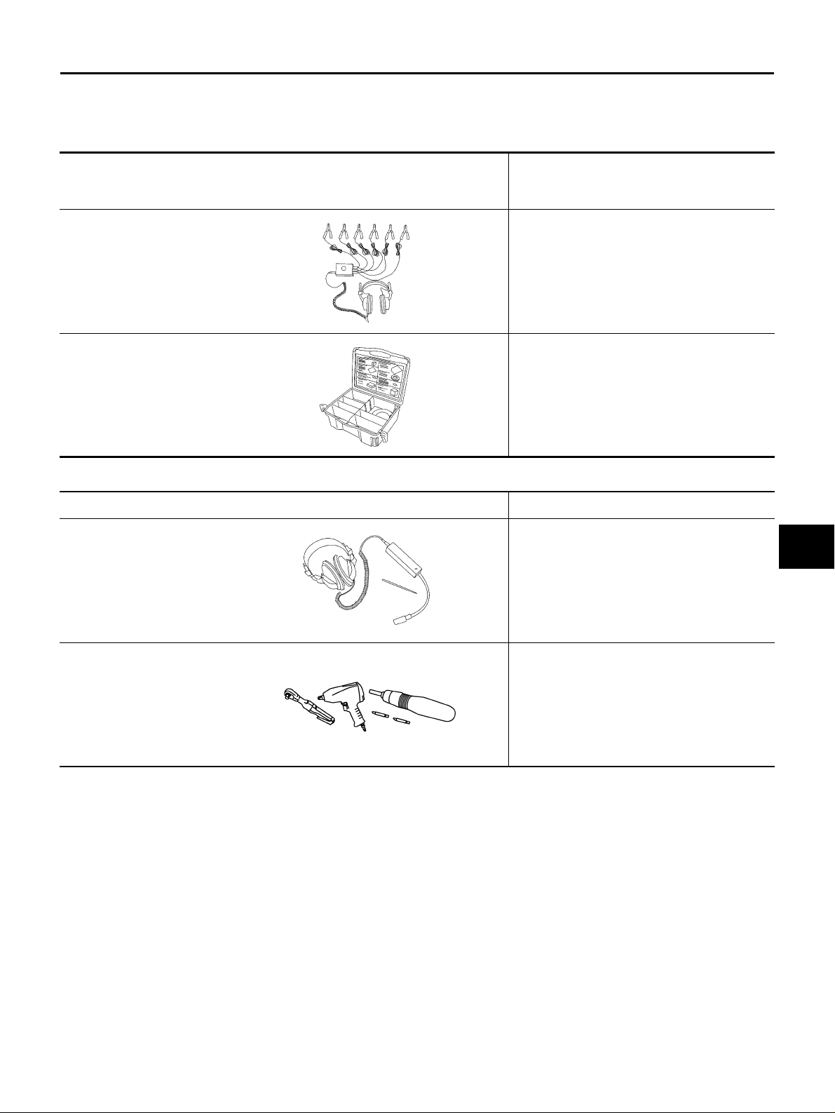
Special Service Tools AIS0008N
The actual shapes of Kent-Moore tools may differ from those of special service tools illustrated here.
Tool number
(Kent-Moore No.)
Tool name
Description
A
B
C
(J39570)
Chassis ear
SIIA0993E
(J43980)
NISSAN Squeak and Rattle
Kit
SIIA0994E
Locating the noise
Repairing the cause of noise
Commercial Service Tools AIS0008O
Tool name Description
Engine ear Locating the noise
SIIA0995E
D
E
F
G
H
IP
J
K
Power tool
PIIB1407E
Edition; 2004 September 2005 G35 Sedan
IP-3
L
M
Page 4
SQUEAK AND RATTLE TROUBLE DIAGNOSES
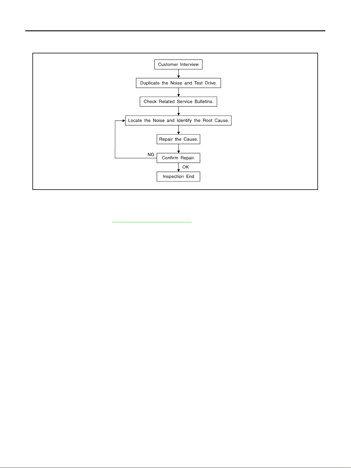
SQUEAK AND RATTLE TROUBLE DIAGNOSES PFP:00000 Work Flow AIS0008P
SBT842
CUSTOMER INTERVIEW
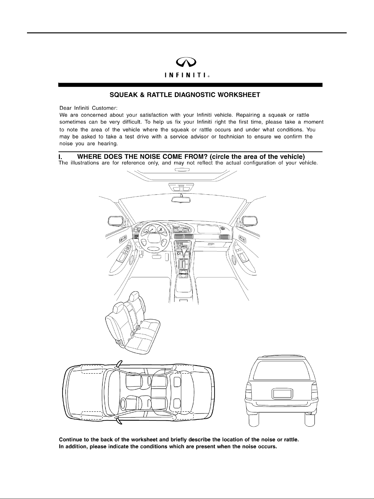
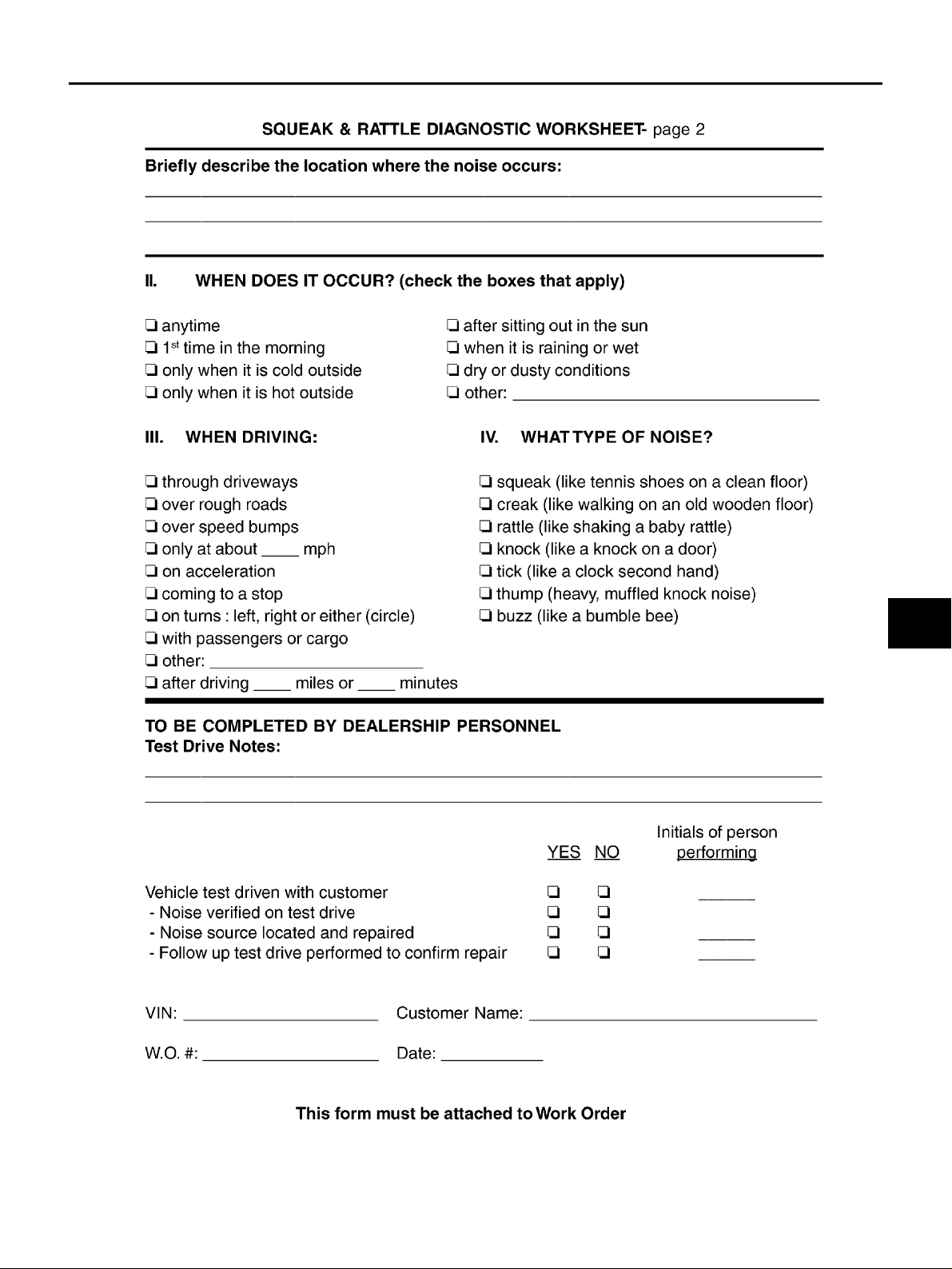
Interview the cus to me r if po ss ib le , to de t ermi n e th e co nd iti on s th at exi st whe n th e no is e occu r s. Use th e D iagnostic Worksheet durin g the interview to docum ent the facts and conditio ns when the noise occu rs and any
customer's comments; refer to IP-8, "
conditions that exist when the noise occur s .
● The customer ma y not be able to provide a detailed description or t he location of th e noise. Attempt to
obtain all the facts and conditions that exist when the noise occurs (or does not occur).
● If there is more than one n oise in th e veh icle , be s ure to di agno se an d repair th e noi se th at the cus tome r
is concerned about. This can be accomplished by test driving the vehicle with the customer.
● After identifying the type of noise, isolate the noise in terms of its characteristics. The noise characteristics
are provided s o the cus tomer, service adviser and techni cian are al l speaking the same language w hen
defining the noise.
● Squeak —(Like tennis shoes on a clean floor)
Squeak characteristics include the light contact/fast movement/brought on by road conditions/hard surfaces=higher pitch noise/softer surfaces=lower pitch noises/edge to sur face=chirping
● Creak—(Like walking on an old wooden floor)
Creak characteristics include firm contact/slow movement/twisting with a rotational movement/pitch
dependent on materials/often brought on by activity.
● Rattle—(Like shaking a baby rattle)
Rattle charac teristic s inclu de the fast repe ated c ontact/vibrat ion or simila r moveme nt/loose parts/missi ng
clip or fastener/incorrect clearance.
● Knock —(Like a knock on a door)
Knock characteristics include hollow sounding/sometimes repeating/often brought on by driver action.
● Tick—(Like a clock second hand)
Tick characteristi cs include gentle contacting of light m aterials/loose components/can be caused by driver
action or road conditions.
● Thump—(Hea vy, muffled knock noise)
Thump characteristics incl ude softer knock/dead sound often brought on by activity.
● Buzz—(Like a bumble bee)
Buzz characteristics incl ude high frequen c y rattle/firm contact.
● Often the degree of acceptable noise level will vary depending upon the person. A noise that you may
judge as acceptable may be very irritating to the customer.
● Weather conditions, especially humid ity and temperature, may have a gr eat effect on noise level.
Diagnostic Worksheet" . This information is necessar y to duplicate the
Edition; 2004 September 2005 G35 Sedan
IP-4
Page 5

SQUEAK AND RATTLE TROUBLE DIAGNOSES
DUPLICATE THE NOISE AND TEST DRIVE
If possible, drive the vehicle with the customer until the noise is duplicated. Note any additional information on
the Diagnostic Works heet regarding the co nditions or locatio n of the noise. This in formation can be used to
duplicate the same conditions when you confirm the repair.
If the noise can be duplicated easily during the test drive, to help identify the source of the noise, try to duplicate the noise with the vehicle stopped by doing one or all of the following:
1) Close a door.
2) Tap or push/pull around the area where the noise appears to be coming from.
3) Rev the engine.
4) Use a floor jack to recreate vehicle “twist”.
5) At idle, apply engine load (electrical load, half-clutch on M/T model, drive position on A/T model).
6) Raise the vehicle on a hoist and hit a tire with a rubber hammer.
● Drive the vehicle an d att em pt to dup li ca te th e co nd iti on s th e cu stom er st at e s exi st w he n the no is e oc cu rs.
● If it is difficult to duplicate the noise, drive the vehicle slowly on an undulating or rough road to stress the
vehicle body.
CHECK RELATED SERVICE BULLETINS
After verifying the customer concern or symptom, check ASIST for Technical Service Bulletins (TSBs) related
to that concern or symptom.
If a TSB relates to the symptom, follow the procedure to repair the noise.
A
B
C
D
E
F
LOCATE THE NOISE AND IDENTIFY THE ROOT CAUSE
1. Narrow down the noise to a general area. To help pinpoint the source of the noise, use a listening tool
(Chassis Ear: J39570, Engi ne Ear and mechanics stethoscope).
2. Narrow down the noise to a more specific area and identify the cause of the noise by:
● removing the components in the area that you suspect the noise is coming from.
Do not use too much force when removing clips and fasteners, otherwise clips and fastener can be broken
or lost during the repair, resulting in the creation of new noise.
● tapping or pushing/pulling the component that you suspect is causing the noise.
Do not tap or pu sh/pull the c omponent with excessive fo rce, otherwise the noise will be eliminated only
temporarily.
● feeling for a vibration with your hand by touching the component(s) that you suspect is (are) causing the
noise.
● placing a piece of paper between components that you suspect are causing the noise.
● looking for loose components and contact marks.
Refer to IP-6, "
Generic Squeak and Rattle Troubleshooting" .
REPAIR THE CAUSE
● If the cause is a loose component, tighten the component securely.
● If the cause is insufficien t clearance bet ween components:
– separate components by repositioning or loosening and retightening the component, if possible.
– insulate components with a suitable insulator such as urethane pads, foam blocks, felt cloth tape or ure-
thane tape. A NISSAN Squeak and Rattle Kit (J43980) is available through your authorized NISSAN Parts
Department.
CAUTION:
Do not use excessive force as many components are constructed of plastic and may be damaged.
Always check with the Parts Department for the latest parts information.
The following materials are contained in the NISSAN Squeak and Rattle Kit (J43980). Each item can be
ordered separately as needed.
URETHANE PADS [1.5 mm (0.059 in) thick]
Insulates connectors, harness, etc.
76268-9E005: 100 × 135 mm (3.94 × 5.31 in)/76884-71L01: 60 × 85 mm (2.36 × 3.35 in)/76884-71L02: 15
× 25 mm (0.59 × 0.98 in)
INSULATOR (Foam blocks)
Insulates components from contact. Can be used to fill space behind a panel.
73982-9E000: 45 mm (1.77 in) thick, 50 × 50 mm (1.97 × 1.97 in)/73982 - 50 Y00 : 10 mm (0.39 in) thick,
50 × 50 mm (1.97 × 1.97 in)
G
H
IP
J
K
L
M
Edition; 2004 September 2005 G35 Sedan
IP-5
Page 6

SQUEAK AND RATTLE TROUBLE DIAGNOSES
INSULATOR (Light foam block)
80845-71L00: 30 mm (1.18 in) thick, 30 × 50 mm (1.18 × 1.97 in)
FELT CLOTH TAPE
Used to insulate where movement does not occur. Ideal for instrument panel applications.
68370-4B000: 15 × 25 mm (0.59 × 0.98 in) pad/68239-13E00: 5 mm ( 0.20 in) wide tape roll
The following materials, not found in the kit, can also be used to repair squeaks and rattles.
UHMW (TEFLON) TAPE
Insulates where slight movement is present. Ideal for instrument panel applications.
SILICONE GREASE
Used in place of UHMW tape that will be visible or not fit.
Note: Will only last a few months.
SILICONE SPRAY
Use when grease cannot be applied.
DUCT TAPE
Use to eliminate movement.
CONFIRM THE REP AIR
Confirm that the c ause of a n oise is repai red by test dr iving the ve hicle. Op erate the ve hicle und er the same
conditions as when the noise originally occurred. Refer to the notes on the Diagnostic Worksheet.
Generic Squeak and Rattle Troubleshooting AIS0008Q
Refer to Table of Contents for specific component removal and installation information.
INSTRUMENT PANEL
Most incidents are caused by contact and movement between:
1. The cluster lid A and instrument panel
2. Acrylic lens and combination meter housing
3. Instrument panel to front pillar ga rni sh
4. Instrument panel to windshield
5. Instrument panel mounting pins
6. Wiring harnesses behind the combination meter
7. A/C defros ter duct and duc t joint
These incide nts can usually b e located by tapping or moving the components to du plicate the noise or by
pressing on the components while driving to stop the noise. Most of these incidents can be repaired by applying felt cloth tape or silico n spray (in h ard to reac h areas ). Uret hane pads can be used to insul ate wiring harness.
CAUTION:
Do not use silicone s pray to isolate a s queak or rattle. If you saturate the ar ea with silicone , you will
not be able to recheck the repair.
CENTER CONSOLE
Components to pay attention to includ e:
1. Shifter assembly cover to finisher
2. A/C control unit and cluster lid C
3. Wiring harnesses behind audio and A/C control unit
The instrument panel repair and isolation procedures also apply to the center console.
DOORS
Pay attention to the:
1. Finisher and inner panel making a slapping noise
2. Inside handle escutcheon to door finisher
3. Wiring harnesses tapping
4. Door striker out of alignment causing a popping noise on starts and stops
Tapping or moving the components or pressing on them while driving to duplicate the conditions can isolate
many of thes e incidents. You can usuall y insulat e the areas with fel t cloth tape o r insula tor foam bl ocks from
the NISSAN Squeak and Rattle Kit (J43980) to repair the noise.
Edition; 2004 September 2005 G35 Sedan
IP-6
Page 7

SQUEAK AND RATTLE TROUBLE DIAGNOSES
TRUNK
Trunk noises are ofte n caused by a loose jack or loose items put into the trunk by the owner.
In addition look for:
1. Trunk lid dumpers out of adjustment
2. Trunk lid striker out of adjustment
3. The trunk lid torsio n ba rs kn oc king together
4. A loose licen s e pla te or bra ck et
Most of these incidents can be repaired by adjusting, securing or insulating the item(s) or component(s) causing the noise.
A
B
C
SUNROOF/HEADLINING
Noises in the sunroof/headlining area can often be traced to one of the following:
1. Sunroof lid, r ail, linkage or seals making a rattle or light knocking noise
2. Sunvisor shaft shaking in the holder
3. Front or rear windshield touching headlining and squeaking
Again, pressing on the components to stop the noise while duplicating the conditions can isolate most of these
incidents. Repairs usually consist of insulating with felt cloth tape.
SEAT S
When isolati ng sea t noise i t's im por t ant to no te th e posi tion th e seat is in a nd the load place d on the sea t when
the noise is present. These conditions should b e duplicated when verifying and isolating the cause of the
noise.
Cause of seat noise include:
1. Headrest rods and holder
2. A squeak betwe e n the seat pad cushion and fr ame
3. The rear seatback lock and bracket
These noises can be isolated by moving or pressing on the suspected components while duplicating the conditions under whi ch the no is e o cc urs . M os t of these incidents ca n be repaired by repositioni ng the component
or applying ur ethane tape to the contact area.
UNDERHOOD
Some interior noise may be caused by components und er the hood or on the engine wall. The noise is then
transmitted into the pass enger compartment.
Causes of transmitted underhood noise include:
1. Any component mounted to the engine wall
2. Components that pass through the engine wall
3. Engine wall mounts and connectors
4. Loose radiator mounting pins
5. Hood bumpers out of adjustment
6. Hood striker out of adjustment
These noises ca n be difficult to is ola t e s in ce th ey ca nn ot be reached from th e interior of the ve hic le . The best
method is to secure, move or insulate one component at a time and test drive the vehicle. Also, engine RPM
or load can be chan ged to isola te the noise . Repairs can usua lly be made by moving, adjusting, securing, or
insulating the component causing the noise.
D
E
F
G
H
IP
J
K
L
M
Edition; 2004 September 2005 G35 Sedan
IP-7
Page 8
SQUEAK AND RATTLE TROUBLE DIAGNOSES
Diagnostic Worksheet AIS0008R
SBT860
Edition; 2004 September 2005 G35 Sedan
IP-8
Page 9
SQUEAK AND RATTLE TROUBLE DIAGNOSES
A
B
C
D
E
F
G
IP
H
J
K
L
M
SBT844
Edition; 2004 September 2005 G35 Sedan
IP-9
Page 10
INSTRUMENT PANEL ASSEMBLY
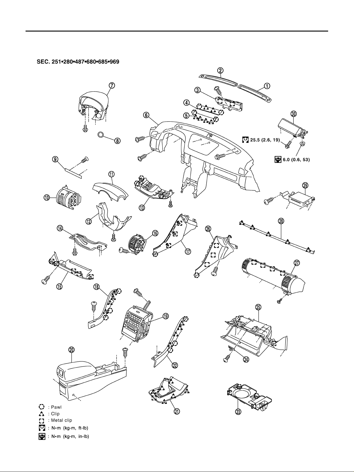
INSTRUMENT PANEL ASSEMBLY PFP:68200 Component Parts Drawing AIS000B8
PIIB2701E
Edition; 2004 September 2005 G35 Sedan
IP-10
Page 11

INSTRUMENT PANEL ASSEMBLY
1. Front defroster grille (RH) 2. Front defroster grille (LH) 3. Display unit & amplifier
4. Cluster lid finisher upper 5. Cluster lid finisher lower 6. Instrument panel & pad
7. Cluster lid A 8. Steering lock escutcheon 9. Instrument finisher A
10. Side ventilator grille (LH) 11. Steering column cover upper 12. Steering column cover lower
13. Steering column cover front lower 14. Knee protector lower 15. Instrument driver lower panel
16. Center ventilator grille (LH) 17. Instrument side panel (LH) 18. Cluster lid C side finisher (LH)
19. Cluster lid C assembly 20. Center console assembly 21. Console finisher
22. Cluster lid C side finisher (RH) 23. Instrument lower cover 24. Glove box striker
25. Glove box assembly 26. Instrument side panel (RH) 27. Center box assembly
28. Instrument finisher B 29. NAVI control unit 30. Passenger air bag module
Removal and Installation AIS000B9
WORK STEP
When removing instrument panel and pad, combination meter, audio and display, NAVI control unit and center
console, take steps in the order shown by the numbers below.
Refer-
Parts
A Selector knob (A/T models) AT-235
B Shift knob (M/T models) MT-13
C Console finisher (A/T models) IP-12
D Console boot (M/T models) IP-12
E Cluster lid C side finish er (RH/ LH ) IP-12
F Cluster lid finisher upper IP-12
G Cluster lid finisher lower IP-13
H Instrument finisher B IP-13
I Cluster lid C side finisher (RH/LH) IP-13
J Instrument lower driver panel IP-13
K Steering column covers IP-13
L Ligting &tur n signal sw itch LT-129
M Wiper & washer switch WW-35
N Knee protector lower IP-14
O Steering lock escutcheon IP-14
P Cluster lid A IP-14
Q Front kicking plate(RH/LH) EI-39
R Dush side finisher(RH/LH) EI-39
S Instrum ent lower cover IP-14
T Glove box assembly IP-14
U Instrument side panel (RH/LH) IP-15
V Center box assembly IP-15
W NAVI control unit AV-98
X Passenge r air bag module SRS-46
Y Center console assembly IP-15
Z Display unit &lifier ATC-120
Aa Front defroster grille (RH/LH) ATC-136
Ab Side vetilator grille (LH) ATC-136
Ac Center ventilator grille (LH) ATC-136
ence
page
Instrument
panel &
pad
11 1 1
11 1 1
22 2 2
22 2 2
33 3 3
44
55
66 4
77
81
92
10 3
11 4
12 5
13 6
14 7
15 1 5
16 2 6
17 3 7
18 4 8
19 9
20 10
21
22
23
24
25
26
27
Cluster lid CCluster lid
A
Center
console
assembly
Glove box
assembly
Center box
assembly
A
B
C
D
E
F
G
H
IP
J
K
L
M
Edition; 2004 September 2005 G35 Sedan
IP-11
Page 12
INSTRUMENT PANEL ASSEMBLY
Refer-
Parts
Ad Front pillar garnish EI-39 28
Ae Instrument panel & pad IP-16
ence
page
Instrument
panel &
pad
29
Cluster lid CCluster lid
A
Center
console
assembly
REMOVAL
(A) Selector lever Knob (A/T Models)
Remove selector l ever knob. Rfer to AT-235, "Control Device Removal and Installation" .
(B) Shift Knob (M/T Models)
Remove shift knob. Refer to MT-13, "SHIFT CONTROL" .
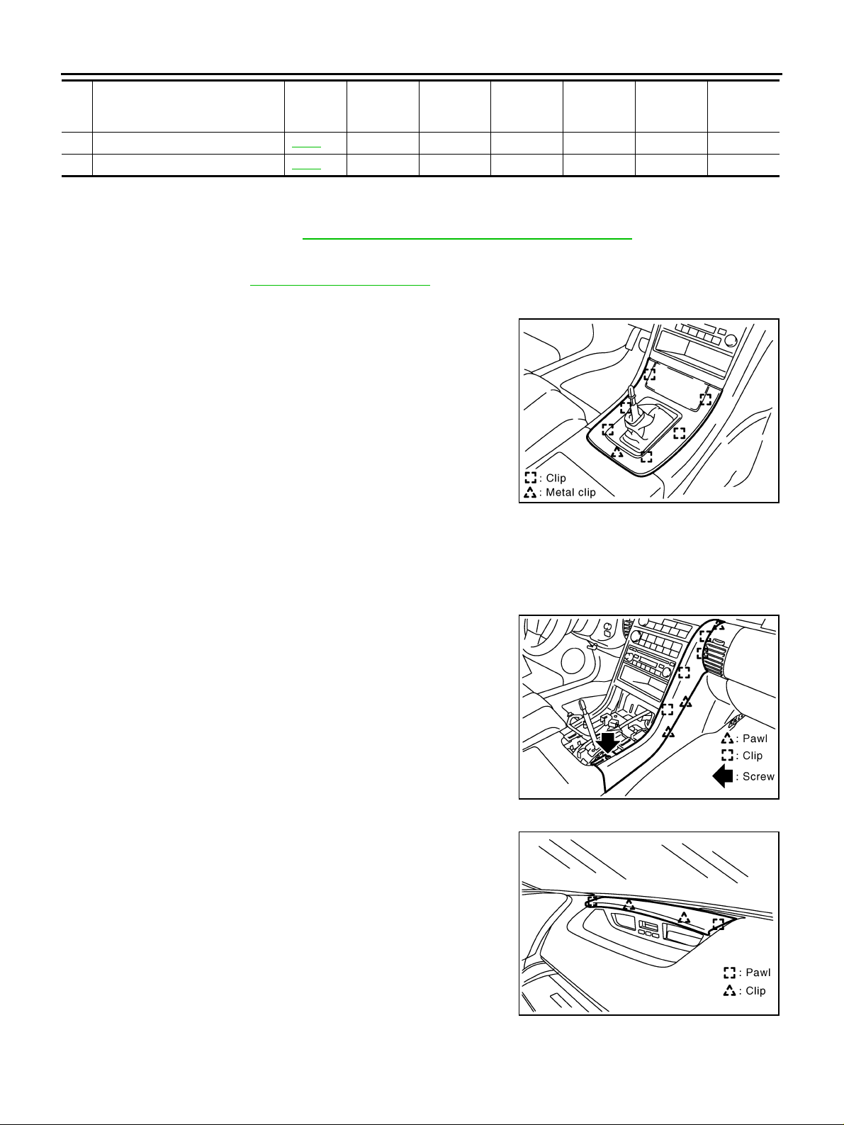
(C) Console Finisher (A/T Models)
1. Put selector lever in drive position.
2. Remove clips from rear of console finisher, then remove clips at
front. Pull console finisher upward to disengage from console.
CAUTION:
Guide pin inserted in to A/T device gu ide can be easily broken. Be careful when removing it.
3. Disconnect harness connectors, and remove console finisher.
4. After removing, remove each parts from console finisher.
Glove box
assembly
Center bo x
assembly
PIIB2702E
(D) Console Boot (M/T Models)
1. Insert a thin flat-bladed screwdriver wrapped with tape from behind console boot, and remove metal clip
on back. Then pull up and back to disengage from front metal clip.
2. Disvonnect hazard switch harness connector, and remove console boot.
(E) Cluster Lid C Side Finish er (RH/LH)
1. Remove screws.
2. Disconnect pawls, and remove cluster lid C side finisher.
PIIB2703E
(F) Cluster Lid Finisher Up per
Pull to the bac k si de , d is co nn ec t c li ps and pawls, and remo v e cluster
lid finisher upper.
PIIB2704E
Edition; 2004 September 2005 G35 Sedan
IP-12
Page 13
INSTRUMENT PANEL ASSEMBLY
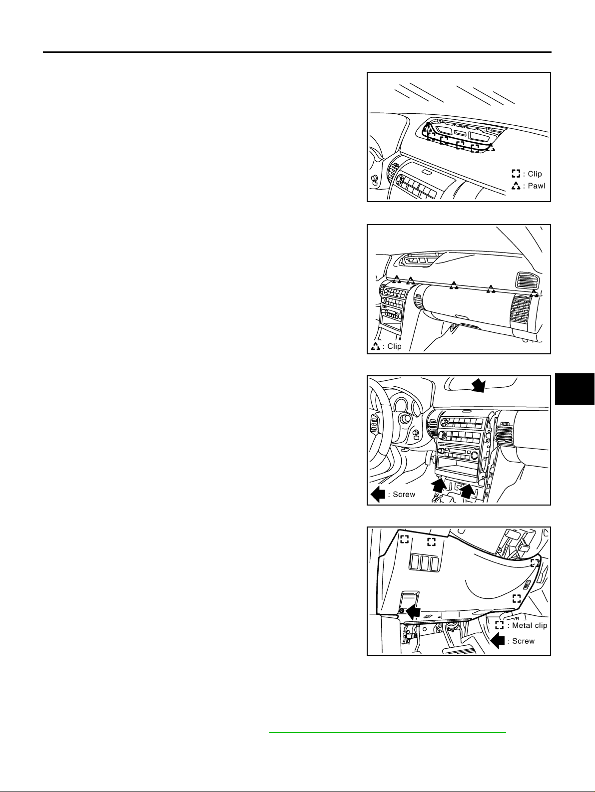
(G) Cluster Lid Finisher Lower
Disconnect pawls and clips, and remove cl uster lid finisher lower.
A
B
C
(H) Instrument Finisher B
Disconnect cli ps, and remove instrument finisher B.
(I) Cluster Lid C
1. Remove screws.
2. Disconnect harness connector of display unit and audio unit,
and remove it.
PIIB2705E
PIIB2706E
D
E
F
G
H
IP
J
K
PIIB2707E
(J) Instrument Lower Driver Panel
1. Remove screws.
2. Pull back to your side , d is co nnect me t al cl ips and remove in str ument lower driver panel.
3. Disconnect in-vehicle sensor and each electrical parts connectors.
4. Remove grommet, and remove hood lock cable.
PIIB2708E
(K) Steering Column Covers
1. Remove screws and pawls and remove steering column cover front lower.
2. Disconnect pawls, and remove upper and lower side of steering col umn covers.
(L) Lighting and Turn Signal Switch
Remove light ing and turn signal switch. Refer to LT-129, "LIGHTING AND TURN SIGNAL SWITCH" .
Edition; 2004 September 2005 G35 Sedan
IP-13
L
M
Page 14
INSTRUMENT PANEL ASSEMBLY
(M) Wiper and Washer Switch
Remove wiper an d washer switch. Refer to WW-35, "Removal and Installation of Front Wiper and Washer
Switch"
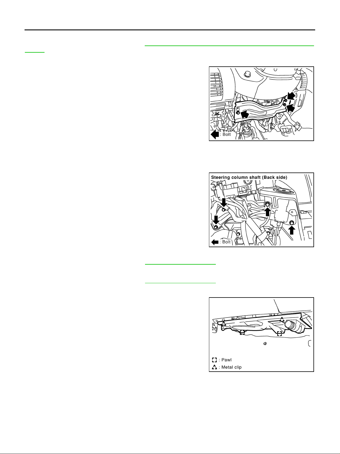
(N) Knee Protector Lower
Remove bolts and then remove knee protector.
PIIB2718E
(O) Steering Lock Escutcheon
Pull back to your side, and remove steering lock escutcheon.
(P) Cluster Lid A
After removing bolts, disconnect harness connectors of combination
meter and mirror control switch, and remove cluster lid A.
(Q) Front Kicking Plate (RH/LH)
Remove front kicking plate (RH/LH). Refer to EI-39, "BODY SIDE TRIM" .
(R) Dash Side Finisher (RH/LH)
Remove dash side finisher (RH/LH). Refer to EI-39, "BODY SIDE TRIM" .
(S) Instrument Lower Cover
Pull downward, dis co nn ect metal clips , and r emo ve instr u ment lowe r
cover.
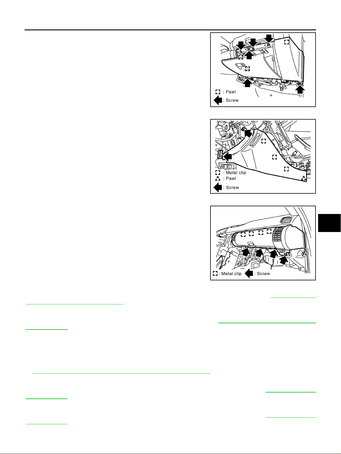
(T) Glove Box Assembly
1. Remove screws with power tool.
PIIA1241E
PIIB2709E
Edition; 2004 September 2005 G35 Sedan
IP-14
Page 15
INSTRUMENT PANEL ASSEMBLY
2. Pull back to your side, and disconnect clips, and remove glove
box assembly.
(U) Instrument Side Panel (RH/LH)
1. Remove screws.
2. Pull to the s ide, disconnect metal cli ps and harness connector,
and remove instrument side panel (RH/LH).
A
B
C
PIIB2710E
D
E
F
G
PIIB2711E
(V) Center Box Assembly
1. Remove screws.
2. Hold left side of center box assembly, pull to outside of vehicle
and disconnect metal clips. Remove center box assembly.
PIIB2712E
(W) NAVI Control Unit
Remove screws, a nd dis c on ne ct harn es s co nn ec tor, and remove N AVI control unit. Refer to AV -98, "Removal
and Installation of NAVI Control Unit" .
(X) Passenger Air Bag Module
Remove bolts and nut s , and remove passenger air bag module. Refer to SRS-46, "FRONT PASSENGER AIR
BAG MODULE" .
(Y) Center Console
Remove screws and remove center console.
H
IP
J
K
L
M
(Z) Display unit and Amplifier Assembly
Remove screws , and disconnec t h arn es s connector, and remove aud io d is play and amplifi er as sembly. Refer
to ATC-120, "
Removal and Installati on of Display and A/C Auto Amp." .
(Aa) Front Defroster Grille (RH/LH)
Disconnect pawls with screwdriver wrapped in cloth and remove defroster grille. Refer to ATC-136, "DUCTS
AND GRILLES" .
(Ab) Side Ventilator Grille (LH)
Pull back to your side, dis connect metal clips and remove side vent ilator grille. Refer to ATC-136, "DUCTS
AND GRILLES" .
Edition; 2004 September 2005 G35 Sedan
IP-15
Page 16

INSTRUMENT PANEL ASSEMBLY
(Ac) Center Ventilator Grille (LH)
Pull back to your side, disconnect metal clips and remove center ventilator grille. Refer to ATC-136, "DUCTS
AND GRILLES" .
(Ad) Front Pillar Garnish (RH/LH)
Pull to inside of vehicle, disconnect metal clips and remove front pillar garnish. Refer to EI-39, "BODY SIDE
TRIM" .
(Ae) Instrument Panel and Pad
1. Lower steering column.
2. Remove bolts and screws, and remove instrument panel and pad from passenger door opening portion.
INSTALLATION
Install in the reverse order of removal.
Edition; 2004 September 2005 G35 Sedan
IP-16
Page 17
INSTRUMENT PANEL ASSEMBLY
Disassembly and Assembly AIS000BB
CLUSTER LID A
A
B
C
D
E
F
G
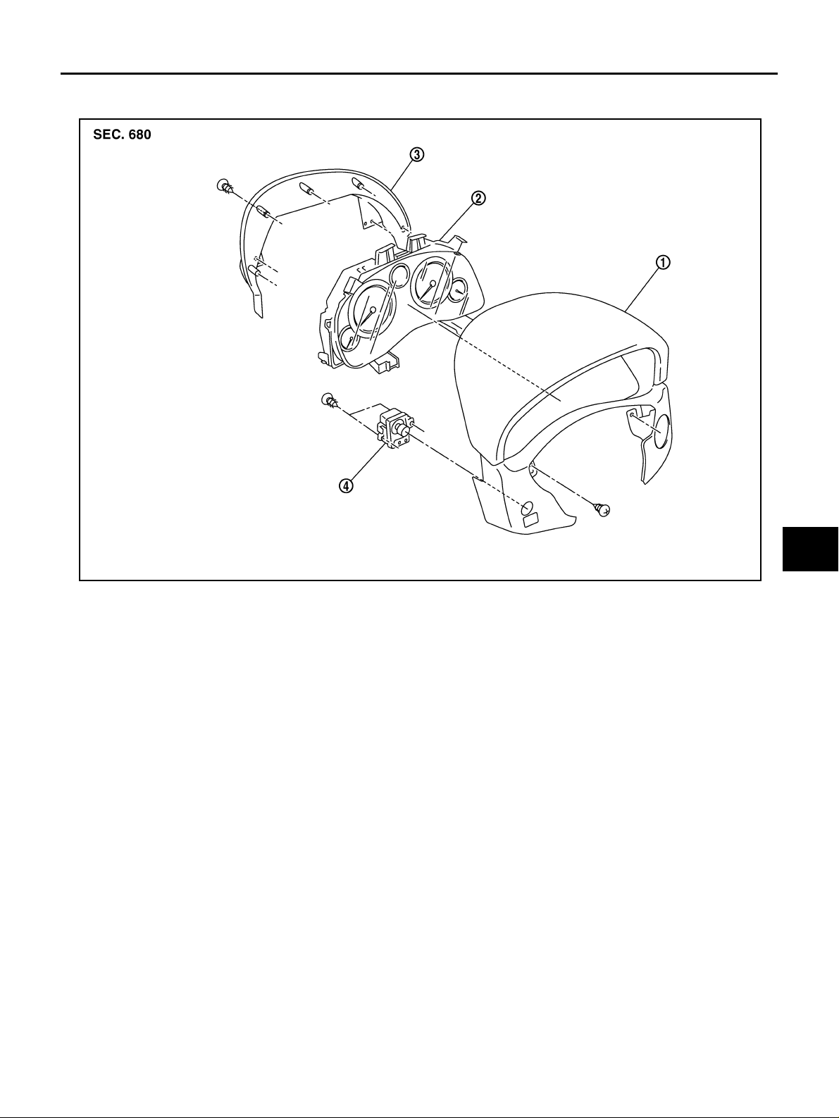
1. Cluster lid A 2. C om bi nation meter 3. Cluster lid A cover
4. Mirror control switch
Disassembly
1. Remove screws, and t hen remove mirror control switch.
2. Remove screws, and then remove cluster lid A cover.
3. Remove screws, and then remove combination meter.
Assembly
Assemble in th e reverse order o f disassembly.
H
IP
PIIB2713E
J
K
L
M
Edition; 2004 September 2005 G35 Sedan
IP-17
Page 18
CLUSTER LID C
INSTRUMENT PANEL ASSEMBLY
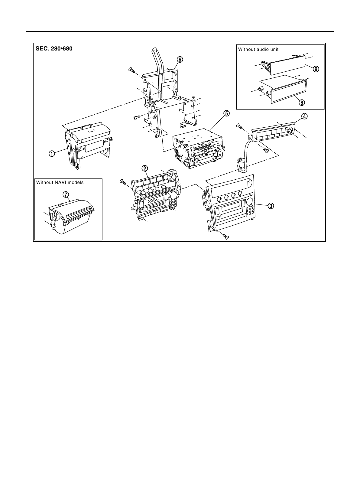
1. Display unit assembly 2. Control panel assembly 3. Cluster lid C
4. AV&NAVI SW 5. Audio assembly 6. Audio bracket
7. Instrument upper pocket 8. Pcket deck 9. Instrument mask
Disassembly
1. Remove cluster lid C panel.
2. Remove AV & NAVI switch.
3. Remove control panel assembly.
4. Remove display unit.
5. Remove instr ument upper pocket (without NAVI models).
6. Remove audio assembly.
7. Remove instrument mask (without audio models).
8. Remove pocket deck.
Assembly
Assemble in the reverse order of disassembly.
PIIB2717E
Edition; 2004 September 2005 G35 Sedan
IP-18
Page 19
INSTRUMENT PANEL ASSEMBLY
GLOVE BOX ASSEMBLY
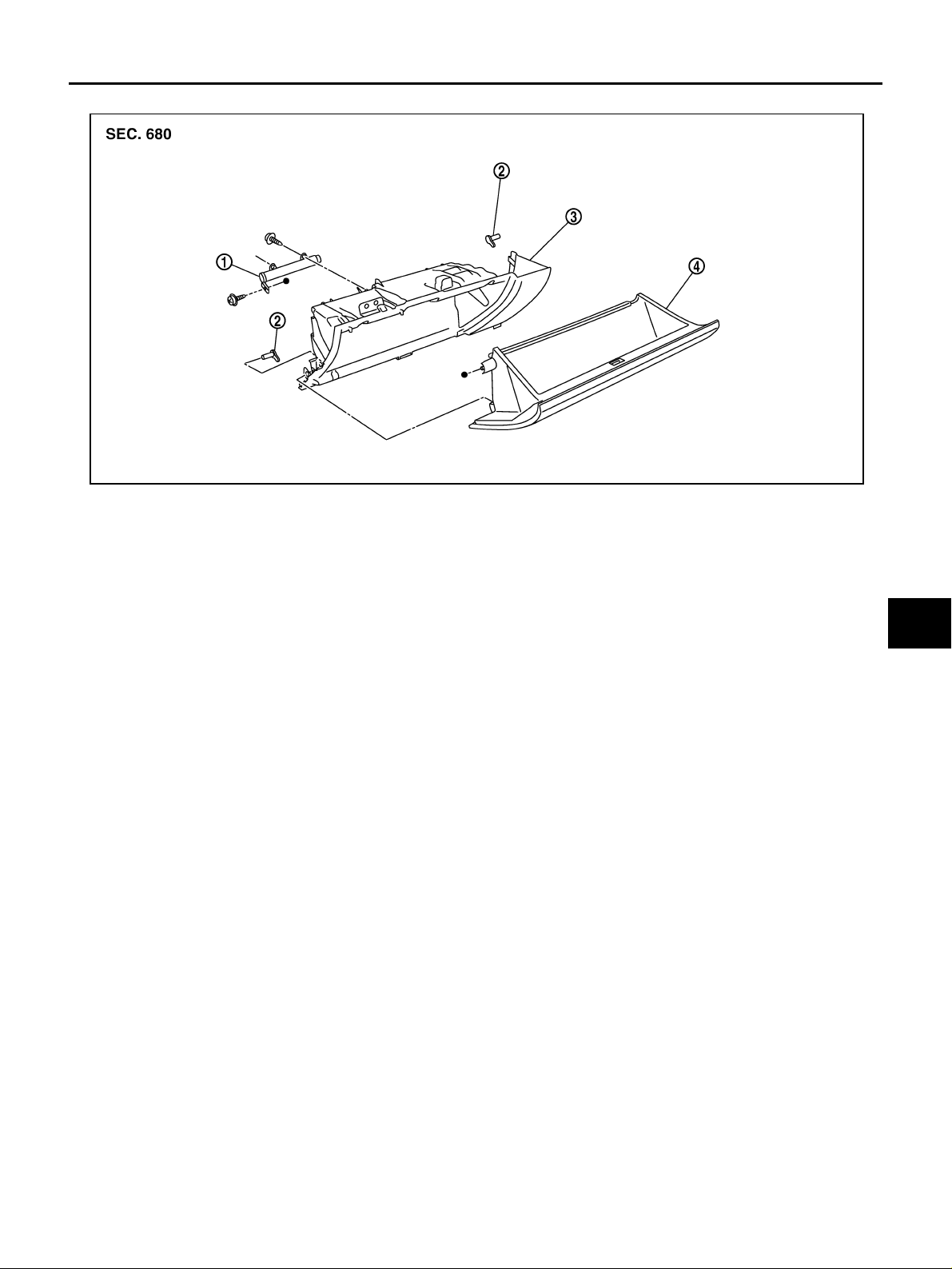
1. Damper 2. Pin 3. Instrument lower passenger panel
4. Glove box
A
B
C
D
E
F
PIIB2716E
G
Disassembly
1. Remove screws of damper wire portion.
2. Disconnect glove box pins, and remove glove box.
3. Remove screws on back side of instru ment lower pass enger panel, and remove damper.
Assembly
Assemble in th e reverse order o f disassembly.
H
IP
J
K
L
M
Edition; 2004 September 2005 G35 Sedan
IP-19
Page 20
INSTRUMENT PANEL ASSEMBLY
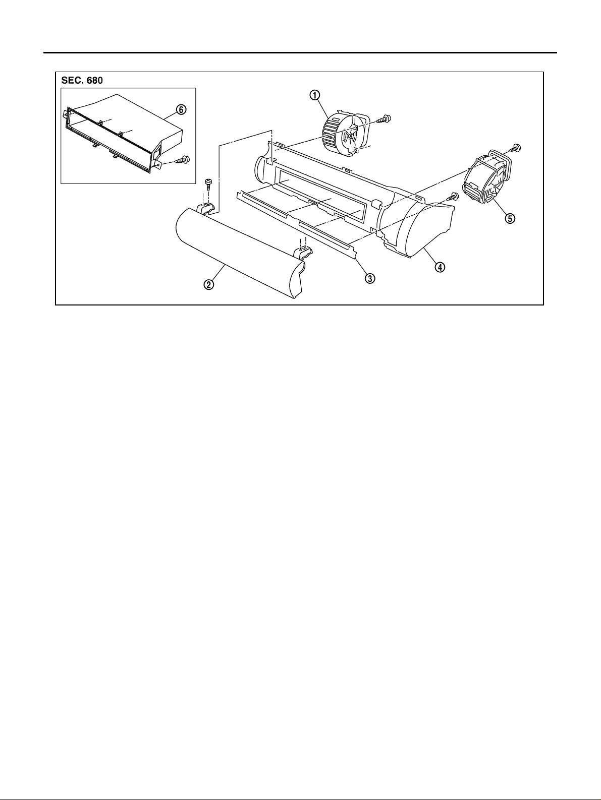
CENTER BOX ASSEMBLY
1. Center ventilator grille (RH) 2. Center box upper lid 3. Center box lower lid
4. Center box 5. Side ventilator grille (RH) 6. Pocket
PIIB2714E
Disassembly
1. Remove screw s and pawls, and then remove side ventilator gr ille (RH) and center ventilator grille.
2. Remove screws, and then remove NAVI control unit.
3. Remove screws, and then remove pocket (without NAVI models).
4. Remove screws, and then remove center box upper and lower lid.
Assembly
Assemble in the reverse order of disassembly.
Edition; 2004 September 2005 G35 Sedan
IP-20
Page 21
INSTRUMENT PANEL ASSEMBLY
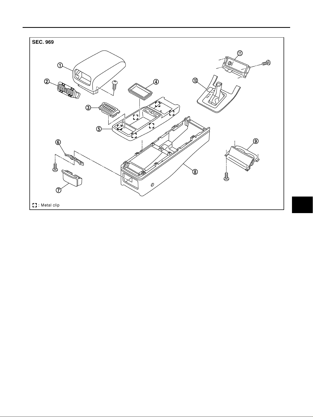
CENTER CONSOLE (A/T MODELS)
A
B
C
D
E
F
G
1. Console lid 2. Rear ventila tor gril le 3. Console mask
4. Console pocket 5. Console tray 6. Ashtray bracket
7. Ashtray (rear) 8. Center console 9. Cup holder
10. Console finisher 11. Ashtray (front)
Disassembly
1. Remove screws of back side (front), and remove ashtray (front portion).
2. Remove console mask.
3. Remove screws and remove console lid .
4. Disconnect metal clips and remove rear ventilator from console lid.
5. Remove ashtray.
6. Remove screws and remove ashtray bracket.
7. Disconnect metal clips (back side), and remove console tray.
8. Remove screws of back side (lower), and remove cup holder.
Assembly
Assemble in th e reverse order o f disassembly.
PIIB2715E
H
IP
J
K
L
M
Edition; 2004 September 2005 G35 Sedan
IP-21
Page 22
INSTRUMENT PANEL ASSEMBLY
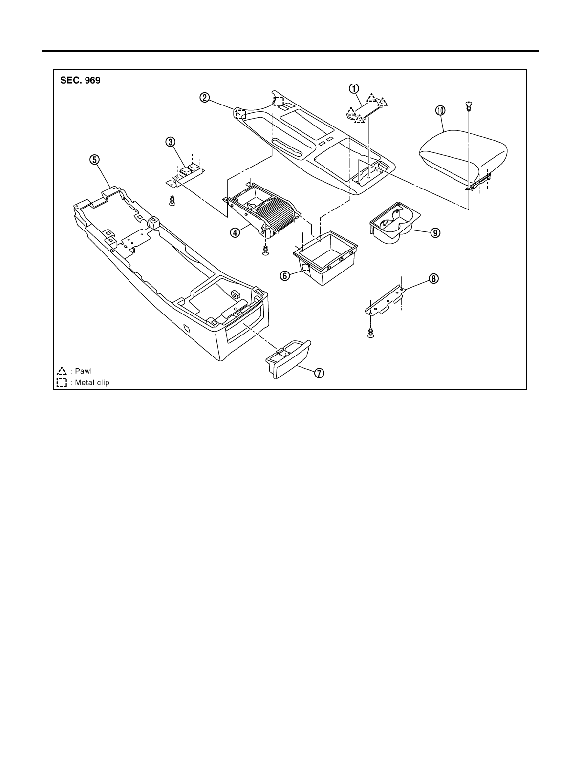
CENTER CONSOLE (M/T MODELS)
1. Console mask 2. Console tray 3. Switch bezel
4. Cup holder w/shutter 5. Console body 6. Console box
7. Ashtray (rear seat side) 8. Console bracket 9. Cup holder (de taching type)
10. Console lid
Disassembly
1. Remove console mask.
2. Remove screws and remove console lid.
3. Remove metal clips and remove console tray.
4. Remove ashtray.
5. Remove screws of back side, and remove switch bezel and cup holder w/shutter.
6. Remove screws of back side, and remove console bracket and consol e box.
Assembly
Assemble in the reverse order of disassembly.
PIIB3512E
Edition; 2004 September 2005 G35 Sedan
IP-22
 Loading...