

Page 1

DRIVER CONTROLS
2007 G35 Sedan
Revision: October 2006
A
B
SECTION INL
INTERIOR LIGHTING SYSTEM
CONTENTS
BASIC INSPECTION ....................................3
DIAGNOSIS AND REPAIR WORKFLOW ..........3
Work Flow .................................................................3
FUNCTION DIAGNOSIS ...............................6
INTERIOR ROOM LAMP CONTROL SYSTEM
.....
System Diagram ........................................................6
System Description ...................................................6
Component Parts Location . .......................................7
Component Description ......................... ...................8
INTERIOR ROOM LAMP BATTERY SAVER
SYSTEM ..............................................................
System Diagram ........................................................9
System Description ...................................................9
Component Parts Location . .......................................9
Component Description ......................... .................10
ILLUMINATION CONTROL SYSTEM ................11
System Diagram ......................................................11
System Description .................................................11
Component Parts Location . .....................................11
Component Description ...........................................12
DIAGNOSIS SYSTEM (BCM) ............................13
COMMON ITEM .........................................................13
COMMON ITEM : CONSULT-III Function (BCM -
COMMON ITEM) ....... ... ... ... .... ... ... ... ........................
INT LAMP ..................................................................13
INT LAMP : CONSULT-III Function (BCM - INT
LAMP) .....................................................................
BATTERY SAVER .....................................................15
BATTERY SAVER : CONSULT-III Function (BCM
- BATTERY SAVER) ...............................................
COMPONENT DIAGNOSIS .........................17
13
13
15
POWER SUPPLY AND GROUND CIRCUIT ....17
BCM ...........................................................................17
BCM : Diagnosis Procedure ....................................17
BCM : Special Repair Requirement .........................17
INTERIOR ROOM LAMP POWER SUPPLY
CIRCUIT ............................................................
6
Description .......................... ... ....... ...... ....... ...... ........18
Component Function Check ....................................18
Diagnosis Procedure ...............................................18
INTERIOR ROOM LAMP CONTROL CIRCUIT
Description .......................... ... ....... ...... ....... ...... ........20
9
Component Function Check ....................................20
Diagnosis Procedure ...............................................20
STEP LAMP CIRCUIT ....................................... 22
Description .......................... ... ....... ...... ....... ...... ........22
Component Function Check ....................................22
Diagnosis Procedure ...............................................22
TRUNK ROOM LAMP CIRCUIT .......................24
Description .......................... ... ....... ...... ....... ...... ........24
Component Function Check ....................................24
Diagnosis Procedure ...............................................24
PUSH-BUTTON IGNITION SWITCH ILLUMI-
NATION CIRCUIT .............................................
Description .......................... ... ....... ...... ....... ...... ........26
Component Function Check ....................................26
Diagnosis Procedure ...............................................26
INTERIOR ROOM LAMP CONTROL SYSTEM
Wiring Diagram —INTERIOR ROOM LAMP — ......28
ILLUMINATION .................................................36
Wiring Diagram —ILLUMINATION— ......................36
ECU DIAGNOSIS .........................................46
...
...
18
20
26
28
C
D
E
F
G
H
I
J
K
INL
M
N
O
P
INL-1
Page 2

BCM (BODY CONTROL MODULE) ..................46
2007 G35 Sedan
Revision: October 2006
Reference Value ..................... ... ... ... ....................... 46
Wiring Diagram — BCM — . .................................... 69
Fail Safe .............................................. ................... 74
DTC Inspection Priority Chart .............................. 76
DTC Index ........................................... ................... 77
COMBINATION METER ....................................80
Reference Value ..................... ... ... ... ....................... 80
Wiring Diagram — METER — ................................ 83
Fail Safe ................................................................. 92
DTC Index .............................................................. 93
SYMPTOM DIAGNOSIS ............................. 94
INTERIOR LIGHTING SYSTEM SYMPTOMS ...94
Symptom Table .................. .... ... ............................. 94
PRECAUTION ............................................. 95
Replacement .................... .......................................97
CIGARETTE LIGHTER ILLUMINATION ........... 98
Exploded View ........................................................98
Replacement .................... .......................................98
GLOVE BOX LAMP ........................................... 99
Exploded View ........................................................99
Replacement .................... .......................................99
STEP LAMP ......................................................100
Exploded View ...................................................... 100
Removal and Installation ....................................... 100
Replacement .................... ..................................... 100
PERSONAL LAMP ...........................................101
Exploded View ...................................................... 101
Removal and Installation ....................................... 101
Replacement .................... ..................................... 102
PRECAUTIONS .................................................95
Supplemental Restraint System (SRS) "AIR B
AG" and "SEAT BELT PRE-TENSIONER" .........
95
ON-VEHICLE REPAIR ................................ 96
MAP LAMP ........................................................ 96
Exploded View ........................... ... .......................... 96
Removal and Installation ........................................ 96
Replacement .......................................................... 96
VANITY MIRROR LAMP ................................... 97
Exploded View ........................... ... .......................... 97
TRUNK ROOM LAMP ......................................103
Exploded View ...................................................... 103
Removal and Installation ....................................... 103
Replacement .................... ..................................... 103
SERVICE DATA AND SPECIFICATIONS
(SDS) .........................................................104
SERVICE DATA AND SPECIFICATIONS
(SDS) ................................................................
Bulb Specifications ........ ... ... ... .... ... ... ... ... ............... 104
104
INL-2
Page 3
< BASIC INSPECTION >
2007 G35 Sedan
Revision: October 2006
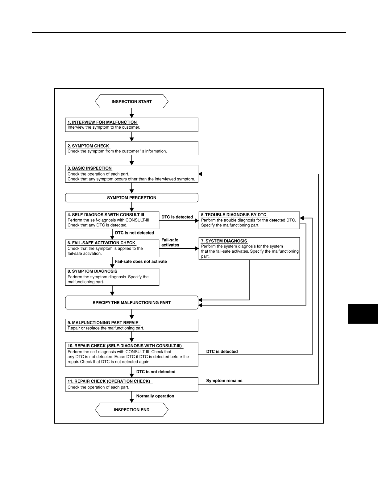
DIAGNOSIS AND REPAIR WORKFLOW
BASIC INSPECTION
DIAGNOSIS AND REPAIR WORKFLOW
Work Flow INFOID:0000000000962564
OVERALL SEQUENCE
A
B
C
D
E
F
G
H
JPLIA0089GB
I
J
K
INL
M
N
O
P
INL-3
Page 4

DIAGNOSIS AND REPAIR WORKFLOW
2007 G35 Sedan
Revision: October 2006
< BASIC INSPECTION >
DETAILED FLOW
1.INTERVIEW FOR MALFUNCTION
Interview the symptom to the customer.
>> GO TO 2.
2.SYMPTOM CHECK
Check the symptom from the customer's information.
>> GO TO 3.
3.BASIC INSPECTION
Check the operation of each part. Check that any symptom occurs other than the interviewed symptom.
>> GO TO 4.
4.SELF-DIAGNOSIS WITH CONSULT-III
Perform the self-diagnosis with CONSULT-III. Check that any DTC is detected.
Is any DTC detected?
YES >> GO TO 5.
NO >> GO TO 6.
5.TROUBLE DIAGNOSIS BY DTC
Perform the trouble diagnosis for the detected DTC. Specify the malfunctioning part.
>> GO TO 9.
6.FAI L - SAFE ACTIVATION CHECK
Check that the symptom is applied to the fail-safe activation.
Does the fail-safe activate?
YES >> GO TO 7.
NO >> GO TO 8.
7.SYSTEM DIAGNOSIS
Perform the system diagnosis for the system that the fail-safe activates. Specify the malfunctioning part.
>> GO TO 9.
8.SYMPTOM DIAGNOSIS
Perform the symptom diagnosis. Specify the malfunctioning part.
>> GO TO 9.
9.MALFUNCTION PART REPAIR
Repair or replace the malfunctioning part.
>> GO TO 11.
10.REPAIR CHECK (SELF-DIAGNOSIS WITH CONSULT-III)
Perform the self-diagnosis with CONSULT-III. Check that any DTC is not detected. Erase DTC if DTC is
detected before the repair. Check that DTC is not detected again.
Is any DTC detected?
YES >> GO TO 5.
INL-4
Page 5

DIAGNOSIS AND REPAIR WORKFLOW
2007 G35 Sedan
Revision: October 2006
< BASIC INSPECTION >
NO >> GO TO 11.
11.REPAIR CHECK (OPERATION CHECK)
Check the operation of each part.
Does it operate normally?
YES >> INSPECTION END
NO >> GO TO 3.
A
B
C
D
E
F
G
H
J
K
INL
M
N
O
I
P
INL-5
Page 6
INTERIOR ROOM LAMP CONTROL SYSTEM
2007 G35 Sedan
Revision: October 2006
< FUNCTION DIAGNOSIS >
FUNCTION DIAGNOSIS
INTERIOR ROOM LAMP CONTROL SYSTEM
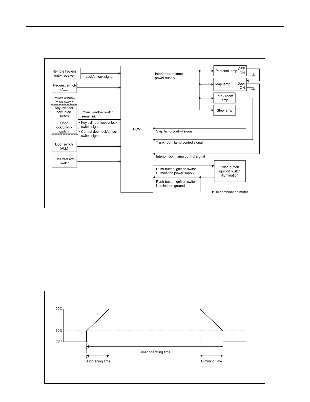
System Diagram INFOID:0000000000962565
JPLIA0090GB
System Description INFOID:0000000000962566
OUTLINE
• Interior room lamps* are controlled by interior room lamp timer control function of BCM.
*: Map lamp and personal lamp (when map lamp switch is in DOOR position).
• Trunk room lamp is controlled by trunk room lamp control function of BCM.
• Step lamp is controlled by step lamp control function of BCM.
• Push-button ignition switch illumination is controlled by the push-button ignition switch illumination control
function of BCM.
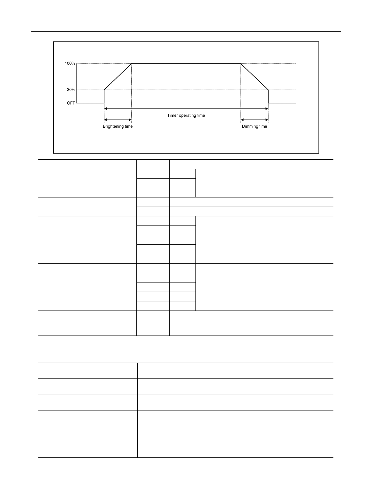
INTERIOR ROOM LAMP TIMER CONTROL
Interior Room Lamp Timer Basic Operation
JPLIA0093GB
INL-6
Page 7

INTERIOR ROOM LAMP CONTROL SYSTEM
2007 G35 Sedan
Revision: October 2006
< FUNCTION DIAGNOSIS >
• The interior room lamp turns ON and OFF (gradual brightening and dimming) by the interior room timer.
• BCM judges the vehicle condition with the following items. It activates the interior room timer.
- Ignition switch status
- Door switch signal (ALL)
- Door lock/unlock signal (Remote keyless entry receiver, each request switch, key cylinder lock/unlock
switch, central door lock/unlock switch)
NOTE:
Each function of interior room lamp timer can be set by CONSULT-III. Refer to INL-13, "
SULT-III Function (BCM - INT LAMP)".
Interior Room Lamp ON Operation
• BCM always turns the interior room lamp ON when any door opens.
• BCM activates the interior room timer in any of the following conditions to turn the interior room lamp ON for
a period of time.
- Any door opens before all doors close.
- Ignition switch is turned ON → OFF.
- Any door unlock signal is detected when all doors close with ignition switch OFF.
NOTE:
Restart the timer if new condition is input during the timer operating time.
Interior Room Lamp OFF Operation
BCM stops the timer in any of the following conditions to turns the interior room lamp OFF.
• The timer operating time is expired.
• Ignition switch position is other than OFF with all doors close.
• Any door lock operation is detected with all doors close.
INT LAMP : CON-
A
B
C
D
E
F
G
TRUNK ROOM LAMP CONTROL
BCM controls the trunk room lamp (ground-side) to turn ON with the trunk room lamp switch ON.
STEP LAMP CONTROL
BCM controls the step lamp (ground-side) to turn ON with any door switch ON.
PUSH-BUTTON IGNITION SWITCH ILLUMINATION CONTROL
Push-button Ignition Switch Illumination Basic Operation
• BCM provides the power supply and the ground to turn the push-button ignition switch illumination ON.
• BCM cuts the ground supply while the each illumination (tail lamp) ON. BCM switches to the ground control
with the meter illumination control function.
Push-button Ignition Switch Illumination ON Operation
BCM turns the push-button ignition switch illumination ON in the following conditions.
• Ignition switch ON
• Each illumination (tail lamp) ON
• Any of the following conditions with ignition switch OFF
- Engine start permission is entered.
- Intelligent Key inserted into the key slot.
- Driver door is LOCK → UNLOCK.
- Driver door is open.
Push-button Ignition Switch Illumination OFF Operation
BCM turns the push-button ignition switch illumination OFF in any of the following conditions.
• The push-button ignition switch illumination ON conditions do not satisfy.
• All of the following conditions with ignition switch OFF
- Each illumination (tail lamp) OFF
- The push-button ignition switch illumination ON conditions do not change (15 seconds after the ignition
switch OFF) or the driver door is UNLOCK → LOCK.
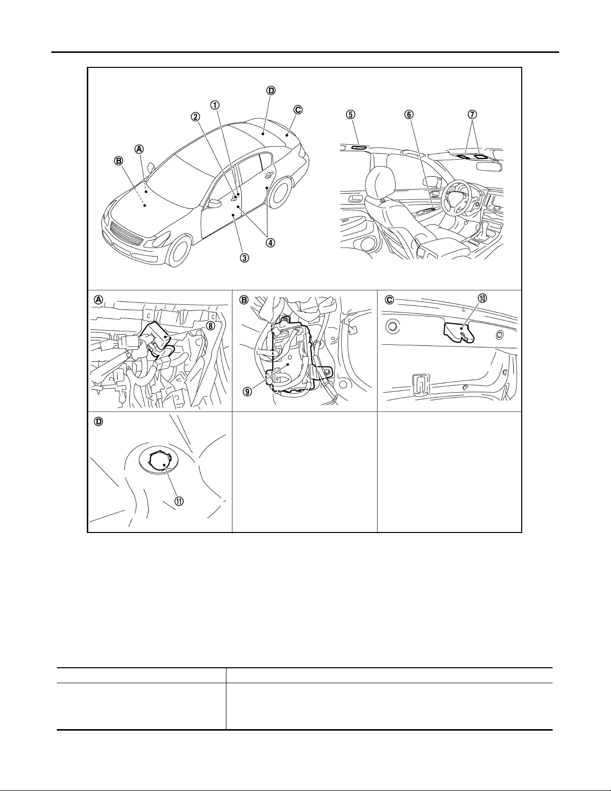
Component Parts Location INFOID:0000000000962567
H
I
J
K
INL
M
N
O
P
INL-7
Page 8
INTERIOR ROOM LAMP CONTROL SYSTEM
2007 G35 Sedan
Revision: October 2006
< FUNCTION DIAGNOSIS >
1. Key cylinder switch 2. Request switch 3. Step lamp
4. Door switch 5. Personal lamp 6. Central door lock switch
7. Map lamp 8. Remote keyless entry receiver 9. BCM
10. Trunk room lamp switch 11. Trunk room lamp
A. Behind glove box B. Dash side finisher (Passenger side) C . Trunk lid lock assembly
D. Trunk room upward
Component Description
BCM
JPLIA0038ZZ
INFOID:0000000000962568
Part Description
• Activates the interior room lamp tim er depending on the vehicle co ndition to tu rn the
interior room lamp ON/OFF.
• Turns the trunk room lamp ON /OF F according to the trunk roo m lamp switch st atus.
• Turns the step lamp ON /OFF according to any door switch status.
INL-8
Page 9
INTERIOR ROOM LAMP BATTERY SAVER SYSTEM
2007 G35 Sedan
Revision: October 2006
< FUNCTION DIAGNOSIS >
INTERIOR ROOM LAMP BATTERY SAVER SYSTEM
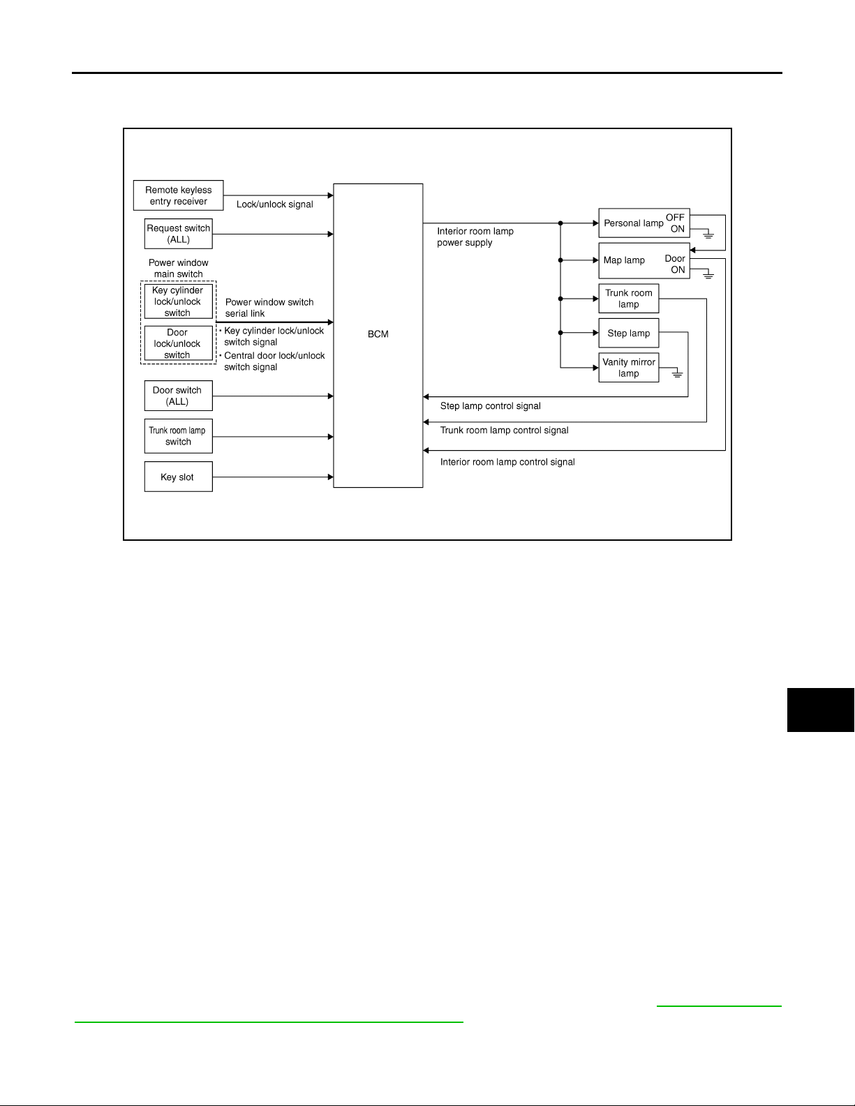
System Diagram INFOID:0000000000962569
A
B
C
D
E
F
G
H
JPLIA0091GB
System Description INFOID:0000000000962570
OUTLINE
• Interior room lamp battery saver is controlled by BCM.
• BCM turns applicable lamps OFF depending on the vehicle condition. This function prevents the battery
from over-discharging if the driver neglect turning OFF the any lamps.
Applicable lamps
• Map lamp
• Personal lamp
• Step lamp
• Trunk room lamp
• Vanity mirror lamp
INTERIOR ROOM LAMP BATTERY SAVER FANCTION
• When the ignition switch is turned OFF, BCM operates the timer for a period of time to cut the interior room
lamp power supply.
• BCM restart the timer when any of the following signals changes while operating the timer.
- Ignition switch status
- Door switch signal (ALL)
- Door lock/unlock signal (Remote keyless entry receiver, each request switch, key cylinder lock/unlock
switch, central door lock/unlock switch)
- Trunk loom lamp switch signal
- Key switch signal (Key slot)
• BCM provides the interior room lamp power supply continuously when the ignition switch position is other
than OFF.
NOTE:
Each function of interior room lamp battery saver can be set by CONSULT-III Refer to INL-15, "
SAVER : CONSULT-III Function (BCM - BATTERY SAVER)".
BATTERY
I
J
K
INL
M
N
O
P
Component Parts Location INFOID:0000000000962571
INL-9
Page 10
INTERIOR ROOM LAMP BATTERY SAVER SYSTEM
2007 G35 Sedan
Revision: October 2006
< FUNCTION DIAGNOSIS >
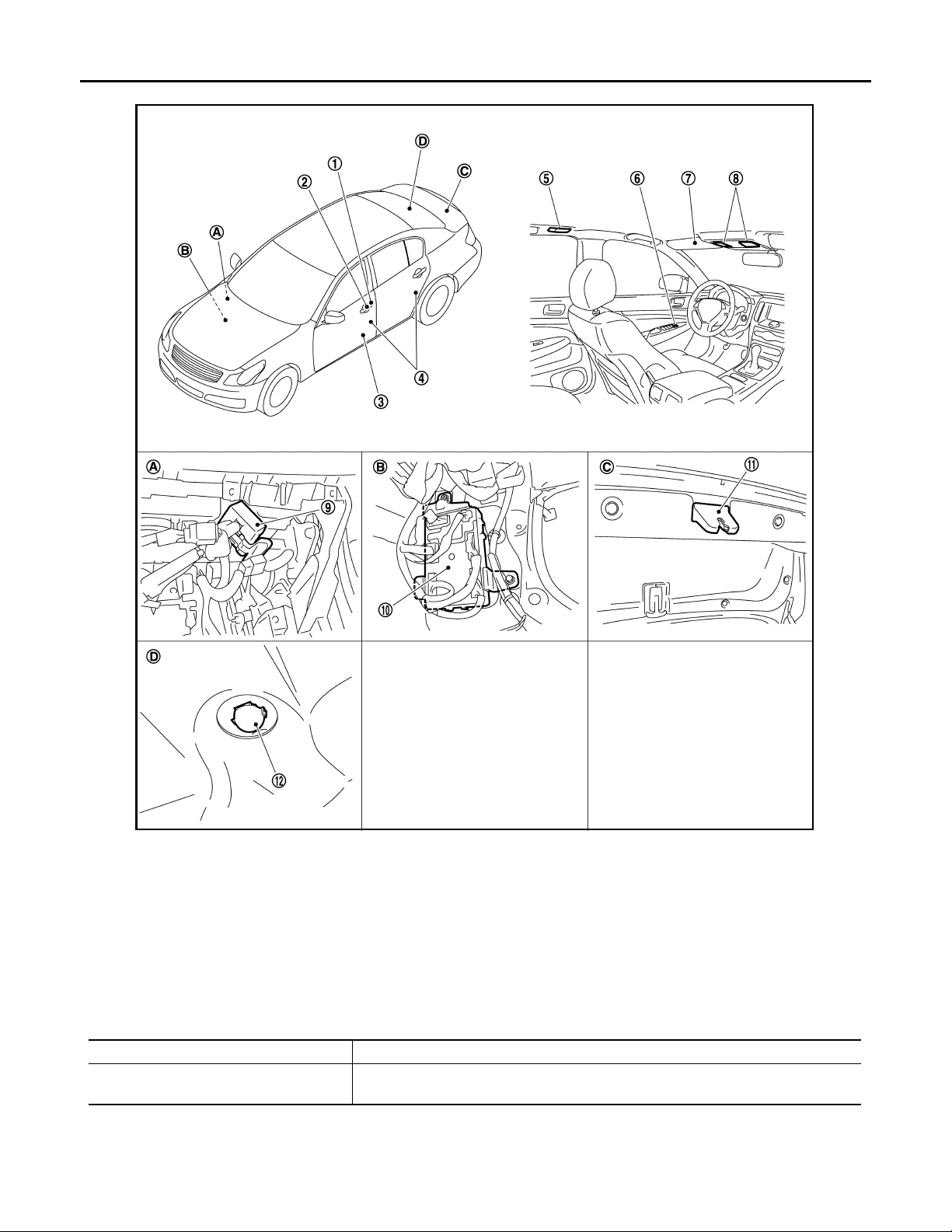
1. Key cylinder switch 2. Request switch 3. Step lam p
4. Door switch 5. Personal lamp 6. Central door lock switch
7. Vanity mirror lamp 8. Map lamp 9. Remote keyless entry rec eiv er
10. BCM 11. Trunk room lamp switch 12. Trunk room lamp
A. Behind glove box B. Dash side finisher (Passenger side) C. Trunk lid lock assembly
D. Trunk room upward
Component Description
BCM
JPLIA0039ZZ
INFOID:0000000000962572
Part Description
Operates the interior room lamp battery saver depending on the vehicle condition to
cut the interior room lamp power supply.
INL-10
Page 11
< FUNCTION DIAGNOSIS >
2007 G35 Sedan
Revision: October 2006
ILLUMINATION CONTROL SYSTEM
ILLUMINATION CONTROL SYSTEM
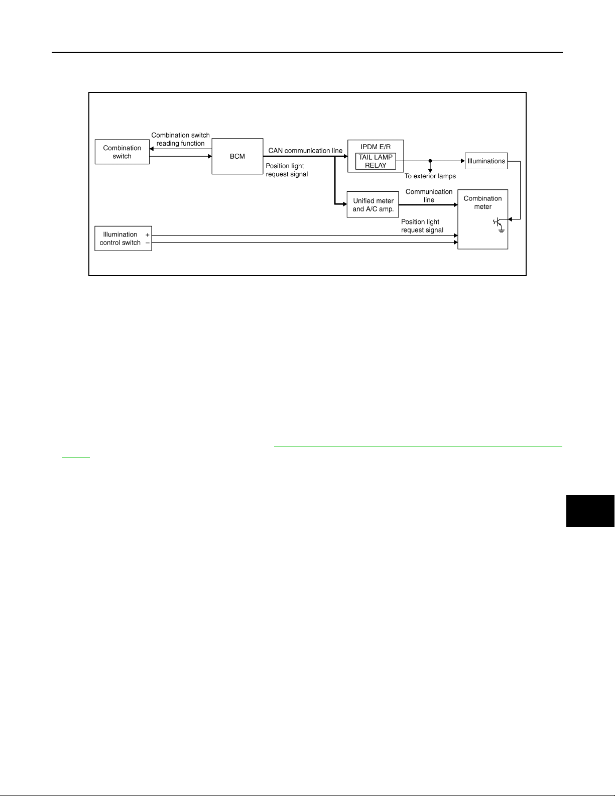
System Diagram INFOID:0000000000962573
JPLIA0092GB
System Description INFOID:0000000000962574
OUTLINE
Each illumination lamp is controlled by each function of BCM, IPDM E/R and combination meter.
Control by BCM
• Combination switch reading function
• Headlamp control function
Control by IPDM E/R
• Relay control function
A
B
C
D
E
F
G
H
I
Control by combination meter
• Meter illumination control function (Refer to MWI-24, "METER ILLUMINATION CONTROL : System Dia-
gram".)
ILLUMINATION CONTROL
• BCM detects the combination switch condition by the combination switch reading function.
• BCM transmits position light request signal to IPDM E/R and combination meter (through the unified meter
and A/C amp.) according to tail lamp ON condition.
Ta il lamp ON condition
- Lighting switch 1ST
- Lighting switch 2ND
- Lighting switch AUTO, and the auto light function ON judgment (With auto light system)
• IPDM E/R turns the integrated tail lamp relay ON according to position light request signal. It provides the
power supply to each illumination lamp.
• Combination meter enters in the nighttime mode according to position light request signal. Under the nighttime mode the combination meter controls the illuminance by controlling the each illumination lamp (ground
side).
Component Parts Location INFOID:0000000000962575
J
K
INL
M
N
O
P
INL-11
Page 12
< FUNCTION DIAGNOSIS >
2007 G35 Sedan
Revision: October 2006
ILLUMINATION CONTROL SYSTEM
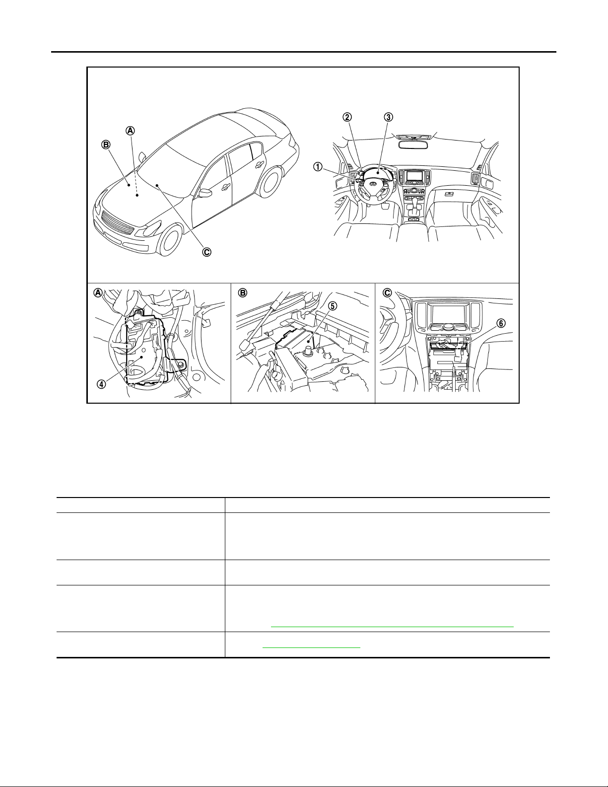
1. Combination switch 2. Illumination control switch 3. Combination meter
4. BCM 5. IPDM E/R 6. Unified meter and A/C amp.
A Dash side finisher (Passenger side) B. Engine room dash panel (RH) C. Behind cluster lid C
Component Description
Part Description
• Judges each switch condition by the combination switch reading function.
BCM
IPDM E/R
COMBINATION METETR
Combination switch
(Lighting & turn signal switch)
• Judges the illumination lamp ON/OFF status depending on the vehicle condition.
And then it transmits position light request signal to IPDM E/R and combination
meter (through the unified meter and A/C amp.) (with CAN communication).
Controls the integrated relay acc ord ing to the re ques t fr om BCM (wi t h CAN co mm un ication).
• Enters in nighttime mode according to the request from BCM (with CAN communication).
• Controls the each illumination in the nighttime mode.
Refer to MWI-24, "
Refer to BCS-5, "
METER ILLUMINATION CONTROL : System Diagram".
System Diagram".
JPLIA0040ZZ
INFOID:0000000000962576
INL-12
Page 13
< FUNCTION DIAGNOSIS >
2007 G35 Sedan
Revision: October 2006
DIAGNOSIS SYSTEM (BCM)
DIAGNOSIS SYSTEM (BCM)
COMMON ITEM
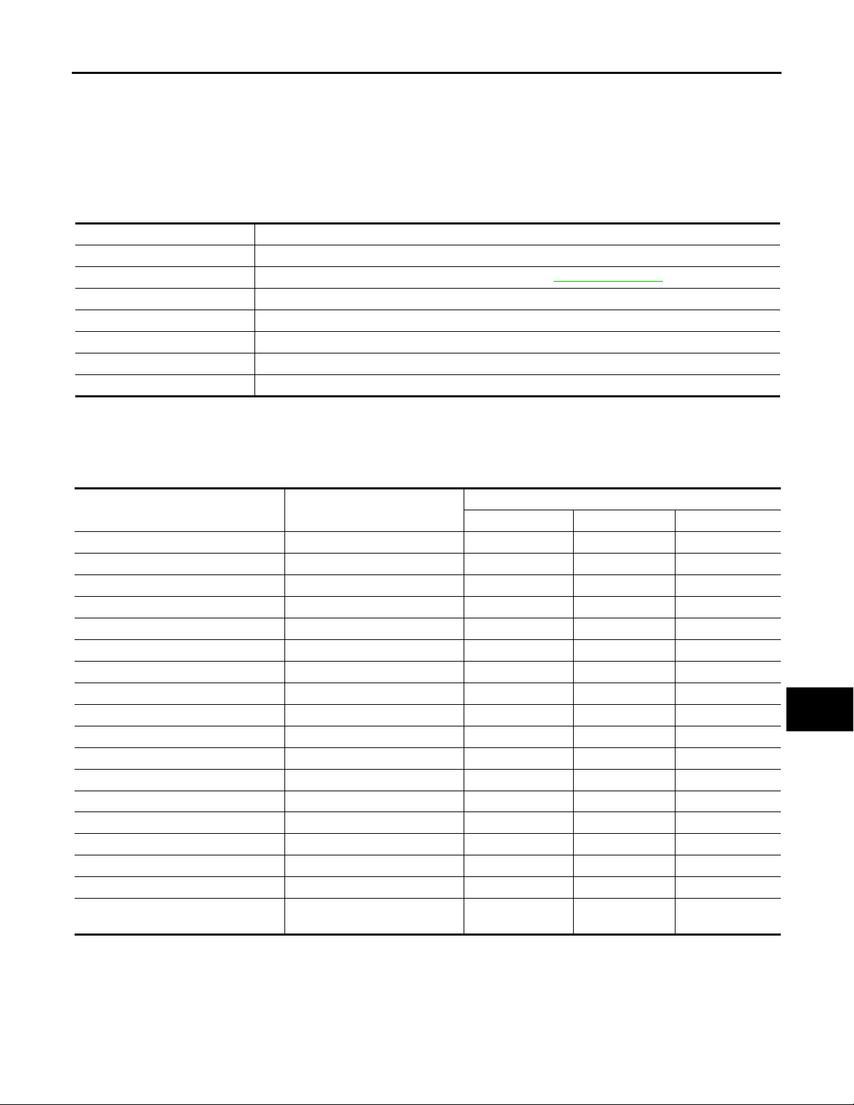
COMMON ITEM : CONSULT-III Function (BCM - COMMON ITEM) INFOID:0000000000962577
APPLICATION ITEM
CONSULT-III performs the following functions via CAN communication with BCM.
Diagnosis mode Function Description
WORK SUPPORT Changes the setting for each system function.
SELF-DIAG RESULTS Displays the diagnosis results judged by BCM. Refer to INL-77, "
CAN DIAG SUPPORT MNTR Monitors the reception status of CAN communication viewed from BCM.
DATA MONITOR The BCM input/output signals are displayed.
ACTIVE TEST The signals used to activate each device are forcibly supplied from BCM.
ECU IDENTIFICATION The BCM part number is displayed.
CONFIGURATION This function is not used even though it is displayed.
DTC Index".
SYSTEM APPLICATION
BCM can perform the following functions for each system.
NOTE:
It can perform the diagnosis modes except the following for all sub system selection items.
System Sub system selection item
Door lock DOOR LOCK ×××
Rear window defogger REAR DEFOGGER ××
Warning chime BUZZER ××
Interior room lamp timer INT LAMP ×××
Exterior lamp HEAD LAMP ×××
Wiper and washer WIPER ×××
Turn signal and hazard warning lamps FLASHER ×××
Air conditioner* AIR CONDITONER ×
Intelligent Key system INTELLIGENT KEY ×××
Combination switch COMB SW ×
BCM BCM ×
IVIS - NATS IMMU ××
Interior room lamp battery saver BATTERY SAVER ×××
Trunk open TRUNK ×
Vehicle security system THEFT ALM ×××
RAP system RETAINED PWR ×
Signal buffer system SIGNAL BUFFER ××
TPMS
*: This item is displayed, but is not used.
TPMS (AIR PRESSURE MONITOR)
WORK SUPPORT DATA MONITOR ACTIVE TEST
×××
Diagnosis mode
INT LAMP
A
B
C
D
E
F
G
H
J
K
INL
M
N
O
P
I
INT LAMP : CONSULT-III Function (BCM - INT LAMP) INFOID:0000000000962578
INL-13
Page 14
< FUNCTION DIAGNOSIS >
2007 G35 Sedan
Revision: October 2006
WORK SUPPORT
Service item Setting item Setting
ROOM LAMP TIMER SET
SET I/L D-UNLCK INTCON
ROOM LAMP ON TIME SET
ROOM LAMP OFF TIME SET
R LAMP TIMER LOGIC SET
*: Initial setting
DIAGNOSIS SYSTEM (BCM)
MODE 2 7.5 sec.
Sets the interior room lamp ON t ime. (T imer operating time)MODE 3* 15 sec.
MODE 4 30 sec.
ON* With the interior room lamp timer function
OFF Without the interior room lamp timer function
MODE 1 0.5 sec.
MODE 2* 1 sec.
MODE 3 2 sec.
MODE 4 3 sec.
MODE 5 0 sec.
MODE 1 0.5 sec.
MODE 2 1 sec.
MODE 3 2 sec.
MODE 4* 3 sec.
MODE 5 0 sec.
ON* Interior room lamp timer activates with synchronizing all doors.
OFF
Interior room lamp timer activates with synchronizing the driver door
only.
Sets the interior room lamp gradual brightening time.
Sets the interior room lamp gradual dimming time.
JPLIA0093GB
DATA MONITOR
REQ SW-DR
[ON/OFF]
REQ SW-AS
[ON/OFF]
PUSH SW
[ON/OFF]
ACC RLY-F/B
[ON/OFF]
KEY SW-SLOT
[ON/OFF]
Monitor item
[Unit]
Description
The switch status input from request switch (driver side)
The switch status input from front request switch (passenger side)
The switch status input from push-button ignition switch
ACC relay feedback signal status input from ACC relay
Key switch status input from key slot
INL-14
Page 15

< FUNCTION DIAGNOSIS >
2007 G35 Sedan
Revision: October 2006
DIAGNOSIS SYSTEM (BCM)
DOOR SW-DR
[ON/OFF]
DOOR SW-AS
[ON/OFF]
DOOR SW-RR
[ON/OFF]
DOOR SW- RL
[ON/OFF]
DOOR SW-BK
[ON/OFF]
CDL LOCK SW
[ON/OFF]
CDL UNLOCK SW
[ON/OFF]
KEY CYL LK-SW
[ON/OFF]
KEY CYL UN-SW
[ON/OFF]
TRNK/HAT MNTR
[ON/OFF]
RKE-LOCK
[ON/OFF]
RKE-UNLOCK
[ON/OFF]
ACTIVE TEST
Monitor item
[Unit]
Description
The switch status input from front door switch (driver side)
The switch status input from front door switch (passenger side)
The switch status input from rear door switch RH
The switch status input from rear door switch LH
NOTE:
The item is indicated, but not monitored.
Lock switch status received from central door lock switch by power window switch se-
rial link
Unlock switch status received from central door lock switch by powe r window swi tch
serial link
Lock switch status received from key cylinder switch by power window switch serial
link
Unlock switch status receiv ed from key cylinder sw itch by power window switch serial
link
The switch status input from trunk room lamp switch
Lock signal status received from remote keyless entry receiver
Unlock signal status received from remote keyless entry receiver
A
B
C
D
E
F
G
H
I
Test item Operation Description
Outputs the interior room lamp control signal to turn map lamp and personal lamp ON
(Map lamp switch is in DOOR position).
INT LAMP
STEP LAMP TEST
LUGGAGE LAMP TEST
ON
OFF Stops th e interio r room lamp c ontrol si gnal to tu rn map lamp and pers onal lam p OFF.
ON Outputs the step lamp control signal to turn step lamp ON.
OFF Stops the step lamp control signal to turn step lamp OFF.
ON Outputs the trunk room lamp control signal to turn step lamp ON.
OFF Stops the trunk room lamp control signal to turn step lamp ON.
BATTERY SAVER
BATTERY SAVER : CONSULT-III Function (BCM - BATTERY SA VER) INFOID:0000000000962579
WORK SUPPORT
Service item Setting item Setting
BATTERY SAVER SET
ROOM LAMP BAT SAV SET
ROOM LAMP TIMER SET
*: Initial setting
ON* With the exterior lamp battery saver function
OFF Without the exterior lamp battery saver function
ON* With the interior room lamp battery saver function
OFF Without the interior room lamp battery saver function
MODE 1* 30 min.
MODE 2 60 min.
Sets the interior room lamp battery saver timer operating
time.
J
K
INL
M
N
O
P
DATA MONITOR
INL-15
Page 16

< FUNCTION DIAGNOSIS >
2007 G35 Sedan
Revision: October 2006
DIAGNOSIS SYSTEM (BCM)
Monitor item
REQ SW-DR
[ON/OFF]
REQ SW-AS
[ON/OFF]
PUSH SW
[ON/OFF]
ACC RLY-F/B
[ON/OFF]
KEY SW-SLOT
[ON/OFF]
DOOR SW-DR
[ON/OFF]
DOOR SW-AS
[ON/OFF]
DOOR SW-RR
[ON/OFF]
DOOR SW- RL
[ON/OFF]
DOOR SW-BK
[ON/OFF]
CDL LOCK SW
[ON/OFF]
CDL UNLOCK SW
[ON/OFF]
KEY CYL LK-SW
[ON/OFF]
KEY CYL UN-SW
[ON/OFF]
TRNK/HAT MNTR
[ON/OFF]
RKE-LOCK
[ON/OFF]
RKE-UNLOCK
[ON/OFF]
[Unit]
Description
The switch status input from request switch (driver side)
The switch status input from front request switch (passenger side)
The switch status input from push-button ignition switch
ACC relay feedback signal status input from ACC relay
Key switch status input from key slot
The switch status input from front door switch (driver side)
The switch status input from front door switch (passenger side)
The switch status input from rear door switch RH
The switch status input from rear door switch LH
NOTE:
The item is indicated, but not monitored.
Lock switch status received from cent ral door lock switch by power wind ow switch se-
rial link
Unlock switch status received from centra l door lock swi tch by po wer window swit ch
serial link
Lock switch status received from key cylinder switch by power window switch serial
link
Unlock switch status received from key cylinder switch by power window switch serial
link
The switch status input from trunk room lamp switch
Lock signal status received from remote keyless entry receiver
Unlock signal status received from remote keyless entry receiver
ACTIVE TEST
BATTERY SAVER
*: Each lamp switch is in ON position.
Test item Operation Description
OFF Cuts the interior room lamp power supply to turn interior room lamp OFF.
ON Outputs the interior room lamp power supply to turn interior room lamp ON.*
INL-16
Page 17
POWER SUPPLY AND GROUND CIRCUIT
2007 G35 Sedan
Revision: October 2006
< COMPONENT DIAGNOSIS >
COMPONENT DIAGNOSIS
POWER SUPPLY AND GROUND CIRCUIT
BCM
BCM : Diagnosis Procedure INFOID:0000000000962580
1.CHECK FUSE AND FUSIBLE LINK
Check that the following fuse and fusible link are not blown.
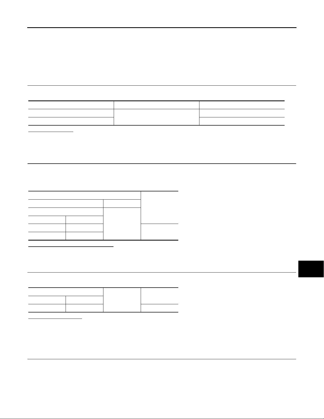
Terminal No. Signal name Fuse and fusible link No.
1
11 10
Is the fuse fusing?
YES >> Replace the blown fuse or fusible link after repairing the affected circuit if a fuse or fusible link is
blown.
NO >> GO TO 2.
Battery power supply
2.CHECK POWER SUPPLY CIRCUIT
1. Turn ignition switch OFF.
2. Disconnect BCM connectors.
3. Check voltage between BCM harness connector and ground.
K
A
B
C
D
E
F
G
H
Terminals
(+) (−)
BCM
Connector Terminal
M118 1
M119 11
Is the measurement value normal?
YES >> GO TO 3.
NO >> Repair harness or connector.
Ground
Voltage
(Approx.)
Battery voltage
3.CHECK GROUND CIRCUIT
Check continuity between BCM harness connector and ground.
BCM
Connector Terminal
M119 13 Existed
Does continuity exist?
YES >> INSPECTION END
NO >> Repair harness or connector.
Ground
BCM : Special Repair Requirement INFOID:0000000000962581
Continuity
I
J
K
INL
M
N
O
1.REQUIRED WORK WHEN REPLACING BCM
Initialize IVIS by CONSULT-III. For the details of initialization refer to CONSULT-III operation manual NATSIVIS/NVIS.
>> Work end.
P
INL-17
Page 18
INTERIOR ROOM LAMP POWER SUPPLY CIRCUIT
2007 G35 Sedan
Revision: October 2006
< COMPONENT DIAGNOSIS >
INTERIOR ROOM LAMP POWER SUPPLY CIRCUIT
Description INFOID:0000000000962582
Provides the interior room lamp power supply. Also cuts the power supply when the interior room lamp battery
saver activating.
Component Function Check INFOID:0000000000962583
1.CHECK INTERIOR ROOM LAMP POWER SUPPLY FUNCTION
CONSULT-III ACTIVE TEST
1. Turn ignition switch ON.
2. Turn each interior room lamp ON.
- Map lamp
- Personal lamp
- Step lamp
- Vanity mirror lamp
- Trunk room lamp
3. Select "BATTERY SAVER" of BCM (BATTERY SAVER) active test item.
4. With operating the test items, check that each interior room lamp turns ON/OFF.
OFF : Interior room lamp OFF
ON : Interior room lamp ON
Does the interior room lamp turn ON/OFF?
YES >> Interior room lamp power supply circuit is normal.
NO >> Refer to INL-18, "
Diagnosis Procedure".
Diagnosis Procedure INFOID:0000000000962584
1.CHECK INTERIOR ROOM LAMP POWER SUPPLY OUTPUT
CONSULT-III ACTIVE TEST
1. Turn ignition switch ON.
2. Select “BATTERY SAVER” of BCM (BATTERY SAVER) active test item.
3. With operating the test item, check voltage between BCM harness connector and ground.
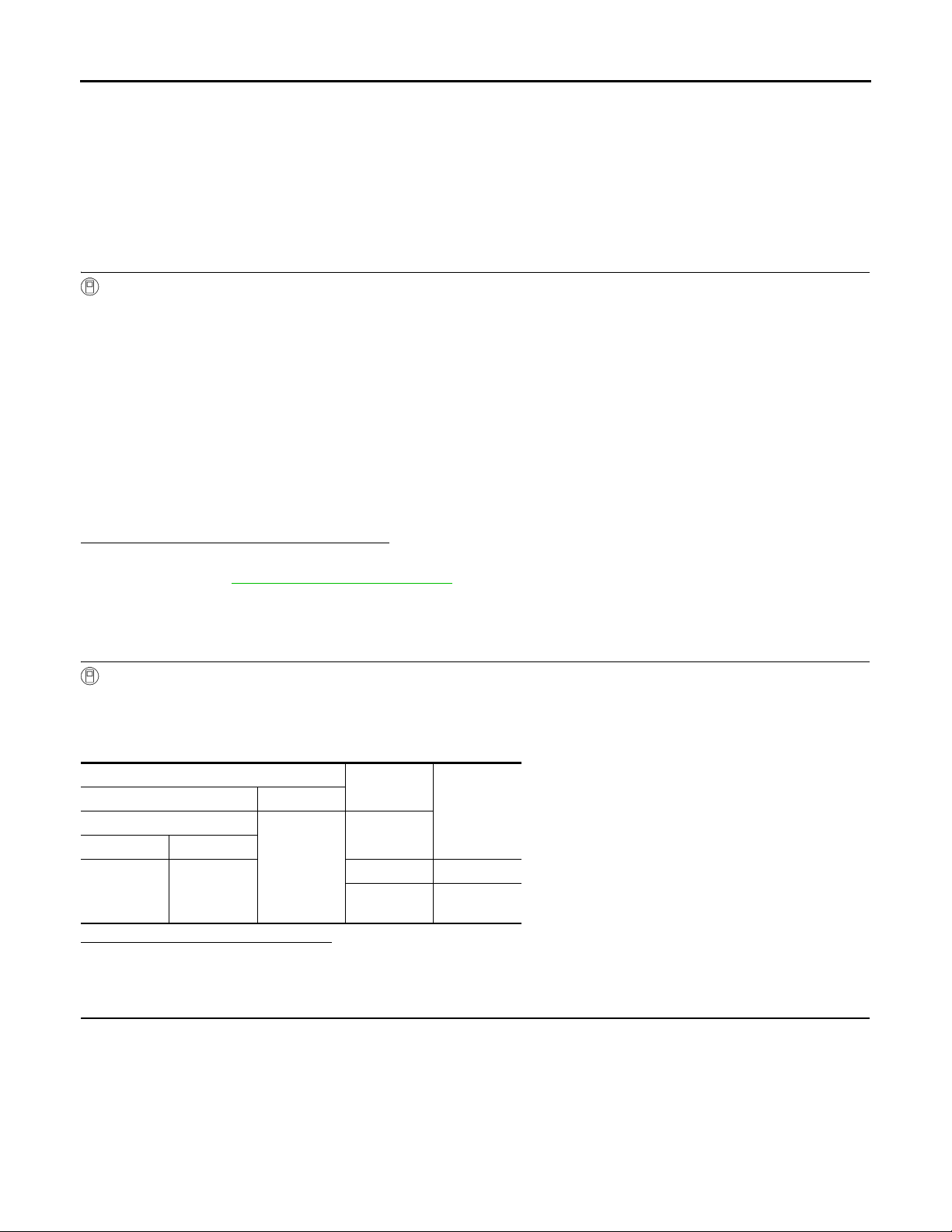
Terminals
(+) (-)
BCM
Connector Terminal
Ground
M119 4
Is the measurement value normal?
YES >> GO TO 2.
NO >> Replace BCM.
Test item
BATTERY
SAVER
OFF 0 V
ON
Voltage (Ap-
prox.)
Battery volt-
age
2.CHECK INTERIOR ROOM LAMP POWER SUPPLY OPEN CIRCUIT
1. Turn ignition switch OFF.
2. Disconnect the following connectors.
- Map lamp
- Personal lamp
- Vanity mirror lamp (LH)
- Vanity mirror lamp (RH)
- Trunk room lamp
- Step lamp (driver side)
- Step lamp (passenger side)
INL-18
Page 19
INTERIOR ROOM LAMP POWER SUPPLY CIRCUIT
2007 G35 Sedan
Revision: October 2006
< COMPONENT DIAGNOSIS >
3. Check continuity between BCM harness connector and each interior room lamp harness connector.
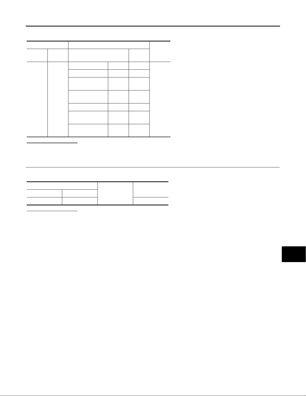
BCM Each interior room lamp
Connec-
tor
M119 4
Terminal Connector Terminal
Map lamp R15 1
Personal lamp R14 1
Vanity mirror lamp
(LH)
Vanity mirror lamp
(RH)
Trunk room lamp B47 1
Step lamp (driver
side)
Step lamp (pas-
senger side)
R12 2
R13 2
D12 1
D42 1
Continu-
ity
Existed
Does continuity exist?
YES >> GO TO 3.
NO >> Repair the harnesses or connectors.
3.CHECK INTERIOR ROOM LAMP POWER SUPPLY SHORT CIRCUIT
A
B
C
D
E
F
G
Check continuity between BCM harness connector and ground.
BCM
Connector Terminal
M119 4 Not existed
Ground
Continuity
Does continuity exist?
YES >> Repair the harnesses or connectors.
NO >> Check that each interior room lamp has no internal short circuit.
H
I
J
K
INL
M
N
O
P
INL-19
Page 20

INTERIOR ROOM LAMP CONTROL CIRCUIT
2007 G35 Sedan
Revision: October 2006
< COMPONENT DIAGNOSIS >
INTERIOR ROOM LAMP CONTROL CIRCUIT
Description INFOID:0000000000962585
Controls each interior room lamp (ground side) by PWM signal.
NOTE:
PWM signal control period is approximately 250 Hz (in the gradual brightening/dimming).
Component Function Check INFOID:0000000000962586
CAUTION:
Before performing the diagnosis, check that the following is normal.
• Interior room lamp power supply
• Map lamp bulb
• Personal lamp bulb
1.CHECK INTERIOR ROOM LAMP CONTROL FUNCTION
CONSULT-III ACTIVE TEST
1. Switch the map lamp switch to DOOR.
2. Turn ignition switch ON.
3. Select “INT LAMP” of BCM (INT LAMP) active test item.
4. With operating the test items, check that each interior room lamp turns ON/OFF (gradual brightening/dimming).
ON : Interior room lamp gradual
brightening
OFF : Interior room lamp gradual dim-
ming
Does the interior room lamp turns ON/OFF (gradual brightening/dimming)?
YES >> Interior room lamp control circuit is normal.
NO >> Refer to INL-20, "
Diagnosis Procedure".
Diagnosis Procedure INFOID:0000000000962587
1.CHECK INTERIOR ROOM LAMP CONTROL OUTPUT
CONSULT-III ACTIVE TEST
1. Turn ignition switch OFF.
2. Remove all the bulbs of map lamp and personal lamp.
3. Select “INT LAMP” of BCM (INT LAMP) active test item.
4. With operating the test item, check continuity between BCM harness connector and ground.
BCM
Connector Terminal INT LAMP
M119 19
Is the measurement value normal?
YES >> GO TO 2.
Fixed ON>>GO TO 3.
Fixed OFF>>Replace BCM.
Ground
Test item
ON Existed
OFF Not existed
Continuity
2.CHECK INTERIOR ROOM LAMP CONTROL OPEN CIRCUIT
1. Turn ignition switch OFF.
2. Disconnect BCM connector, map lamp connector and personal lamp connector.
3. Check continuity between BCM harness connector, map lamp harness connector, and personal lamp harness connector.
INL-20
Page 21
INTERIOR ROOM LAMP CONTROL CIRCUIT
2007 G35 Sedan
Revision: October 2006
< COMPONENT DIAGNOSIS >
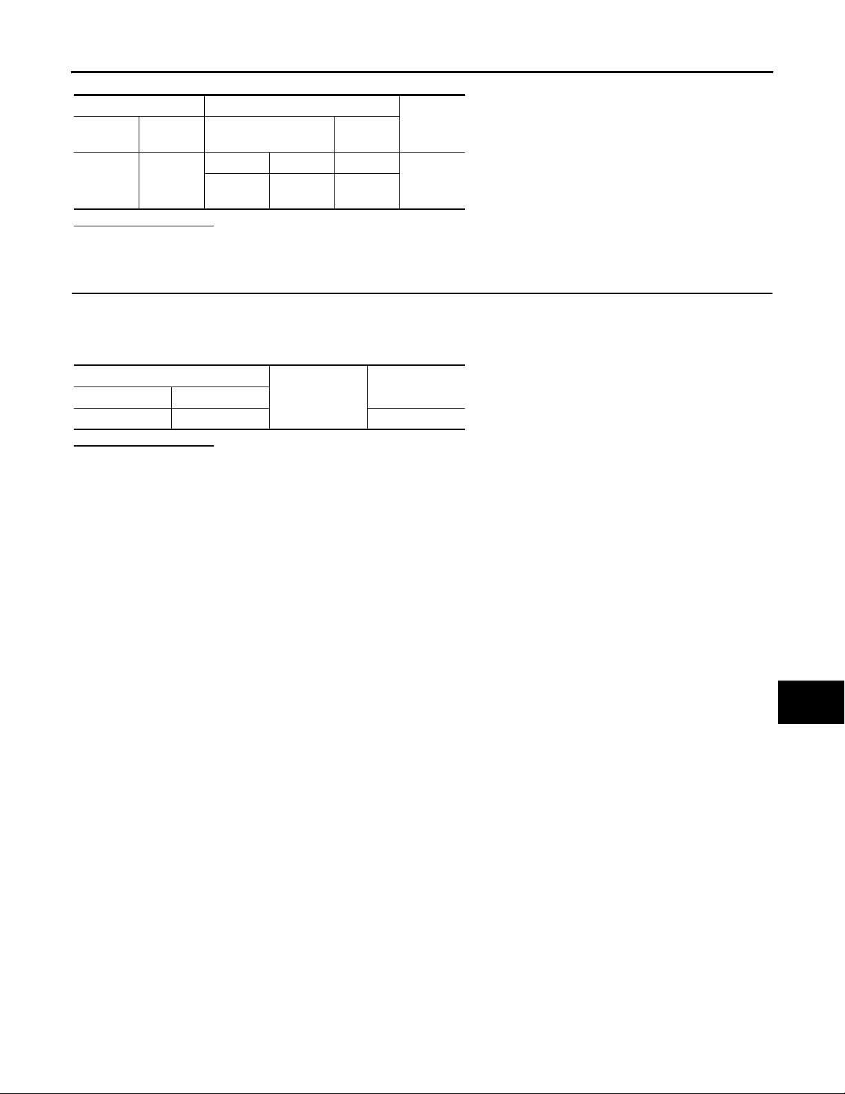
BCM Map lamp/personal lamp
Connec-
tor
M119 19
Terminal Connector Terminal
Map lamp R15 2
Personal
lamp
R14 3
Continuity
Existed
Does continuity exist?
YES >> Replace the map lamp or the personal lamp.
NO >> Repair the harnesses or connectors.
3.CHECK INTERIOR ROOM LAMP CONTROL SHORT CIRCUIT
1. Turn ignition switch OFF.
2. Disconnect BCM connector, map lamp connector and personal lamp connector.
3. Check continuity between BCM harness connector and ground.
BCM
Connector Terminal
M119 19 Not existed
Ground
Does continuity exist?
YES >> Repair the harnesses or connectors.
NO >> Replace BCM.
Continuity
A
B
C
D
E
F
G
H
J
K
INL
M
N
O
P
I
INL-21
Page 22

STEP LAMP CIRCUIT
2007 G35 Sedan
Revision: October 2006
< COMPONENT DIAGNOSIS >
STEP LAMP CIRCUIT
Description INFOID:0000000000962588
Controls the step lamp (ground side) to turn the step lamp ON and OFF.
Component Function Check INFOID:0000000000962589
CAUTION:
Before performing the diagnosis, check that the following is normal.
• Interior room lamp power supply
• Step lamp bulb
1.CHECK STEP LAMP OPRATION
CONSULT-III ACTIVE TEST
1. Turn ignition switch ON.
2. Select "STEP LAMP TEST" of BCM (INT LAMP) active test item.
3. With operating the test items, check that step lamp turns ON/OFF.
ON : Step lamp ON
OFF : Step lamp OFF
Does the step lamp turn ON/OFF?
YES >> Step lamp circuit is normal.
NO >> Refer to INL-22, "
Diagnosis Procedure".
Diagnosis Procedure INFOID:0000000000962590
1.CHECK STEP LAMP OUTPUT
CONSULT-III ACTIVE TEST
1. Turn ignition switch OFF.
2. Remove the step lamp bulbs (driver side and passenger side).
3. Turn ignition switch ON.
4. Select “STEP LAMP TEST” of BCM (INT LAMP) active test item.
5. With operating the test item, check continuity between BCM harness connector and ground.
BCM
Connector Terminal
M119 7
Is the measurement value normal?
YES >> GO TO 2.
Fixed ON>>GO TO 3.
Fixed OFF>>Replace BCM.
Ground
Test item
STEP LAMP
TEST
ON Existed
OFF Not existed
Continuity
2.CHECK STEP LAMP OPEN CIRCUIT
1. Turn ignition switch OFF.
2. Disconnect BCM connector, and step lamp connector.
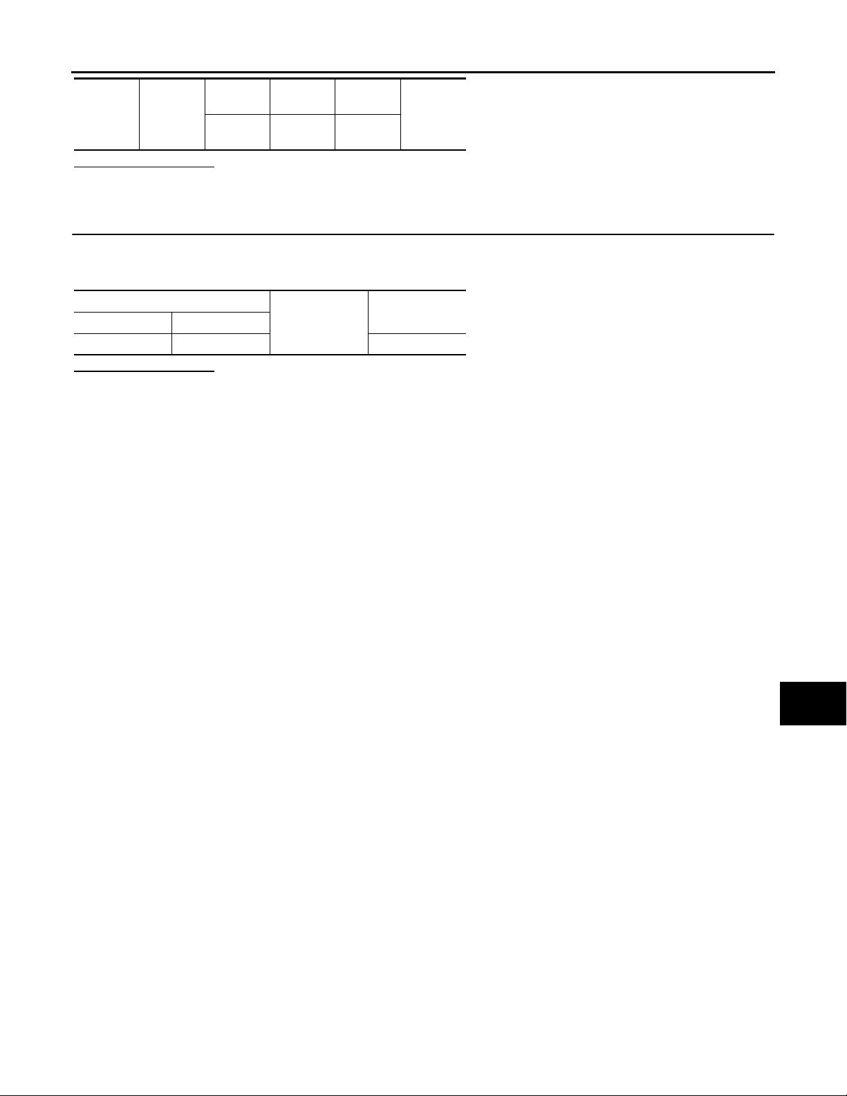
3. Check continuity between BCM harness connector and step lamp harness connector.
BCM Step lamp
Connec-
tor
Terminal Connector Terminal
Continuity
INL-22
Page 23
< COMPONENT DIAGNOSIS >
2007 G35 Sedan
Revision: October 2006
STEP LAMP CIRCUIT
M119 7
Driver
side
Passenger side
D12 2
Existed
D42 2
Does continuity exist?
YES >> Replace step lamp.
NO >> Repair harnesses or connectors.
3.CHECK STEP LAMP SHORT CIRCUIT
1. Turn ignition switch OFF.
2. Check continuity between BCM harness connector and ground.
BCM
Connector Terminal
M119 7 Not existed
Ground
Does continuity exist?
YES >> Repair the harnesses or connectors.
NO >> Replace BCM.
Continuity
A
B
C
D
E
F
G
H
J
K
INL
M
N
O
P
I
INL-23
Page 24

TRUNK ROOM LAMP CIRCUIT
2007 G35 Sedan
Revision: October 2006
< COMPONENT DIAGNOSIS >
TRUNK ROOM LAMP CIRCUIT
Description INFOID:0000000000962591
Controls the trunk room lamp (ground side) to turn the trunk room lamp ON and OFF.
Component Function Check INFOID:0000000000962592
CAUTION:
Before performing the diagnosis, check that the following is normal.
• Interior room lamp power supply
• Trunk room lamp bulb
1.CHECK TRUNK ROOM LAMP OPRATION
CONSULT-III ACTIVE TEST
1. Turn ignition switch ON.
2. Select “LUGGAGE LAMP TEST” of BCM (INT LAMP) active test item.
3. With operating the test items, check that trunk room lamp turns ON/OFF.
ON : Trun k room lamp ON
OFF : Trunk room lamp OFF
Does the trunk room lamp turn ON/OFF?
YES >> Trunk room lamp circuit is normal.
NO >> Refer to INL-22, "
Diagnosis Procedure".
Diagnosis Procedure INFOID:0000000000962593
1.CHECK TRUNK ROOM LAMP OUTPUT
CONSULT-III ACTIVE TEST
1. Turn ignition switch OFF.
2. Remove trunk room lamp bulb.
3. Turn ignition switch ON.
4. Select “LUGGAGE LAMP TEST” of BCM (INT LAMP) active test item.
5. With operating the test item, check continuity between BCM harness connector and ground.
BCM
Connector Terminal
M120 30
Is the measurement value normal?
YES >> GO TO 2.
Fixed ON>>GO TO 3.
Fixed OFF>>Replace BCM.
Ground
Test item
LUGGAGE
LAMP TEST
ON Existed
OFF N ot ex isted
Continuity
2.CHECK TRUNK ROOM LAMP OPEN CIRCUIT
1. Turn ignition switch OFF.
2. Disconnect BCM connector and trunk room lamp connector.
3. Check continuity between BCM harness connector and trunk room lamp harness connector.
Connector Terminal Connector Terminal
M120 30 B47 2 Existed
Does continuity exist?
YES >> Replace trunk room lamp.
BCM Trunk room lamp
Continuity
INL-24
Page 25

TRUNK ROOM LAMP CIRCUIT
2007 G35 Sedan
Revision: October 2006
< COMPONENT DIAGNOSIS >
NO >> Repair harnesses or connectors.
3.CHECK TRUNK ROOM LAMP SHORT CIRCUIT
1. Turn ignition switch OFF.
2. Disconnect BCM connector and trunk room lamp connector.
3. Check continuity between BCM harness connector and ground.
A
B
BCM
Connector Terminal
M120 30 Not existed
Ground
Does continuity exist?
YES >> Repair harnesses or connectors.
NO >> Replace BCM.
Continuity
C
D
E
F
G
H
I
J
K
INL
M
N
O
P
INL-25
Page 26
PUSH-BUTTON IGNITION SWITCH ILLUMINATION CIRCUIT
2007 G35 Sedan
Revision: October 2006
< COMPONENT DIAGNOSIS >
PUSH-BUTTON IGNITION SWITCH ILLUMINATION CIRCUIT
Description INFOID:0000000000962594
Provides the power supply and the ground to control the push-button ignition switch illumination.
Component Function Check INFOID:0000000000962595
1.CHECK PUSH-BUTTON IGNITION SWITCH ILLUMINATION OPERATION
CONSULT-III ACTIVE TEST
1. Turn the ignition switch ON.
2. Select “ENGINE SW ILLUMI” of BCM (INTELLGENT KEY) active test item.
3. With operating the test items, check that the push-button ignition switch illumination turns ON/OFF
ON : Push-button ignition switch illumination ON
OFF : Push-button ignition switch illumination OFF
Does the push-button ignition switch illumination turn ON/OFF?
YES >> Push-button ignition switch illumination circuit is normal.
NO >> Refer to INL-26, "
Diagnosis Procedure INFOID:0000000000962596
Diagnosis Procedure".
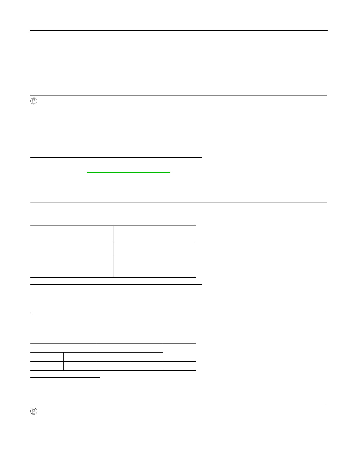
1.CHECK ILLUMINATION CONTROL SWITCHING OPERATION
1. Turn the ignition switch ON.
2. With operating the lighting switch, check that the push-button ignition switch illumination turns ON/OFF
Condition
• Ignition switch ON
• Lighting switch 1ST
• Ignition switch OFF
• Lighting switch OFF
• Driver door LOCK
Does the push-button ignition switch illumination turn ON/OFF?
YES >> GO TO 2.
NO >> GO TO 3.
Push-button ignition switch illumina-
tion
ON
OFF
2.CHECK PUSH-BUTTON IGNITION SWITCH ILLUMINATION GROUND CIRCUIT
1. Turn the ignition switch OFF.
2. Disconnect BCM connector and the push-button ignition switch connector.
3. Check continuity between BCM harness connector and the push-button ignition switch harness connector.
BCM Push-button ignition switch
Connector Terminal Connector Terminal
M119 14 M50 2 Existed
Does the continuity exist?
YES >> Replace BCM.
NO >> Repair the harness or the connector.
Continuity
3.CHECK PUSH-BUTTON IGNITION SWITCH ILLUMINATION POWER SUPPLY OUTPUT
CONSULT-III ACTIVE TEST
1. Turn the ignition switch ON.
2. Select “ENGINE SW ILLUMI” of BCM (INTELLGENT KEY) active test item.
3. With operating the test item, check voltage between BCM harness connector and ground.
INL-26
Page 27
PUSH-BUTTON IGNITION SWITCH ILLUMINATION CIRCUIT
2007 G35 Sedan
Revision: October 2006
< COMPONENT DIAGNOSIS >
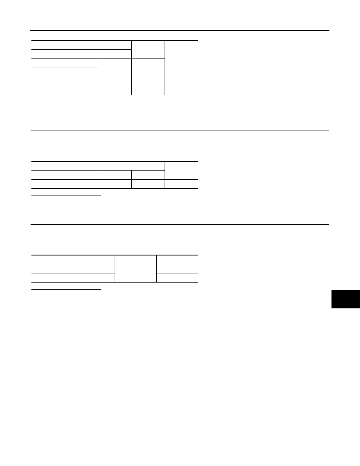
Terminals
(+) (-)
BCM
Connector Terminal
M123 133
Ground
Test item
ENGINE SW
ILLUMI
ON 5 V
OFF 0 V
Voltage (Ap-
prox.)
Is the measurement value normal?
YES >> GO TO 4.
NO >> GO TO 5.
4.CHECK PUSH-BUTTON IGNITION SWITCH ILLUMINATION POWER SUPPLY OPEN CIRCUIT
1. Turn the ignition switch OFF.
2. Disconnect BCM connector and the push-button ignition switch connector.
3. Check continuity between BCM harness connector and the push-button ignition switch harness connector.
BCM Push-button ignition switch
Connector Terminal Connector Terminal
M123 133 M50 3 Existed
Continuity
Does the continuity exist?
YES >> Replace push-button ignition switch.
NO >> Repair the harness or the connector.
5.CHECK PUSH-BUTTON IGNITION SWITCH ILLUMINATION POWER SUPPLY SHORT CIRCUIT
A
B
C
D
E
F
G
H
1. Turn the ignition switch OFF.
2. Disconnect BCM connector and the push-button ignition switch connector.
3. Check continuity between BCM harness connector and the push-button ignition switch harness connector.
BCM
Connector Terminal
M123 133 Not existed
Ground
Continuity
Does the continuity exist?
YES >> Repair the harness or the connector.
NO >> Replace BCM.
I
J
K
INL
M
N
O
P
INL-27
Page 28
INTERIOR ROOM LAMP CONTROL SYSTEM
B
2007 G35 Sedan
Revision: October 2006
< COMPONENT DIAGNOSIS >
INTERIOR ROOM LAMP CONTROL SYSTEM
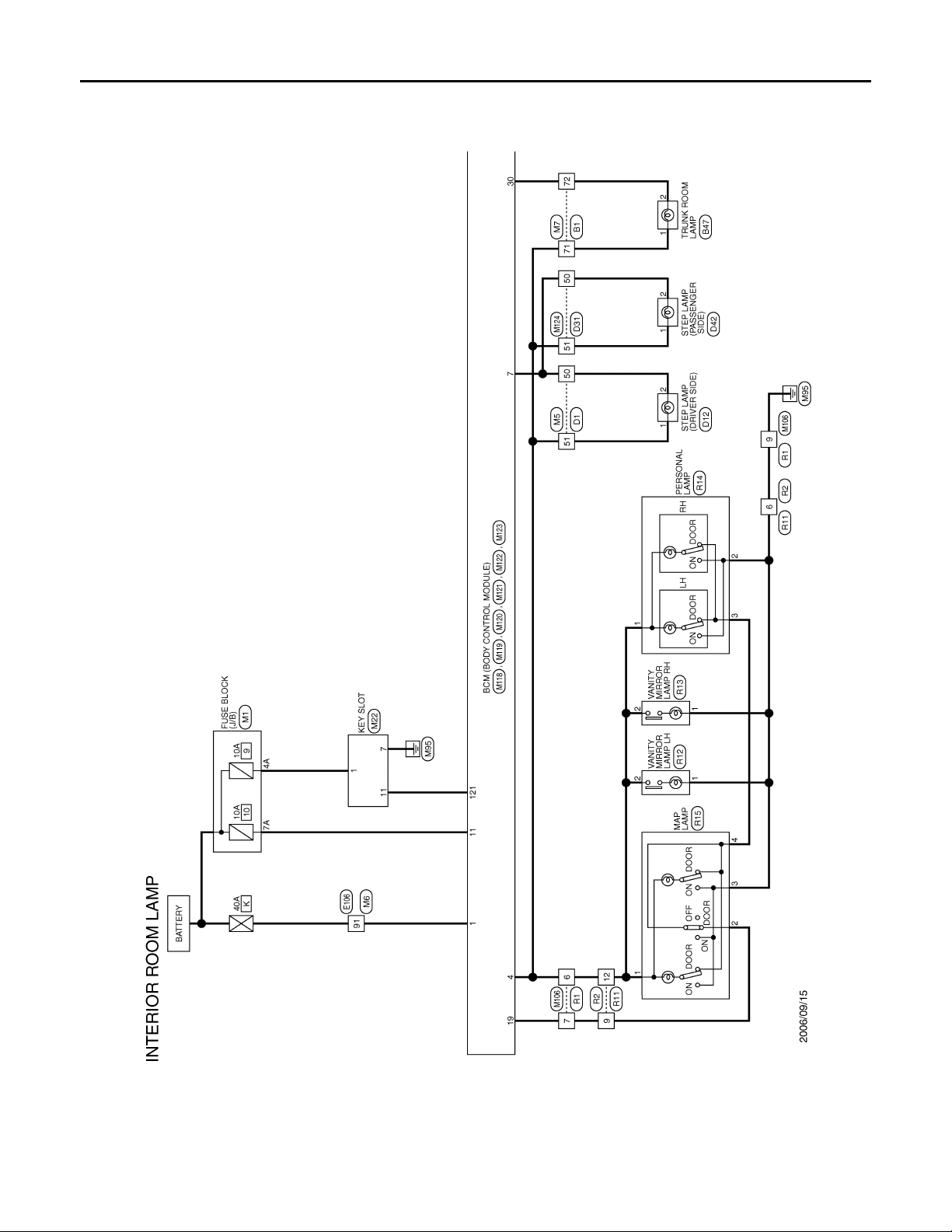
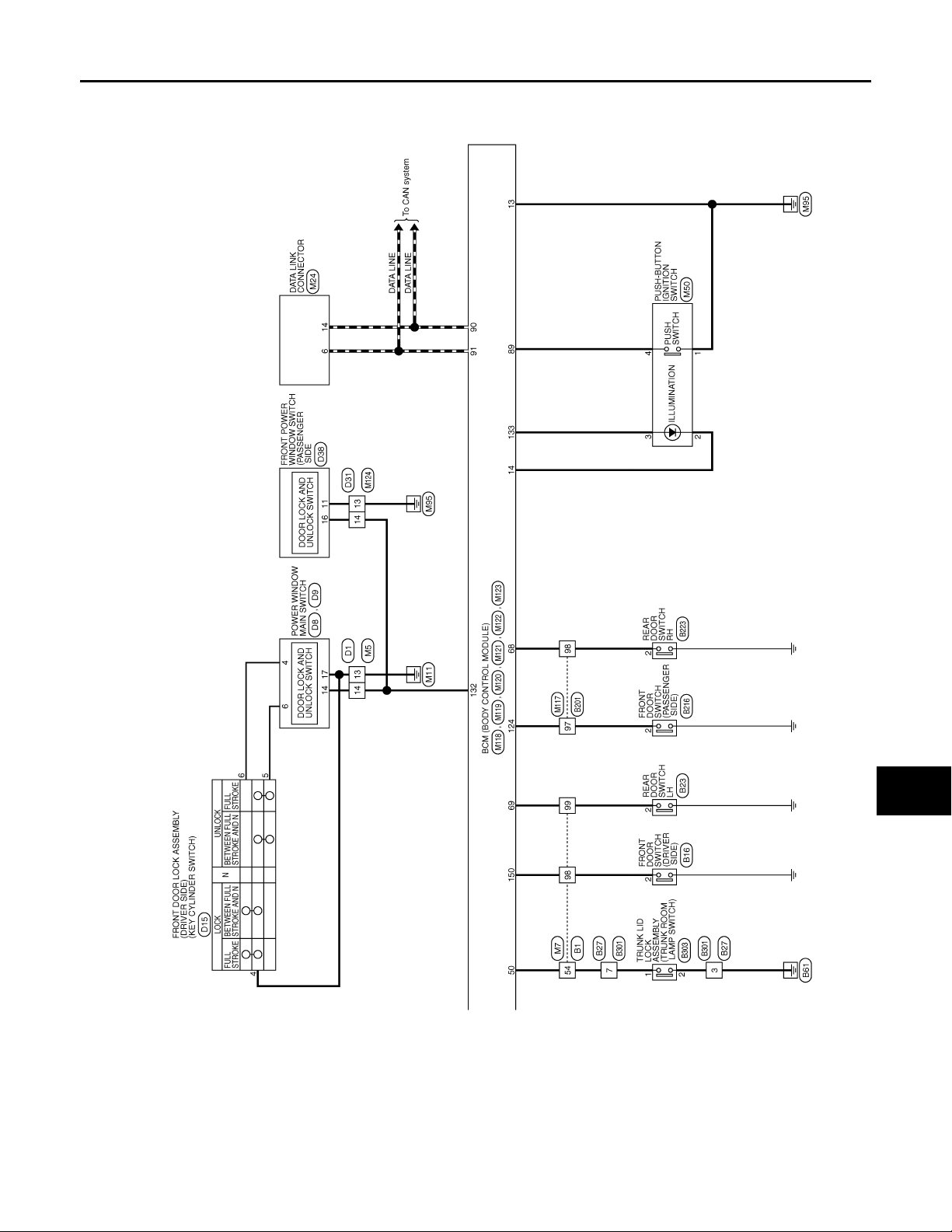
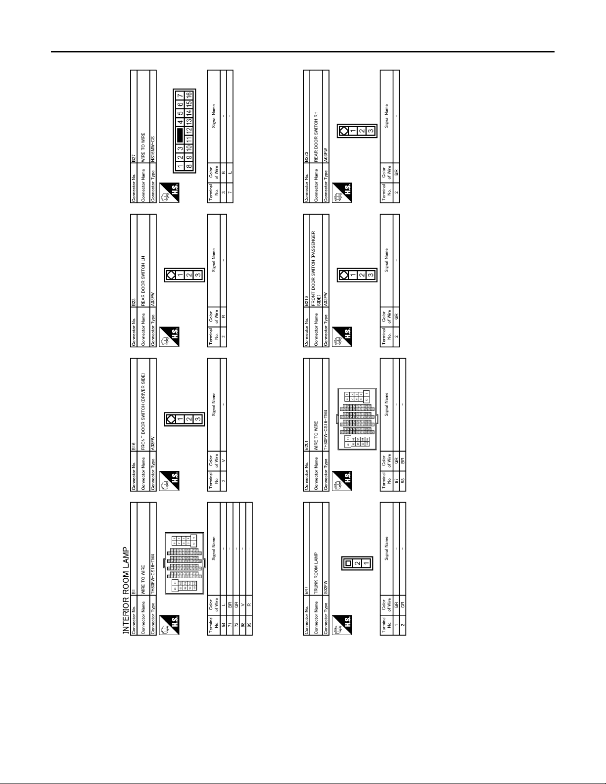
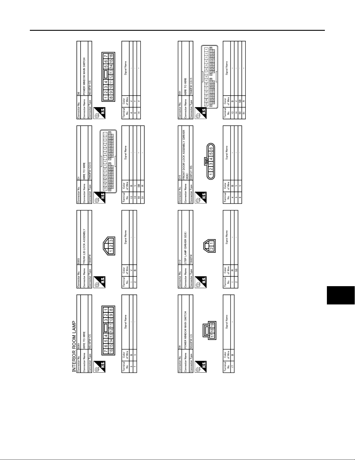
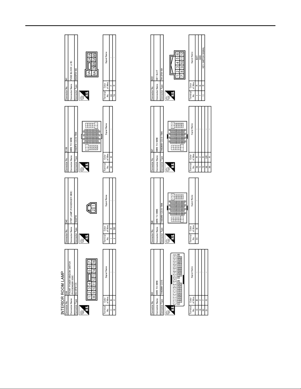
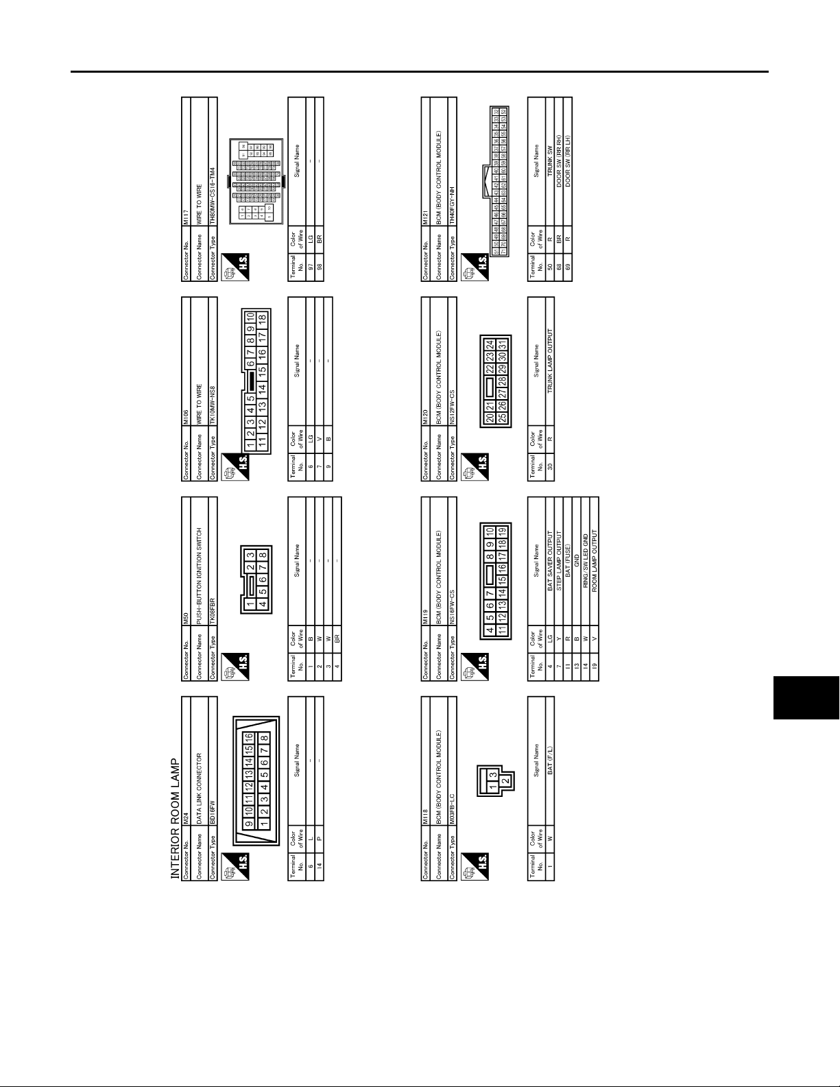
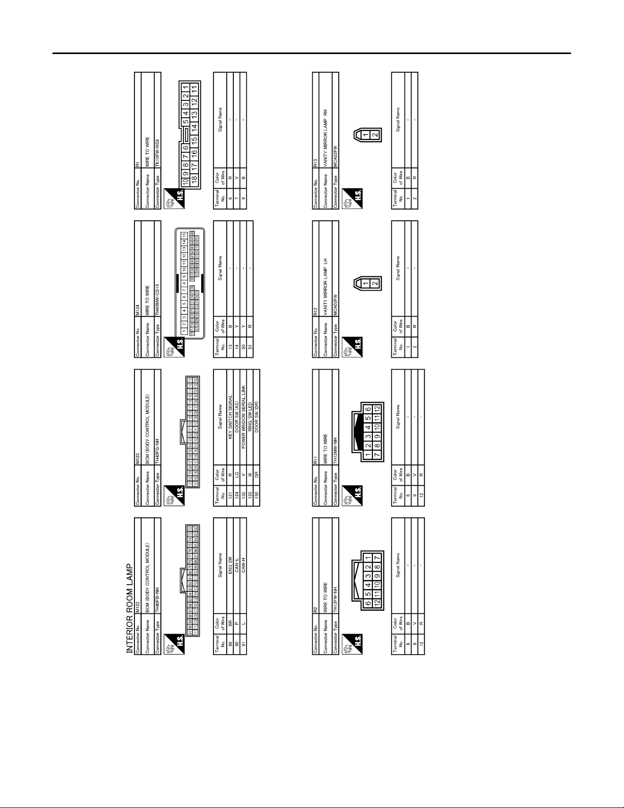
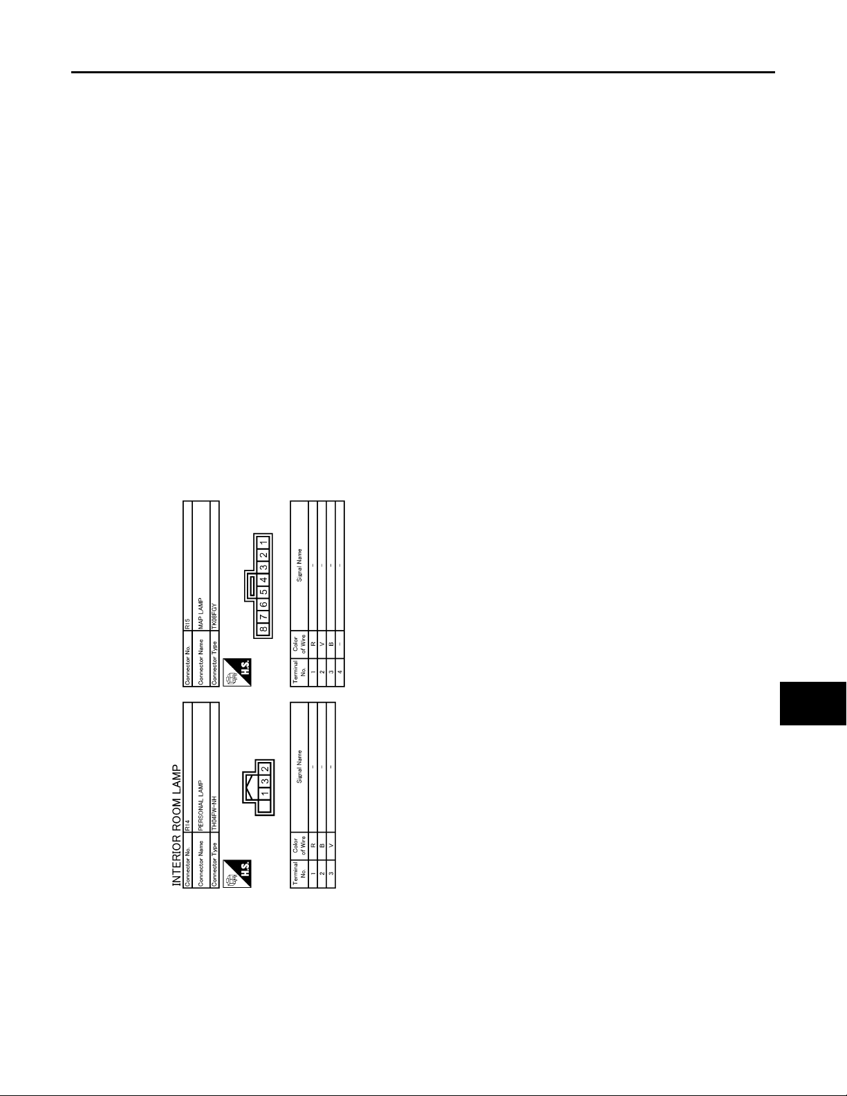
Wiring Diagram —INTERIOR ROOM LAMP — INFOID:0000000000962597
JCLWA0047G
INL-28
Page 29
INTERIOR ROOM LAMP CONTROL SYSTEM
B
2007 G35 Sedan
Revision: October 2006
< COMPONENT DIAGNOSIS >
A
B
C
D
E
F
G
H
J
K
INL
M
N
O
I
JCLWA0048G
P
INL-29
Page 30
INTERIOR ROOM LAMP CONTROL SYSTEM
B
2007 G35 Sedan
Revision: October 2006
< COMPONENT DIAGNOSIS >
JCLWA0049G
INL-30
Page 31
INTERIOR ROOM LAMP CONTROL SYSTEM
B
2007 G35 Sedan
Revision: October 2006
< COMPONENT DIAGNOSIS >
A
B
C
D
E
F
G
H
J
K
INL
M
N
O
I
JCLWA0050G
P
INL-31
Page 32
INTERIOR ROOM LAMP CONTROL SYSTEM
B
2007 G35 Sedan
Revision: October 2006
< COMPONENT DIAGNOSIS >
JCLWA0051G
INL-32
Page 33
INTERIOR ROOM LAMP CONTROL SYSTEM
B
2007 G35 Sedan
Revision: October 2006
< COMPONENT DIAGNOSIS >
A
B
C
D
E
F
G
H
J
K
INL
M
N
O
I
JCLWA0052G
P
INL-33
Page 34
INTERIOR ROOM LAMP CONTROL SYSTEM
B
2007 G35 Sedan
Revision: October 2006
< COMPONENT DIAGNOSIS >
JCLWA0053G
INL-34
Page 35
INTERIOR ROOM LAMP CONTROL SYSTEM
B
2007 G35 Sedan
Revision: October 2006
< COMPONENT DIAGNOSIS >
A
B
C
D
E
F
G
H
J
K
INL
M
N
O
I
JCLWA0054G
P
INL-35
Page 36
ILLUMINATION
B
2007 G35 Sedan
Revision: October 2006
< COMPONENT DIAGNOSIS >
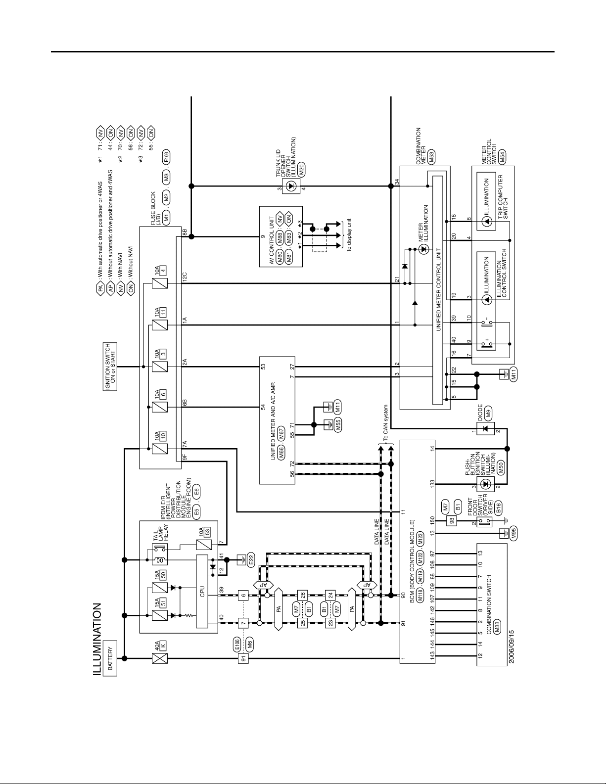
ILLUMINATION
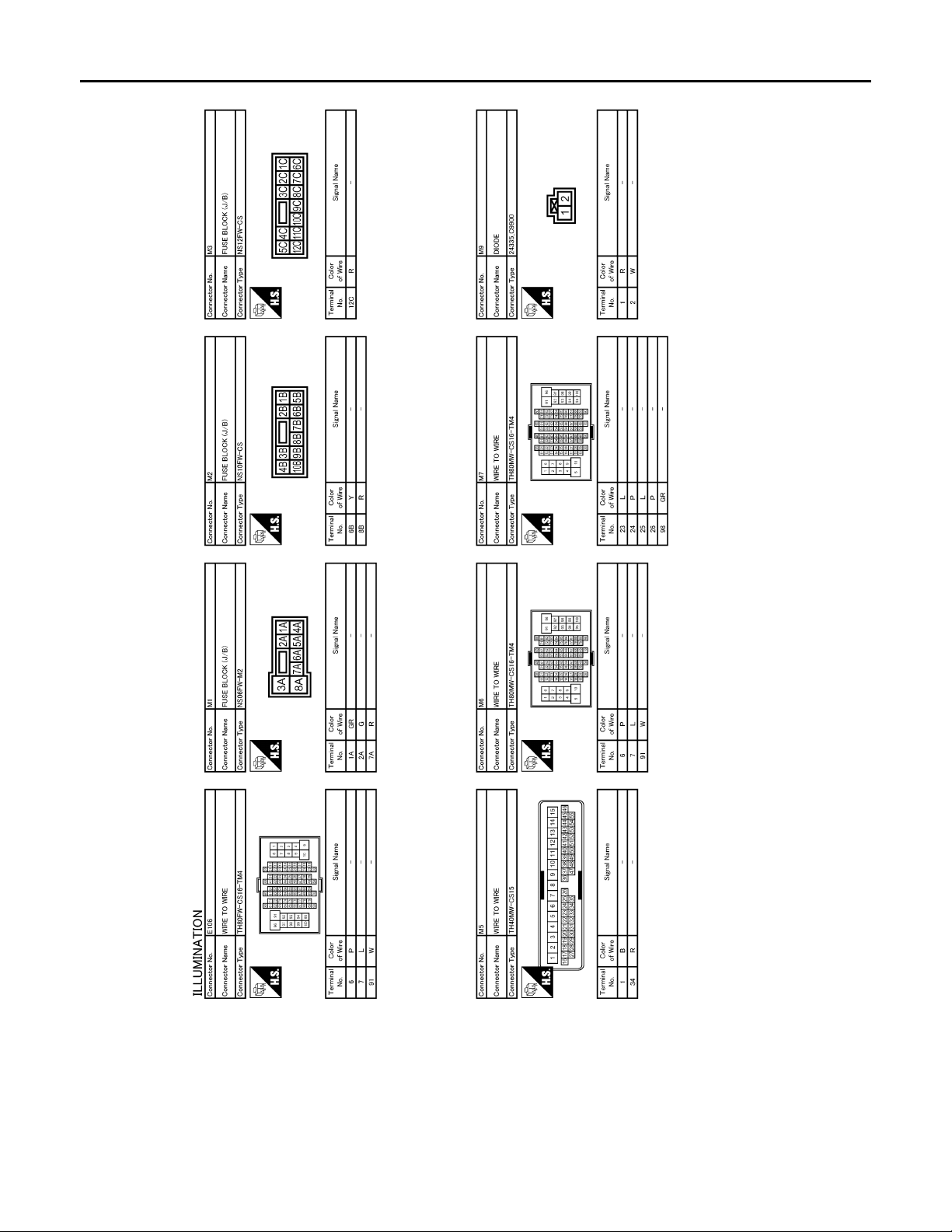
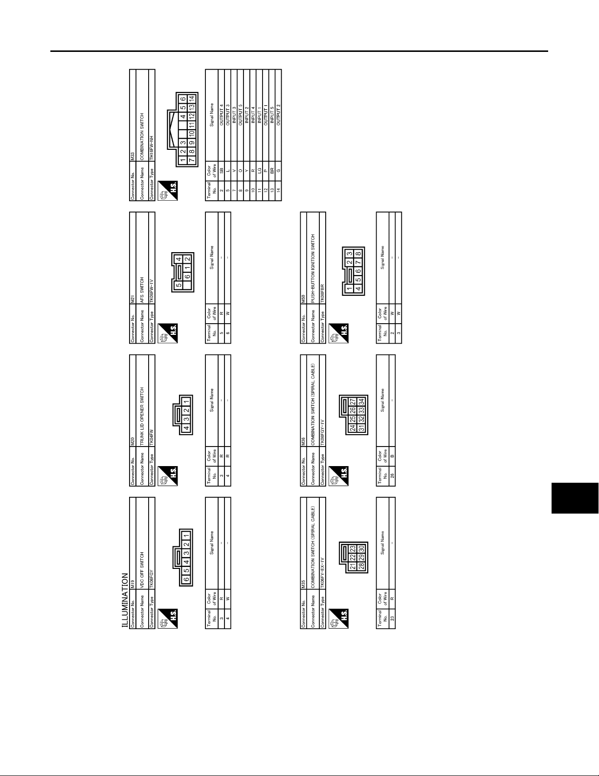
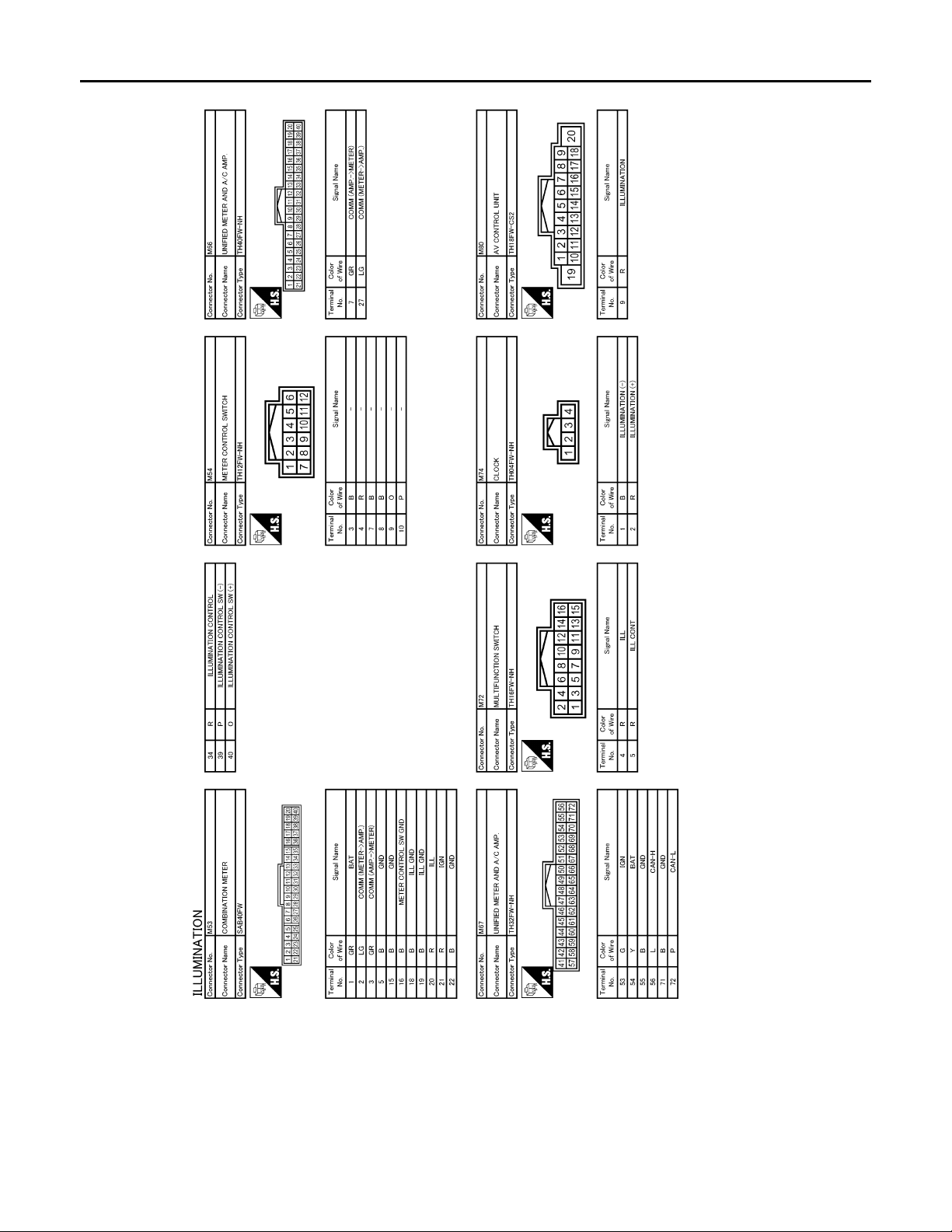
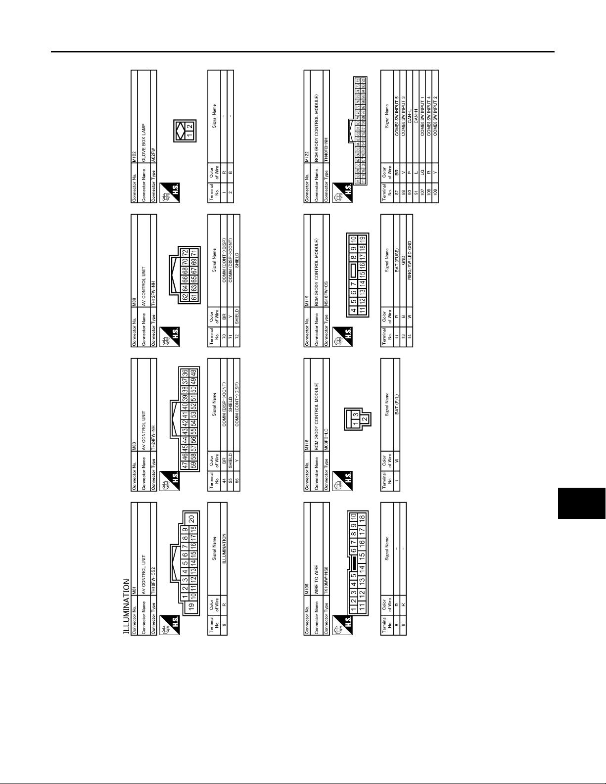
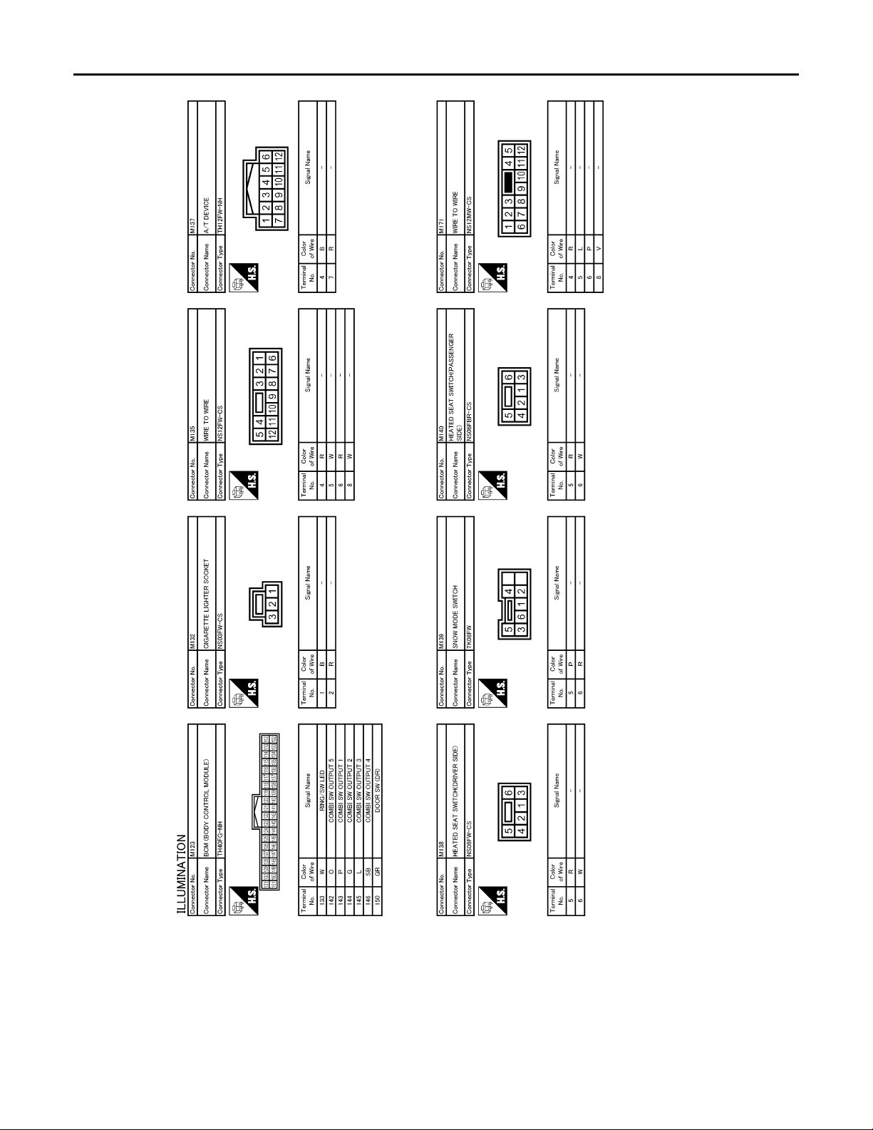
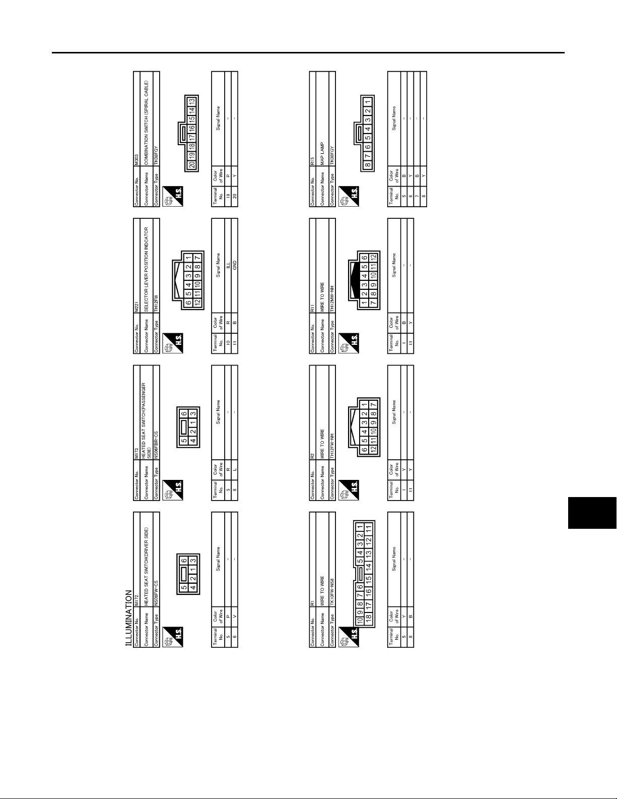
Wiring Diagram —ILLUMINATION— INFOID:0000000000962598
JCLWA0055G
INL-36
Page 37
< COMPONENT DIAGNOSIS >
B
2007 G35 Sedan
Revision: October 2006
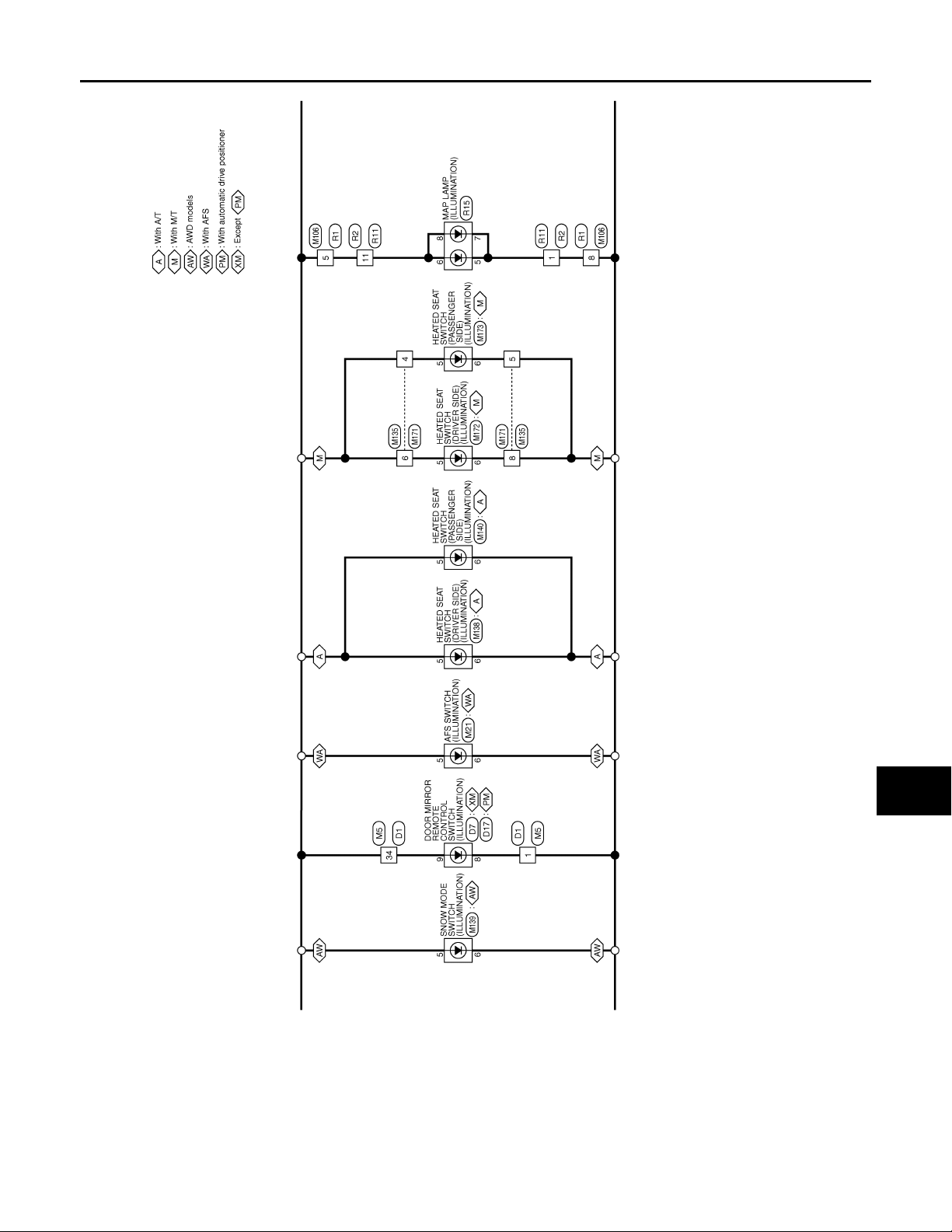
ILLUMINATION
A
B
C
D
E
F
G
H
J
K
INL
M
N
O
I
JCLWA0056G
P
INL-37
Page 38
< COMPONENT DIAGNOSIS >
B
2007 G35 Sedan
Revision: October 2006
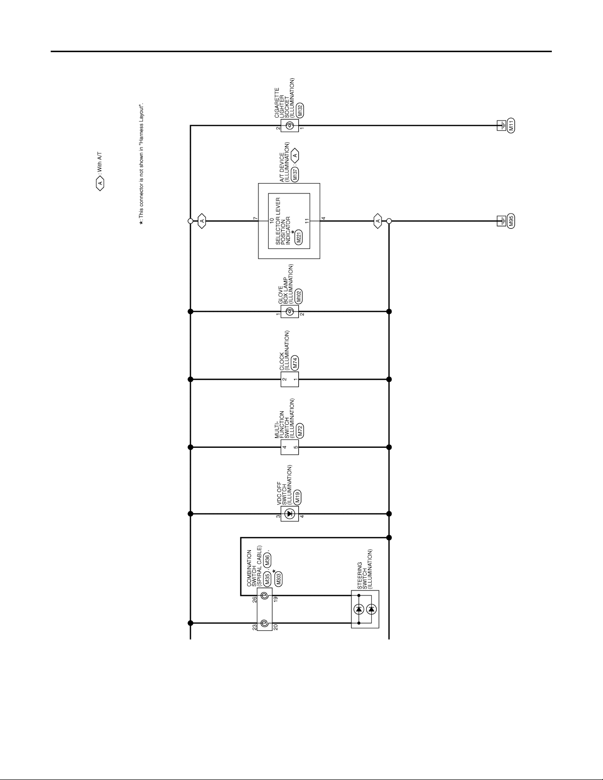
ILLUMINATION
JCLWA0057G
INL-38
Page 39
< COMPONENT DIAGNOSIS >
B
2007 G35 Sedan
Revision: October 2006
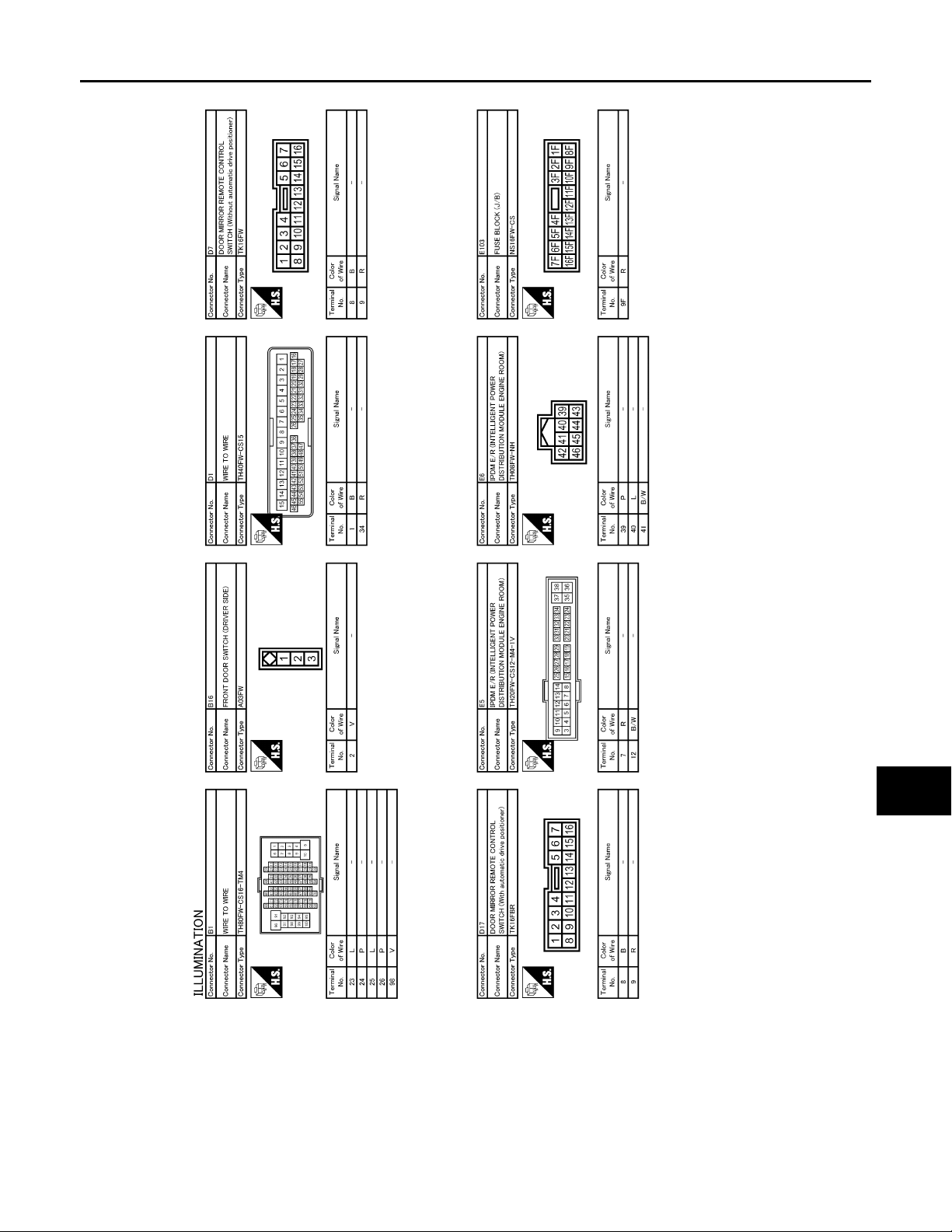
ILLUMINATION
A
B
C
D
E
F
G
H
J
K
INL
M
N
O
I
JCLWA0058G
P
INL-39
Page 40
< COMPONENT DIAGNOSIS >
B
2007 G35 Sedan
Revision: October 2006
ILLUMINATION
JCLWA0059G
INL-40
Page 41
< COMPONENT DIAGNOSIS >
B
2007 G35 Sedan
Revision: October 2006
ILLUMINATION
A
B
C
D
E
F
G
H
J
K
INL
M
N
O
I
JCLWA0060G
P
INL-41
Page 42
< COMPONENT DIAGNOSIS >
B
2007 G35 Sedan
Revision: October 2006
ILLUMINATION
JCLWA0061G
INL-42
Page 43
< COMPONENT DIAGNOSIS >
B
2007 G35 Sedan
Revision: October 2006
ILLUMINATION
A
B
C
D
E
F
G
H
J
K
INL
M
N
O
I
JCLWA0062G
P
INL-43
Page 44
< COMPONENT DIAGNOSIS >
B
2007 G35 Sedan
Revision: October 2006
ILLUMINATION
JCLWA0063G
INL-44
Page 45
< COMPONENT DIAGNOSIS >
B
2007 G35 Sedan
Revision: October 2006
ILLUMINATION
A
B
C
D
E
F
G
H
J
K
INL
M
N
O
I
JCLWA0064G
P
INL-45
Page 46

BCM (BODY CONTROL MODULE)
2007 G35 Sedan
Revision: October 2006
< ECU DIAGNOSIS >
ECU DIAGNOSIS
BCM (BODY CONTROL MODULE)
Reference Value INFOID:0000000000962599
VALUES ON THE DIAGNOSIS TOOL
Monitor Item Condition Value/Status
FR WIPER HI
FR WIPER LOW
FR WASHER SW
FR WIPER INT
FR WIPER STOP
INT VOLUME Wiper intermittent dial is in a dial position 1 - 7 Wiper intermittent dial position
TURN SIGNAL R
TURN SIGNAL L
TAIL LAMP SW
HI BEAM SW
HEAD LAMP SW 1
HEAD LAMP SW 2
PASSING SW
AUTO LIGHT SW
FR FOG SW
RR FOG SW
DOOR SW-DR
DOOR SW-AS
DOOR SW-RR
Other than front wiper switch HI OFF
Front wiper switch HI ON
Other than front wiper switch LO OFF
Front wiper switch LO ON
Front washer switch OFF OFF
Front washer switch ON ON
Other than front wiper switch INT OFF
Front wiper switch INT ON
Front wiper is not in STOP position OFF
Front wiper is in STOP position ON
Other than turn signal switch RH OFF
Turn signal switch RH ON
Other than turn signal switch LH OFF
Turn signal switch LH ON
Other than lighting switch 1ST and 2ND OFF
Lighting switch 1ST or 2ND ON
Other than lighting switch HI OFF
Lighting switch HI ON
Other than lighting switch 2ND OFF
Lighting switch 2ND ON
Other than lighting switch 2ND OFF
Lighting switch 2ND ON
Other than lighting switch PASS OFF
Lighting switch PASS ON
Other than lighting switch AUTO OFF
Lighting switch AUTO ON
Front fog lamp switch OFF OFF
Front fog lamp switch ON ON
NOTE:
The item is indicated, but not monitored.
Driver door closed OFF
Driver door opened ON
Passenger door closed OFF
Passenger door opened ON
Rear RH door closed OFF
Rear RH door opened ON
OFF
INL-46
Page 47

< ECU DIAGNOSIS >
2007 G35 Sedan
Revision: October 2006
BCM (BODY CONTROL MODULE)
Monitor Item Condit ion Value/Status
DOOR SW-RL
DOOR SW-BK
CDL LOCK SW
CDL UNLOCK SW
KEY CYL LK-SW
KEY CYL UN-SW
KEY CYL SW-TR
HAZARD SW
REAR DEF SW
H/L WASH SW
TR CANCEL SW
TR/BD OPEN SW
TRNK/HAT MNTR
RKE-LOCK
RKE-UNLOCK
RKE-TR/BD
RKE-PANIC
RKE-P/W OPEN
RKE-MODE CHG
OPTICAL SENSOR
REQ SW-DR
REQ SW-AS
Rear LH door closed OFF
Rear LH door opened ON
NOTE:
The item is indicated, but not monitored.
Other than power door lock switch LOCK OFF
Power door lock switch LOCK ON
Other than power door lock switch UNLOCK OFF
Power door lock switch UNLOCK ON
Other than driver door key cylinder LOCK position OFF
Driver door key cylinder LOCK position ON
Other than driver door key cylinder UNLOCK position OFF
Driver door key cylinder UNLOCK position ON
NOTE:
The item is indicated, but not monitored.
Hazard switch is not pressed OFF
Hazard switch is pressed ON
NOTE:
The item is indicated, but not monitored.
NOTE:
The item is indicated, but not monitored.
Trunk lid opener cancel switch OFF OFF
Trunk lid opener cancel switch ON ON
Trunk lid opener switch OFF OFF
While the trunk lid opener switch is turned ON ON
Trunk lid closed OFF
Trunk lid opened ON
LOCK button of Intelligent Key is not pressed OFF
LOCK button of Intelligent Key is pressed ON
UNLOCK button of Intelligent Key is not pressed OFF
UNLOCK button of Intelligent Key is pressed ON
TRUNK OPEN button of Intelligent Key is not pressed OFF
TRUNK OPEN button of Intelligent Key is pressed ON
PANIC button of Intelligent Key is not pressed OFF
PANIC button of Intelligent Key is pressed ON
UNLOCK button of Intelligent Key is not pressed OFF
UNLOCK button of Intelligent Key is pressed and held ON
LOCK/UNLOCK button of Intelligent Key is not pressed and held si-
multaneously
LOCK/UNLOCK button of Intelligent Key i s pressed and held simul-
taneously
Outside of the vehicle bri ght Close to 5 V
Outside of the vehicle dark Close to 0 V
Driver door request switch is not pressed OFF
Driver door request switch is pre ssed ON
Passenger door request switch is not press ed OFF
Passenger door request switch is pressed ON
OFF
OFF
OFF
OFF
OFF
ON
A
B
C
D
E
F
G
H
I
J
K
INL
M
N
O
P
INL-47
Page 48

BCM (BODY CONTROL MODULE)
2007 G35 Sedan
Revision: October 2006
< ECU DIAGNOSIS >
Monitor Item Condition Value/Status
REQ SW-BD/TR
PUSH SW
IGN RLY2 -F/B
ACC RLY -F/B
CLUCH SW
BRAKE SW 1
DETE/CANCL SW
SFT PN/N SW
S/L -LOCK
S/L -UNLOCK
S/L RELAY-F/B
UNLK SEN-DR
PUSH SW -IPDM
IGN RLY1 -F/B
DETE SW -IPDM
SFT PN -IPDM
SFT P -MET
SFT N -MET
ENGINE STATE
S/L LOCK-IPDM
S/L UNLK-IPDM
Trunk request switch is not pressed OFF
Trunk request switch is pressed ON
Push-button ignition switch (push switch) is not pressed OFF
Push-button ignition switch (push switch) is pressed ON
Ignition switch in OFF or ACC position OFF
Ignition switch in ON position ON
Ignition switch in OFF position OFF
Ignition switch in ACC or ON position ON
The clutch pedal is not depressed OFF
The clutch pedal is depressed ON
The brake pedal is not depressed ON
The brake pedal is depressed OFF
Selector lever in P position OFF
Selector lever in any position other than P ON
Selector lever in any position other than P and N OFF
Selector lever in P or N position ON
Steering is locked OFF
Steering is unlocked ON
Steering is unlocked OFF
Steering is locked ON
Ignition switch is OFF or ACC position OFF
Ignition switch is ON posi tion ON
Driver door is unlocked OFF
Driver door is locked ON
Push-button ignition switch (push-sw itch) is not pressed OF F
Push-button ignition switch (push-switch) is pressed ON
Ignition switch is OFF or ACC position OFF
Ignition switch is ON posi tion ON
Selector lever in P position OFF
Selector lever in any position other than P ON
Selector lever in any position other than P and N OFF
Selector lever in P or N position ON
Selector lever in any position other than P OFF
Selector lever in P position ON
Selector lever in any position other than N OFF
Selector lever in N position ON
Engine stopped STOP
While the engine stalls STALL
At engine cranking CRANK
Engine running RUN
Steering is locked OFF
Steering is unlocked ON
Steering is unlocked OFF
Steering is locked ON
INL-48
Page 49

< ECU DIAGNOSIS >
2007 G35 Sedan
Revision: October 2006
BCM (BODY CONTROL MODULE)
Monitor Item Condit ion Value/Status
S/L RELAY-REQ
VEH SPEED 1 While driving Equivalent to speedometer reading
VEH SPEED 2 While driving Equivalent to speedometer reading
DOOR STAT-DR
DOOR STAT-AS
ID OK FLAG
PRMT ENG STRT
PRMT RKE STRT
KEY SW -SLOT
RKE OPE COUN1 During the operation of Intelligent Key Operation frequency of Intelligent Key
RKE OPE COUN2
AIR PRESS FL
AIR PRESS FR
AIR PRESS RR
AIR PRESS RL
ID REGST FL1
ID REGST FR1
ID REGST RR1
ID REGST RL1
WARNING LAMP
BUZZER
Ignition switch in OFF or ACC position OFF
Ignition switch in ON position ON
Driver door is locked LOCK
Wait with selective UNLOCK operation (5 seconds) READY
Driver door is unlocked UNLK
Passenger door is locked LOCK
Wait with selective UNLOCK operation (5 seconds) READY
Passenger door is unlocked UNLK
Ignition switch in ACC or ON position RESET
Ignition switch in OFF position SET
The engine start is prohibited RESET
The engine start is permitted SET
NOTE:
The item is indicated, but not monitored.
Intelligent Key is not inserted into key slot OFF
Intelligent Key is inserted into key slot ON
NOTE:
The item is indicated, but not monitored.
Ignition switch ON (Only when the signal from the transmitter is re-
ceived)
Ignition switch ON (Only when the signal from the transmitter is re-
ceived)
Ignition switch ON (Only when the signal from the transmitter is re-
ceived)
Ignition switch ON (Only when the signal from the transmitter is re-
ceived)
ID of front LH tire transmitter is registered DONE
ID of front LH tire transmitter is not registered YET
ID of front RH tire transmitter is registered DONE
ID of front RH tire transmitter is not registered YET
ID of rear RH tire transmitter is registered DONE
ID of rear RH tire transmitter is not registered YET
ID of rear LH tire transmitter is registered DONE
ID of rear LH tire transmitter is not registered YET
Tire pressure indicator OFF OFF
Tire pressure indicator ON ON
Tire pressure warning alarm is not sounding OFF
Tire pressure warning alarm is sounding ON
RESET
Air pressure of front LH tire
Air pressure of front RH tire
Air pressure of rear RH tire
Air pressure of rear LH tire
—
A
B
C
D
E
F
G
H
I
J
K
INL
M
N
O
P
INL-49
Page 50
< ECU DIAGNOSIS >
2007 G35 Sedan
Revision: October 2006
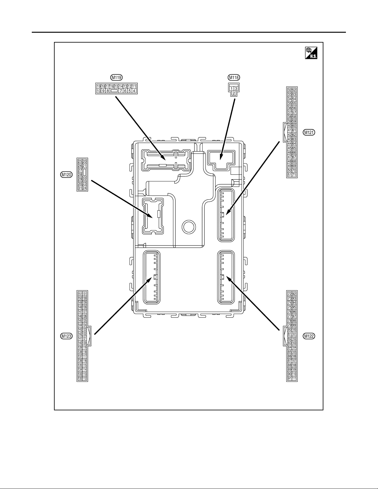
TERMINAL LAYOUT
BCM (BODY CONTROL MODULE)
PHYSICAL VALUES
JPMIA0062ZZ
INL-50
Page 51
< ECU DIAGNOSIS >
2007 G35 Sedan
Revision: October 2006
BCM (BODY CONTROL MODULE)
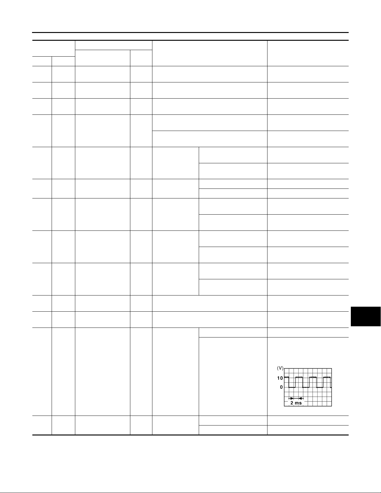
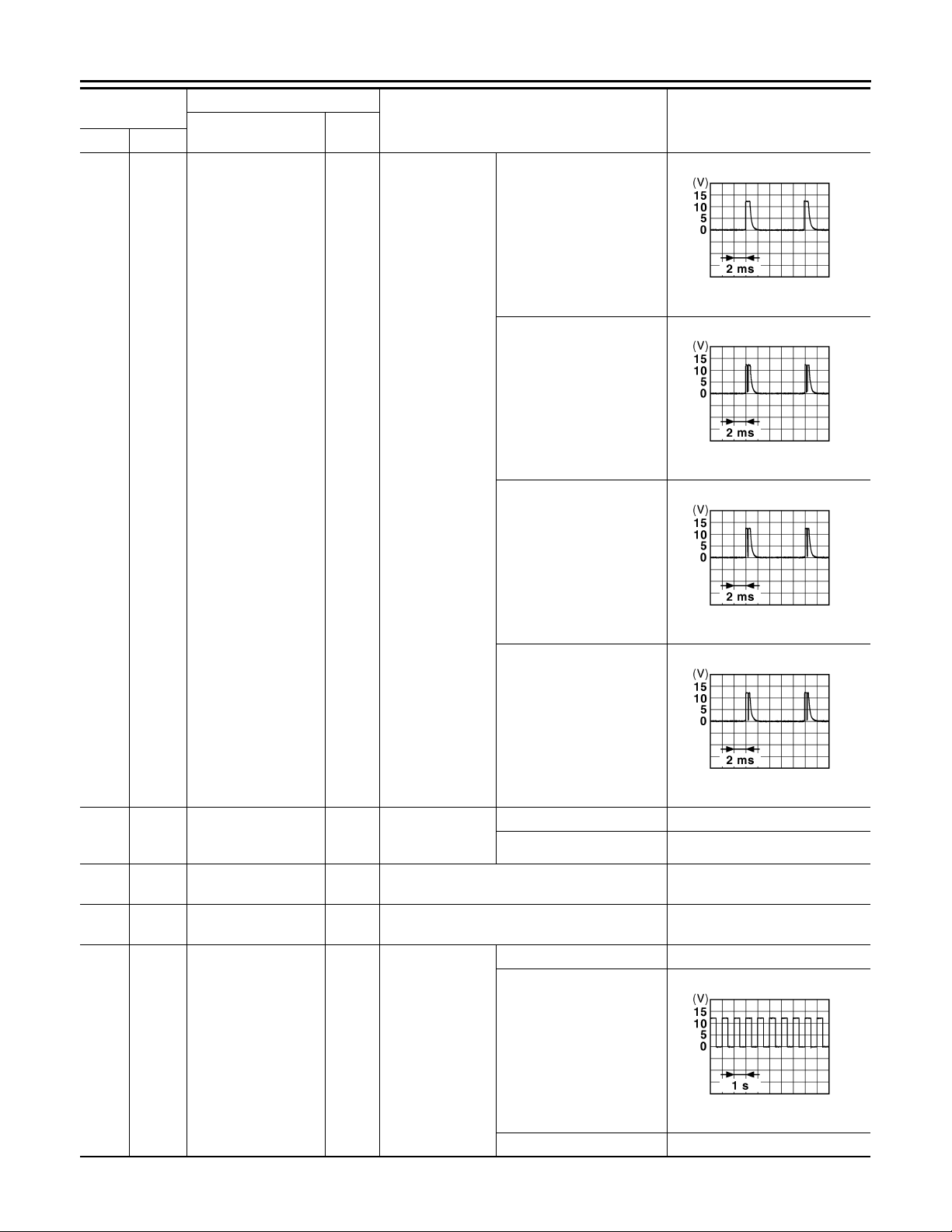
Terminal No.
(Wire color)
1
Ground Battery powe r supply Input Ignition switch OFF Battery voltage
(W)
2
Ground
(Y)
3
Ground
(O)
4
Ground
(LG)
5
Ground
(V)
7
Ground Step lamp Output Step lamp
(Y)
8
Ground
(V)
9
Ground
(G)
10
Ground
(BR)
11
Ground Battery powe r supply Input Ignition switch OFF Battery voltage
(R)
13
Ground Ground — Ignition switch ON 0 V
(B)
14
Ground
(W)
P/W power supply
(BAT)
P/W power supply
(RAP)
Interior room lamp
power supply
Passenger door UNLOCK
All doors, fuel lid
LOCK
Driver door, fuel lid
UNLOCK
Rear RH door and
rear LH door UNLOCK
Push-button ignition
switch illumination
ground
Description
Signal name
Input/
Output+–
Output Ignition switch OFF Battery voltage
Output Ignition switch ON Battery voltage
After passing the interior room lamp batte ry sav-
Output
Output Passenger door
Output All doors, fuel lid
Output
Output
Output Tail lamp
er operation time
Any other time after passing the interior room
lamp battery saver operation time
Driver door, fuel
lid
Rear RH door
and rear LH door
Condition
UNLOCK (Actuator is activated)
Other than UNLOCK (Actuator is not activated)
ON 0 V
OFF Battery voltage
LOCK (Actuator is activat-
ed)
Other than LOCK (Actuator
is not activated)
UNLOCK (Actuator is acti-
vated)
Other than UNLOCK (Actu-
ator is not activated)
UNLOCK (Actuator is acti-
vated)
Other than UNLOCK (Actu-
ator is not activated)
OFF 0 V
ON
Value
(Approx.)
0 V
Battery voltage
Battery voltage
0 V
Battery voltage
0 V
Battery voltage
0 V
Battery voltage
0 V
NOTE:
When the illumination brightening/dimming level is in the neutral
position
A
B
C
D
E
F
G
H
I
J
K
INL
M
N
15
Ground ACC indica tor lamp Output Ignition switch
(Y)
INL-51
OFF Battery voltage
ACC or ON 0 V
O
JSNIA0010GB
P
Page 52
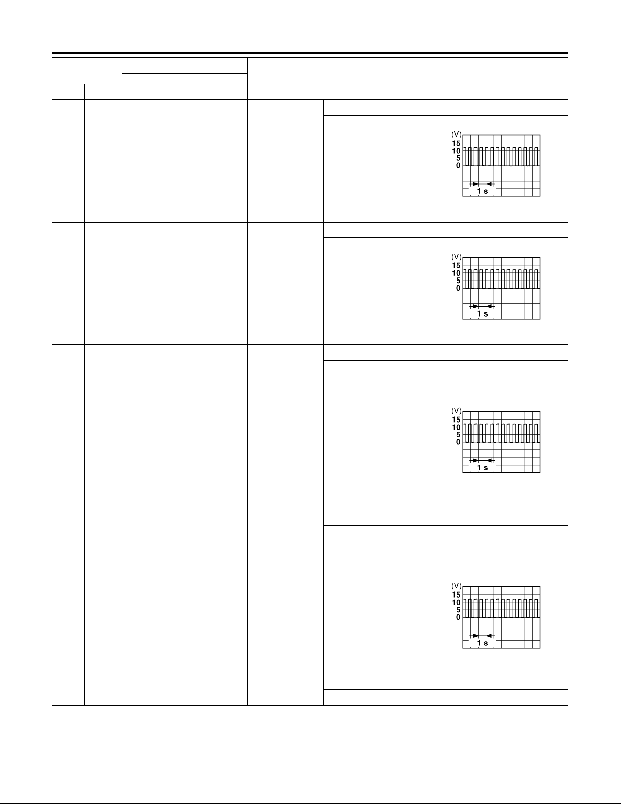
< ECU DIAGNOSIS >
2007 G35 Sedan
Revision: October 2006
BCM (BODY CONTROL MODULE)
Terminal No.
(Wire color)
17
Ground T urn signal (front RH) Output
(W)
18
Ground Turn signal (front LH) Output
(O)
19
(V)
Ground
Room lamp timer
control
Description
Signal name
Input/
Output+–
Output
Ignition switch
ON
Ignition switch
ON
Interior room
lamp
Condition
Turn signal switch OFF 0 V
Turn signal switch RH
Turn signal switch OFF 0 V
Turn signal switch LH
OFF Battery voltage
ON 0 V
Turn signal switch OFF 0 V
Value
(Approx.)
PKID0926E
6.5 V
PKID0926E
6.5 V
20
Ground Turn signal (rear RH) Output
(V)
23
Ground Trunk lid opening. Output Trunk lid
(G)
25
Ground Turn signal (rear LH) Output
(G)
30
Ground Trunk room lamp Output Trunk room lamp
(R)
Ignition switch
ON
Ignition switch
ON
Turn signal switch RH
Open (Trunk lid opene r actuator is activated)
Close (Trunk lid open er actuator is not activated)
Turn signal switch OFF 0 V
Turn signal switch LH
ON 0 V
OFF Battery voltage
Battery voltage
0 V
PKID0926E
6.5 V
PKID0926E
6.5 V
INL-52
Page 53
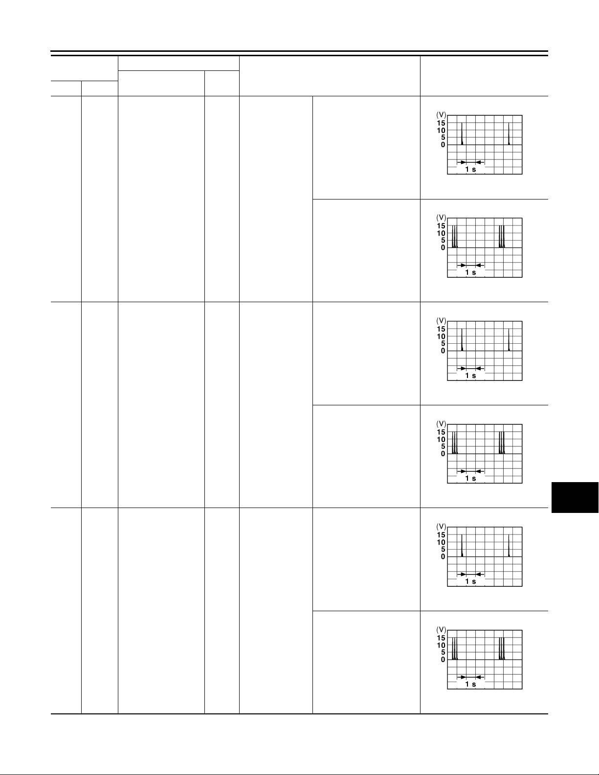
< ECU DIAGNOSIS >
B
B
B
B
B
B
2007 G35 Sedan
Revision: October 2006
BCM (BODY CONTROL MODULE)
Terminal No.
(Wire color)
34
Ground
(SB)
Description
Signal name
Trunk room antenna
1 (-)
Input/
Output+–
Output
Ignition switch
OFF
Condition
When Intelligent Key is in
the passenger compartment
When Intelligent Key is not
in the passenger compartment
When Intelligent Key is in
the passenger compartment
Value
(Approx.)
A
B
C
JMKIA0062G
D
E
F
JMKIA0063G
G
H
35
(V)
38
(B)
Ground
Ground
Trunk room antenna
1 (+)
Rear bumper antenna (-)
Output
Output
Ignition switch
OFF
When the trunk
lid request switch
is operated with
ignition switch
OFF
When Intelligent Key is not
in the passenger compartment
When Intelligent Key is in
the antenna detection area
When Intelligent Key is not
in the antenna detection
area
JMKIA0062G
JMKIA0063G
JMKIA0062G
I
J
K
INL
M
N
O
P
JMKIA0063G
INL-53
Page 54
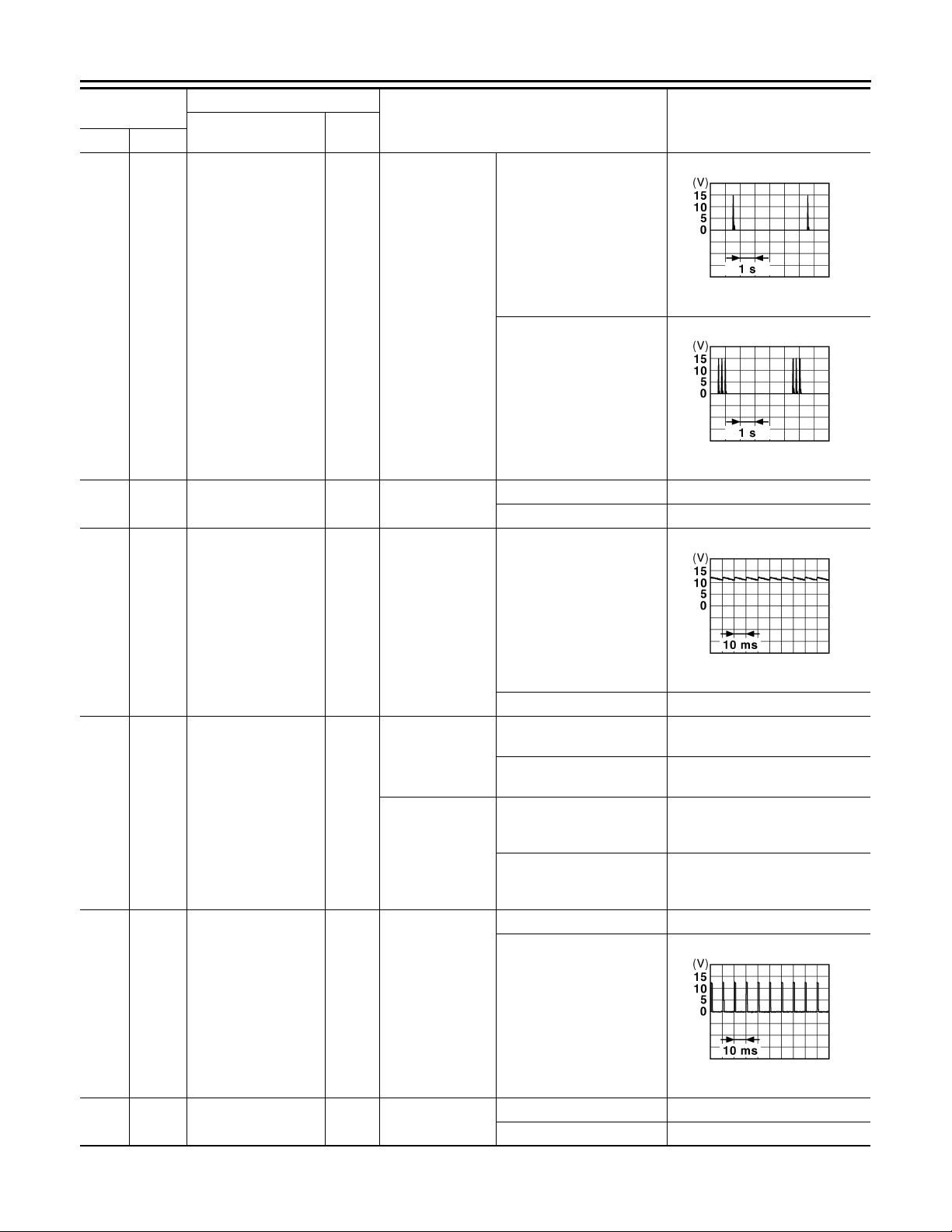
< ECU DIAGNOSIS >
B
B
B
2007 G35 Sedan
Revision: October 2006
BCM (BODY CONTROL MODULE)
Terminal No.
(Wire color)
39
Ground
(W)
47
Ground
(Y)
Description
Signal name
Rear bumper antenna (+)
Ignition relay (IPDM
E/R) control
Input/
Output+–
When the trunk
Output
lid request switch
is operated with
ignition switch
OFF
Output Ignition switch
Condition
When Intelligent Key is in
the antenna detection area
When Intelligent Key is not
in the antenna detection
area
OFF or ACC Battery voltage
ON 0 V
Value
(Approx.)
JMKIA0062G
JMKIA0063G
50
Ground
(R)
52
Ground Starter relay control Output
(SB)
61
Ground Trunk request switch Input
(W)
Trunk room lamp
switch
Input
Trunk room lamp
switch
Ignition switch
OFF (M/T models)
Ignition switch
ON (A/T models)
Trunk request
switch
OFF (Trunk is closed)
ON (Trunk is open) 0 V
When the clutch pedal is
depressed
When the clutch pedal is
not depressed
Battery voltage
0 V
When selector lever is in P
or N position and the brake
Battery voltage
is depressed
When selector lever is in P
or N position and the brake
0 V
is not depressed
ON (Pressed) 0 V
OFF (Not pressed)
JPMIA0011GB
11.8 V
64
Ground
(V)
Request switch buzzer
Output
Request switch
buzzer
INL-54
JPMIA0016G
1.0 V
Sounding 0 V
Not sounding Battery voltage
Page 55
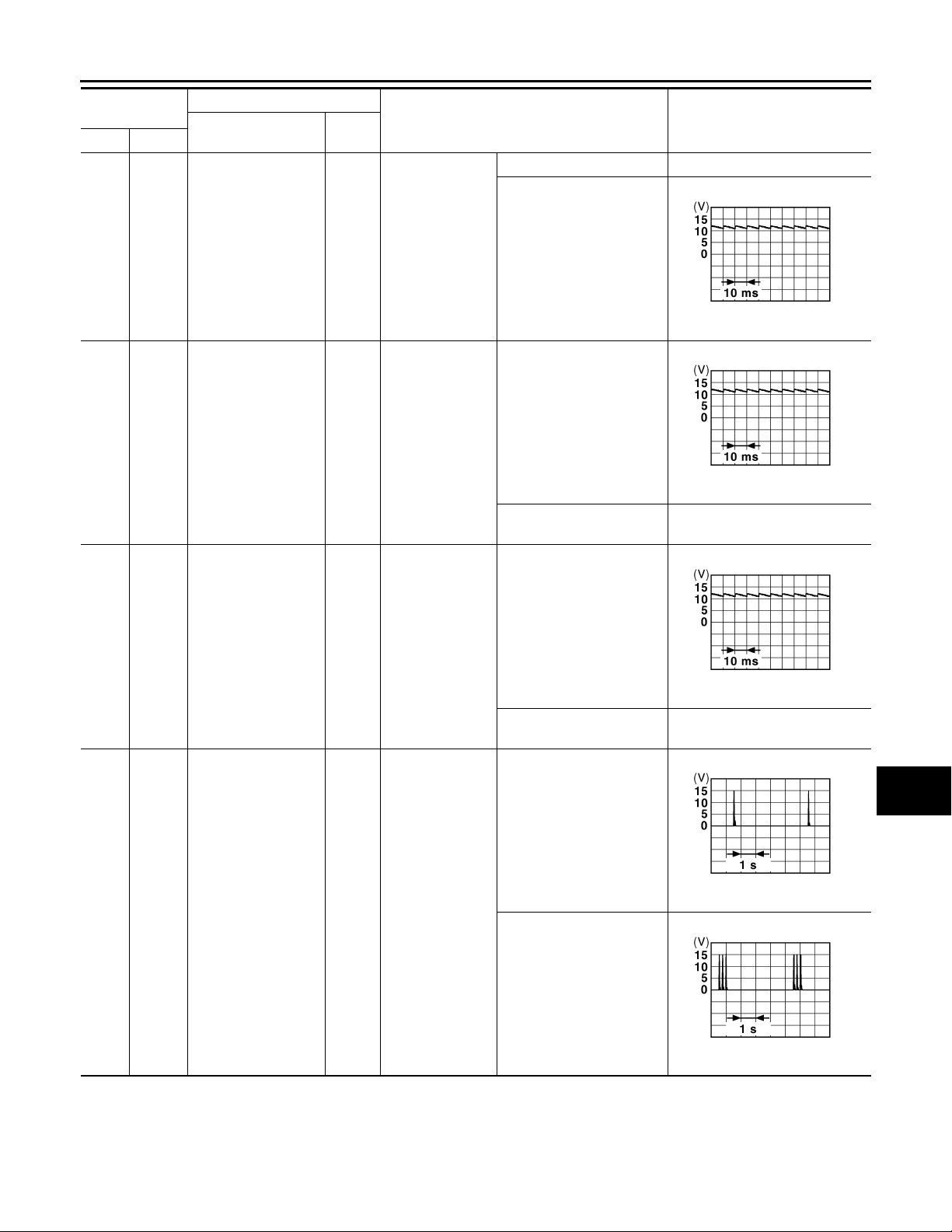
< ECU DIAGNOSIS >
B
B
2007 G35 Sedan
Revision: October 2006
BCM (BODY CONTROL MODULE)
Terminal No.
(Wire color)
67
(GR)
Ground
68
Ground Rear RH door switch Input
(BR)
Description
Signal name
Trunk lid opener
switch
Input/
Output+–
Input
Trunk lid opener
switch
Rear RH door
switch
Condition
Pressed 0 V
Not pressed
OFF (When rear RH door
closes)
ON (When rear RH door
opens)
0 V
Value
(Approx.)
11.8 V
11.8 V
JPMIA0011GB
JPMIA0011GB
A
B
C
D
E
F
G
H
69
Ground Rear LH door switch Input
(R)
72
(R)
Ground
Room antenna 2 (-)
(center console)
Output
Rear LH door
switch
Ignition switch
OFF
OFF (When rear LH door
closes)
ON (When rear LH door
opens)
When Intelligent Key is in
the passenger compartment
When Intelligent Key is not
in the passenger compartment
0 V
11.8 V
JPMIA0011GB
JMKIA0062G
JMKIA0063G
I
J
K
INL
M
N
O
P
INL-55
Page 56
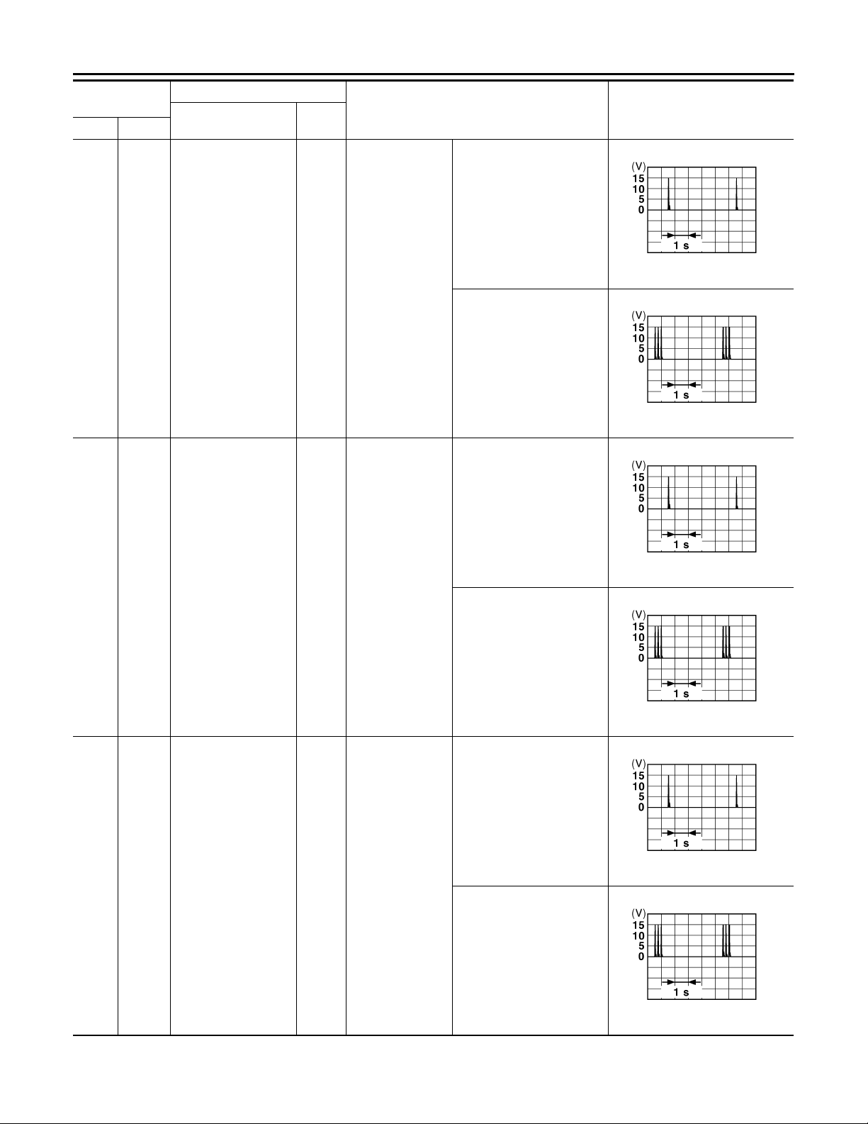
< ECU DIAGNOSIS >
B
B
B
B
B
B
2007 G35 Sedan
Revision: October 2006
BCM (BODY CONTROL MODULE)
Terminal No.
(Wire color)
73
Ground
(G)
Description
Signal name
Room antenna 2 (+)
(center console)
Input/
Output+–
Output
Ignition switch
OFF
Condition
When Intelligent Key is in
the passenger compartment
When Intelligent Key is not
in the passenger compartment
Value
(Approx.)
JMKIA0062G
JMKIA0063G
74
(SB)
75
(BR)
Ground
Ground
Passenger door antenna (-)
Passenger door antenna (+)
Output
Output
When the passenger door request switch is
operated with ignition switch OFF
When the passenger door request switch is
operated with ignition switch OFF
When Intelligent Key is in
the antenna detection area
JMKIA0062G
When Intelligent Key is not
in the antenna detection
area
JMKIA0063G
When Intelligent Key is in
the antenna detection area
JMKIA0062G
When Intelligent Key is not
in the antenna detection
area
JMKIA0063G
INL-56
Page 57
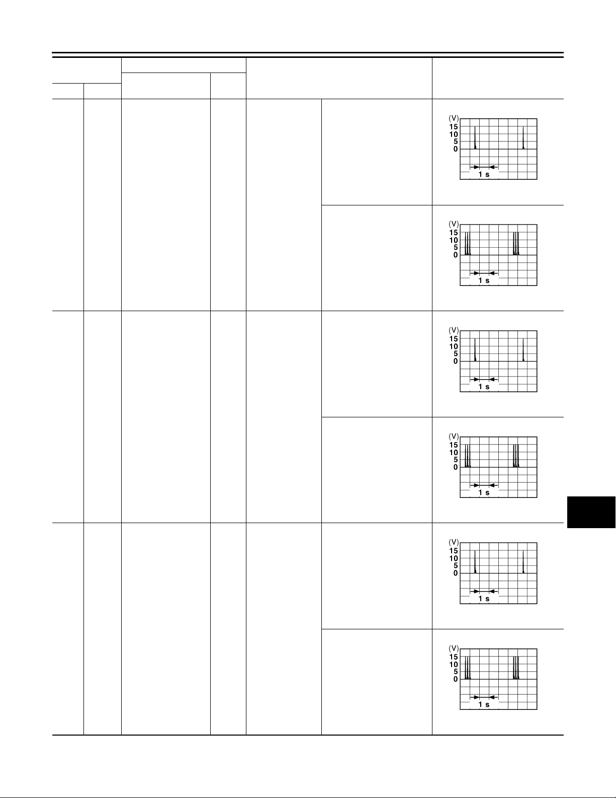
< ECU DIAGNOSIS >
B
B
B
B
B
B
2007 G35 Sedan
Revision: October 2006
BCM (BODY CONTROL MODULE)
Terminal No.
(Wire color)
76
Ground
(V)
Description
Signal name
Driver door antenna
(-)
Input/
Output+–
Output
When the driver
door request
switch is operated with ignition
switch OFF
Condition
When Intelligent Key is in
the antenna detection area
When Intelligent Key is not
in the antenna detection
area
When Intelligent Key is in
the antenna detection area
Value
(Approx.)
A
B
C
JMKIA0062G
D
E
F
JMKIA0063G
G
H
77
(LG)
78
(Y)
Ground
Ground
Driver door antenna
(+)
Room antenna (-) (instrument panel)
Output
Output
When the driver
door request
switch is operated with ignition
switch OFF
Ignition switch
OFF
When Intelligent Key is not
in the antenna detection
area
When Intelligent Key is in
the passenger compartment
When Intelligent Key is not
in the passenger compartment
JMKIA0062G
JMKIA0063G
JMKIA0062G
I
J
K
INL
M
N
O
P
JMKIA0063G
INL-57
Page 58
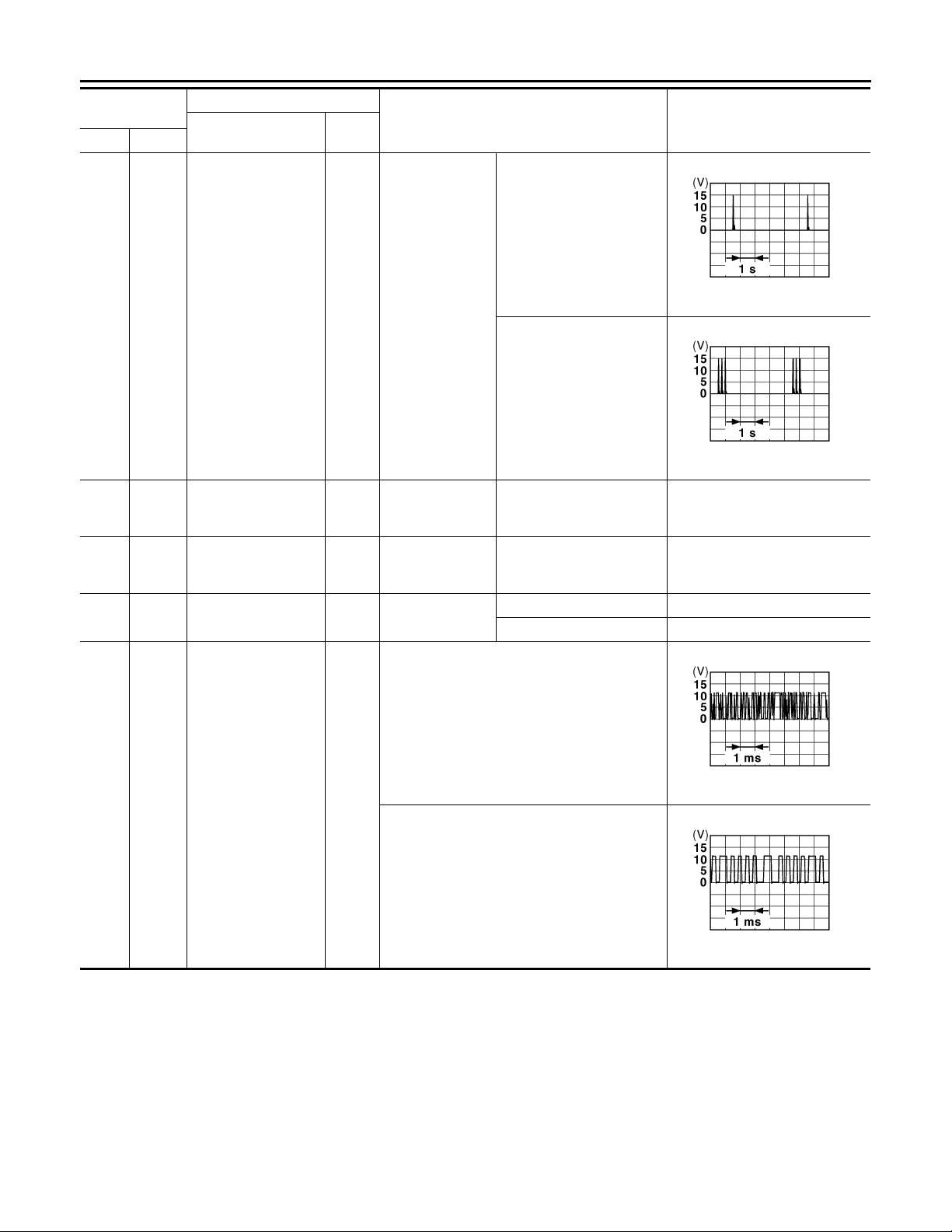
< ECU DIAGNOSIS >
B
B
B
B
2007 G35 Sedan
Revision: October 2006
BCM (BODY CONTROL MODULE)
Terminal No.
(Wire color)
79
Ground
(BR)
80
81
(W)
82
(R)
Ground
Ground
Ground
(GR)
Description
Signal name
Room antenna (+)
(instrument panel)
NATS antenna amp
(built in key slot)
NATS antenna amp
(built in key slot)
Ignition relay (relay
box) control
Input/
Output+–
Output
Input/
Output
Input/
Output
Ignition switch
OFF
During waiting
During waiting
Output Ignition switch
Condition
When Intelligent Key is in
the passenger compartment
When Intelligent Key is not
in the passenger compartment
Ignition switch is pressed
while inserting the Intelligent Key into the key slot.
Ignition switch is pressed
while inserting the Intelligent Key into the key slot.
Just after pressing ignition
switch. Pointer of tester should
move.
Just after pressing ignition
switch. Pointer of tester should
move.
OFF or ACC 0 V
ON Battery voltage
Value
(Approx.)
JMKIA0062G
JMKIA0063G
83
(Y)
Ground
Remote keyless entry
receiver signal
During waiting
JMKIA0064G
Input/
Output
When operating either button on Intelligent Key
JMKIA0065G
INL-58
Page 59
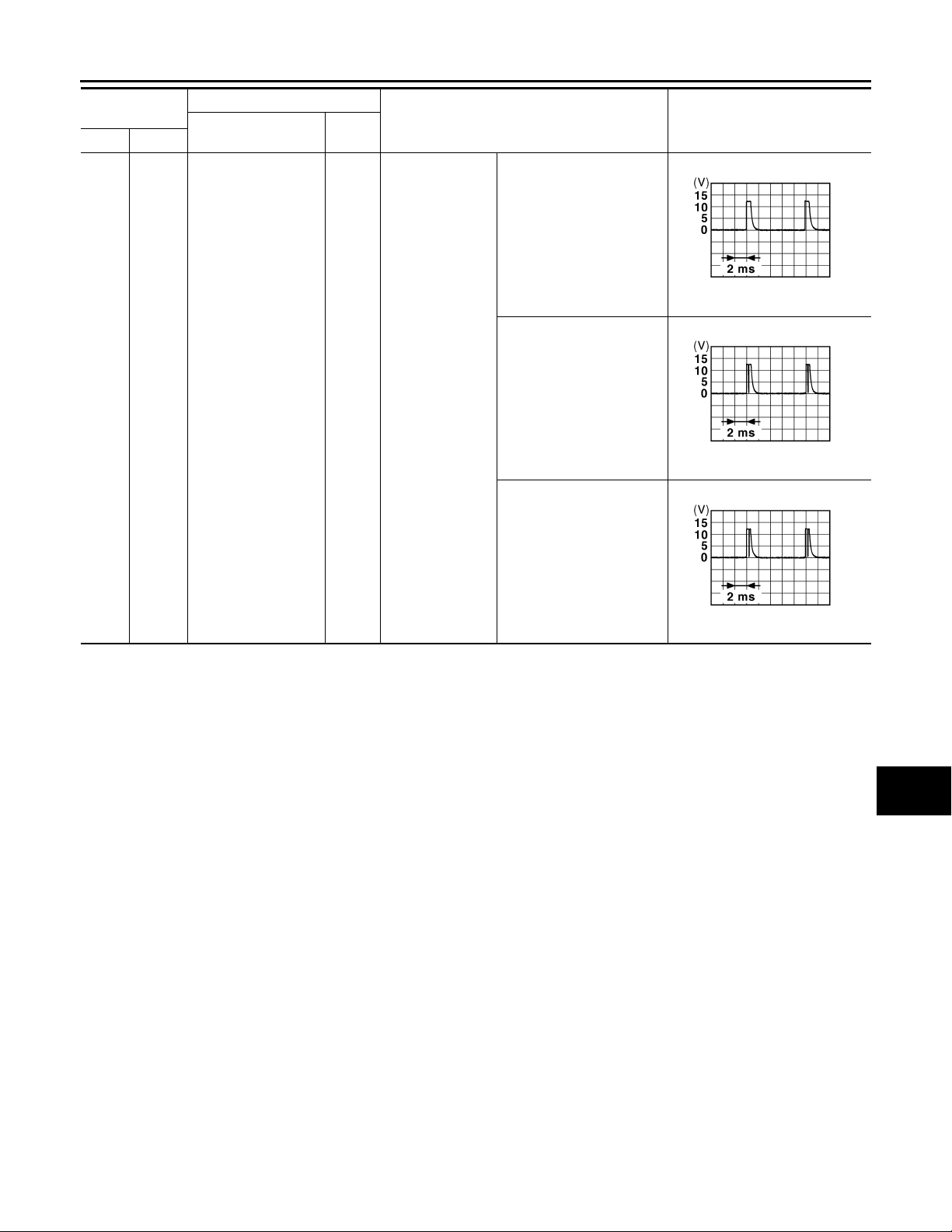
< ECU DIAGNOSIS >
B
B
B
2007 G35 Sedan
Revision: October 2006
BCM (BODY CONTROL MODULE)
Terminal No.
(Wire color)
87
Ground
(BR)
Description
Signal name
Combination switch
INPUT 5
Input/
Output+–
Input
Combination
switch
Condition
All switch OFF
(Wiper intermittent dial 4)
Front fog lamp switch ON
(Wiper intermittent dial 4)
Any of the conditions below
with all switch OFF
• Wiper intermittent dial 1
• Wiper intermittent dial 2
• Wiper intermittent dial 6
• Wiper intermittent dial 7
Value
(Approx.)
1.4 V
1.3 V
1.3 V
JPMIA0041G
JPMIA0037G
JPMIA0040G
A
B
C
D
E
F
G
H
I
J
K
INL
M
N
O
P
INL-59
Page 60
< ECU DIAGNOSIS >
B
B
B
B
B
2007 G35 Sedan
Revision: October 2006
BCM (BODY CONTROL MODULE)
Terminal No.
(Wire color)
88
Ground
(V)
Description
Signal name
Combination switch
INPUT 3
Input/
Output+–
Input
Combination
switch
Condition
All switch OFF
(Wiper intermittent dial 4)
Lighting switch HI
(Wiper intermittent dial 4)
Value
(Approx.)
JPMIA0041G
1.4 V
JPMIA0036G
1.3 V
89
Ground
(BR)
90
Ground CAN - L
(P)
91
Ground CAN - H
(L)
Push-button ignition
switch (push switch)
Input
Input/
Output
Input/
Output
Push-button ignition switch (push
switch)
Lighting switch 2ND
(Wiper intermittent dial 4)
JPMIA0037G
1.3 V
Any of the conditions below
with all switches OFF
• Wiper intermittent dial 1
• Wiper intermittent dial 2
• Wiper intermittent dial 3
JPMIA0040G
1.3 V
Pressed 0 V
Not pressed Battery voltage
——
——
OFF 0 V
92
Ground Key slot illumination Output
(LG)
Key slot illumination
Blinking
JPMIA0015G
6.5 V
ON Battery voltage
INL-60
Page 61
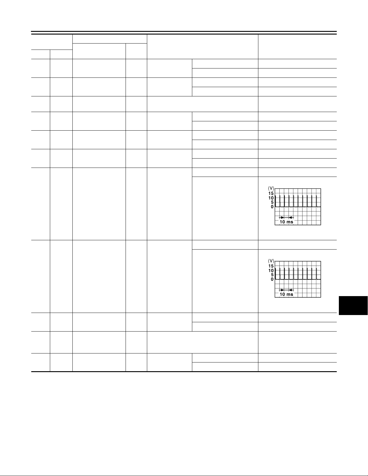
< ECU DIAGNOSIS >
B
B
2007 G35 Sedan
Revision: October 2006
BCM (BODY CONTROL MODULE)
Terminal No.
(Wire color)
93
Ground ON indicator lamp Output Ignition switch
(V)
95
Ground ACC relay control Output Ignition switch
(O)
96
97
(L)
98
(P)
99
(R)
100
(G)
Ground
Ground
Ground
Ground
Ground
(GR)
Description
Signal name
A/T device (detention
switch) power supply
Steering lock condition No. 1
Steering lock condition No. 2
Selector lever P position switch
Passenger door request switch
Input/
Output+–
Output — Battery voltage
Input Steering lock
Input Steering lock
Input Selector lever
Input
Passenger door
request switch
Condition
OFF or ACC 0 V
ON Battery voltage
OFF 0 V
ACC or ON Battery voltage
LOCK status 0 V
UNLOCK status Battery voltage
LOCK status Battery voltage
UNLOCK status 0 V
P position 0 V
Any position other than P Battery voltage
ON (Pressed) 0 V
OFF (Not pressed)
(Approx.)
Value
A
B
C
D
E
F
G
H
101
(SB)
102
(O)
103
(LG)
106
(W)
Ground
Ground
Ground
Ground
Driver door request
switch
Blower fan motor relay control
Remote keyless entry
receiver power supply
Steering wheel lock
unit power supply
ON (Pressed) 0 V
Input
Output Ignition switch
Output Ignition switch OFF Battery voltage
Output Ignition switch
Driver door request switch
OFF (Not pressed)
OFF or ACC 0 V
ON Battery voltage
OFF or ACC Battery voltage
ON 0 V
1.0 V
1.0 V
JPMIA0016G
I
J
K
JPMIA0016G
INL
M
N
O
P
INL-61
Page 62
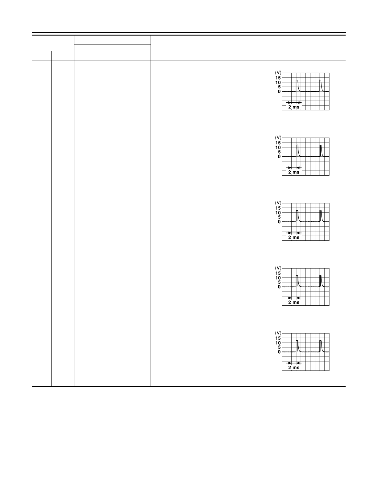
< ECU DIAGNOSIS >
B
B
B
B
B
2007 G35 Sedan
Revision: October 2006
BCM (BODY CONTROL MODULE)
Terminal No.
(Wire color)
107
Ground
(LG)
Description
Signal name
Combination switch
INPUT 1
Input/
Output+–
Input
Combination
switch
(Wiper intermittent dial 4)
Condition
All switch OFF
Turn signal switch LH
Turn signal switch RH
Value
(Approx.)
JPMIA0041G
1.4 V
JPMIA0037G
1.3 V
Front wiper switch LO
Front washer switch ON
JPMIA0036G
1.3 V
JPMIA0038G
1.3 V
JPMIA0039G
1.3 V
INL-62
Page 63
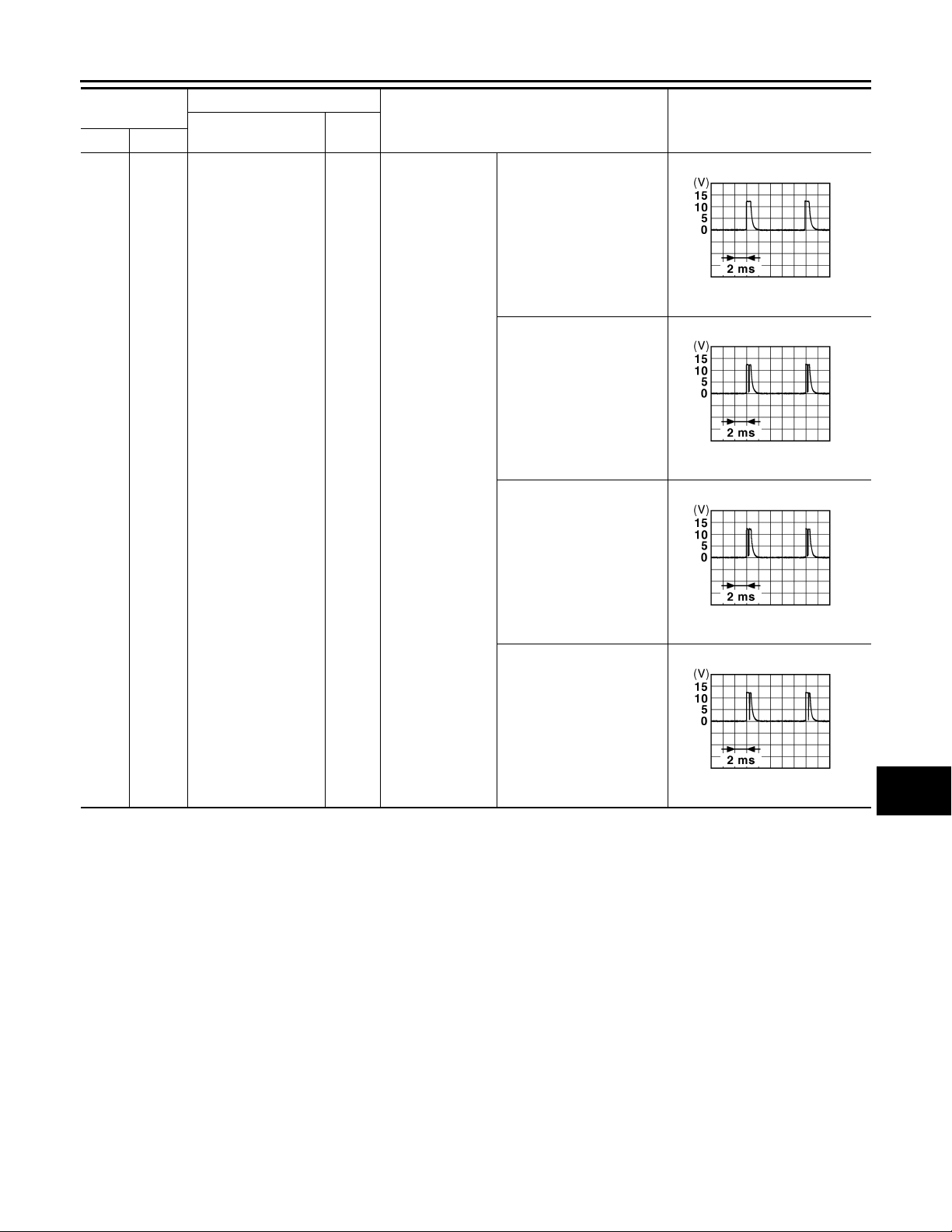
< ECU DIAGNOSIS >
B
B
B
B
2007 G35 Sedan
Revision: October 2006
BCM (BODY CONTROL MODULE)
Terminal No.
(Wire color)
108
Ground
(R)
Description
Signal name
Combination switch
INPUT 4
Input/
Output+–
Input
Combination
switch
Condition
All switch OFF
(Wiper intermittent dial 4)
Lighting switch AUTO
(Wiper intermittent dial 4)
Lighting switch 1ST
(Wiper intermittent dial 4)
Value
(Approx.)
1.4 V
1.3 V
A
B
C
JPMIA0041G
D
E
F
JPMIA0038G
G
H
Any of the conditions below
with all switches OFF
• Wiper intermittent dial 1
• Wiper intermittent dial 5
• Wiper intermittent dial 6
1.3 V
1.3 V
JPMIA0036G
JPMIA0039G
I
J
K
INL
M
N
O
P
INL-63
Page 64
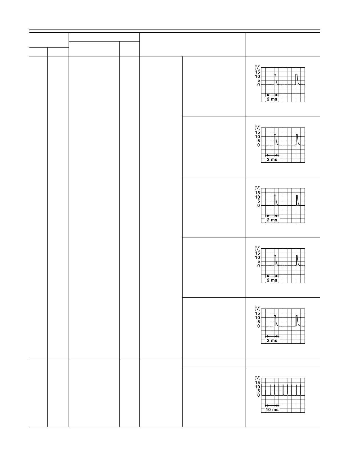
< ECU DIAGNOSIS >
B
B
B
B
B
B
2007 G35 Sedan
Revision: October 2006
BCM (BODY CONTROL MODULE)
Terminal No.
(Wire color)
109
Ground
(Y)
Description
Signal name
Combination switch
INPUT 2
Input/
Output+–
Input
Combination
switch
(Wiper intermittent dial 4)
Condition
All switch OFF
Lighting switch PASS
Lighting switch 2ND
Value
(Approx.)
JPMIA0041G
1.4 V
JPMIA0037G
1.3 V
110
Ground Hazard switch Input Hazard switch
(G)
JPMIA0036G
1.3 V
Front wiper switch INT
JPMIA0038G
1.3 V
Front wiper switch HI
JPMIA0040G
1.3 V
Pressed 0 V
Not pressed
JPMIA0012G
1.1 V
INL-64
Page 65
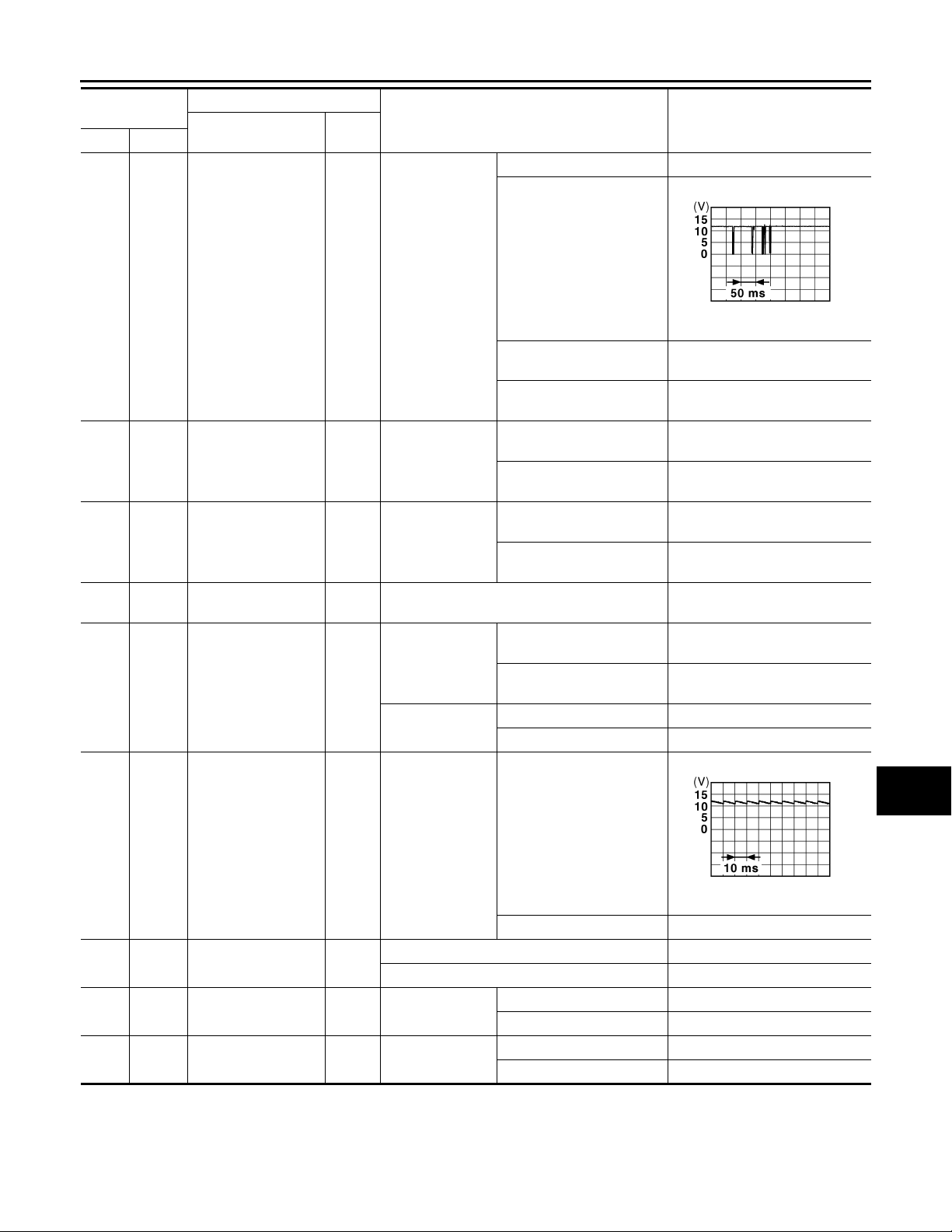
< ECU DIAGNOSIS >
B
2007 G35 Sedan
Revision: October 2006
BCM (BODY CONTROL MODULE)
Terminal No.
(Wire color)
111
Ground
(Y)
113
Ground Optical sensor signal Input
(P)
114
Ground
(R)
116
Ground Stop lamp switch 1 Input — Battery voltage
(SB)
118
Ground Stop lamp switch 2 Input
(P)
Steering lock unit
communication
Clutch interlock
switch
Description
Signal name
Input/
Output+–
Input/
Output
Input
Steering lock
Ignition switch
ON
Clutch interlock
switch
Stop lamp switch
ICC brake hold
relay (With ICC)
Condition
LOCK status Battery voltage
LOCK or UNLOCK
For 15 seconds after UNLOCK
15 seconds or later after
UNLOCK
When bright outside of the
vehicle
When dark outside of the
vehicle
OFF (Clutch pedal is not
depressed)
ON (Clutch pedal is depressed)
OFF (Brake pedal is not
depressed)
ON (Brake pedal is depressed)
OFF 0 V
ON Battery voltage
(Approx.)
Battery voltage
0 V
Close to 5 V
Close to 0 V
0 V
Battery voltage
0 V
Battery voltage
Value
JMKIA0066G
A
B
C
D
E
F
G
H
I
J
K
119
Ground
(SB)
121
Ground Key slot switch Input
(R)
122
Ground ACC feedback signal Input Ignition switch
(V)
123
Ground IGN feedback signal Input Ignition switch
(W)
Front door lock assembly driver side
(unlock sensor)
Input Driver door
When Intelligent Key is inserted into key slot Battery voltage
When Intelligent Key is not inserted into key sl ot 0 V
INL-65
LOCK status
UNLOCK status 0 V
OFF 0 V
ACC or ON Battery voltage
OFF or ACC 0 V
ON Battery voltage
INL
M
JPMIA0011GB
11.8 V
N
O
P
Page 66
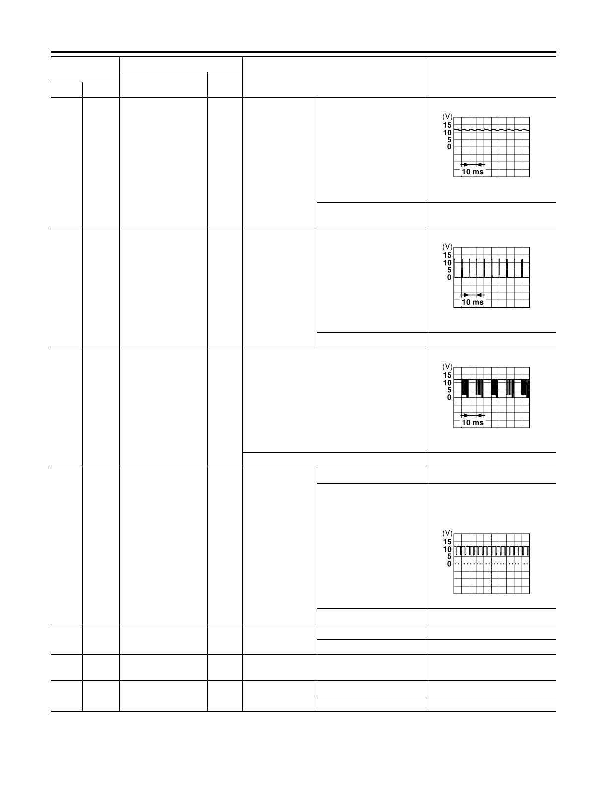
< ECU DIAGNOSIS >
B
B
B
2007 G35 Sedan
Revision: October 2006
BCM (BODY CONTROL MODULE)
Terminal No.
(Wire color)
124
Ground
(LG)
129
Ground
(O)
Description
Signal name
Passenger door
switch
Trunk lid opener cancel switch
Input/
Output+–
Input
Input
Passenger door
switch
Trunk lid opener
cancel switch
Condition
OFF (When passenger
door closes)
ON (When passenger door
opens)
CANCEL
ON 0 V
Value
(Approx.)
JPMIA0011GB
11.8 V
0 V
JPMIA0012G
1.1 V
132
(V)
133
(W)
134
(GR)
137
(O)
138
(V)
Ground
Ground
Power window switch
communication
Push-button ignition
switch illumination
Input/
Output
Output
Ground LOCK indicator lamp Output
Ground
Ground
Receiver and sensor
ground
Receiver and sensor
power supply output
Input Ignition switch ON 0 V
Output Ignition switch
Ignition switch ON
Ignition switch OFF or ACC 0 V
ON (When tail lamps OFF) 5.5 V
NOTE:
The pulse width of this wave is
varied by the illumination bri ght-
ening/dimming level.
Push-button ignition switch illumi-
ON (When tail lamps ON)
nation
OFF 0 V
LOCK indicator
lamp
ON 0 V
OFF Battery voltage
OFF 0 V
ACC or ON 5.0 V
JPMIA0013G
10.2 V
JPMIA0159G
INL-66
Page 67
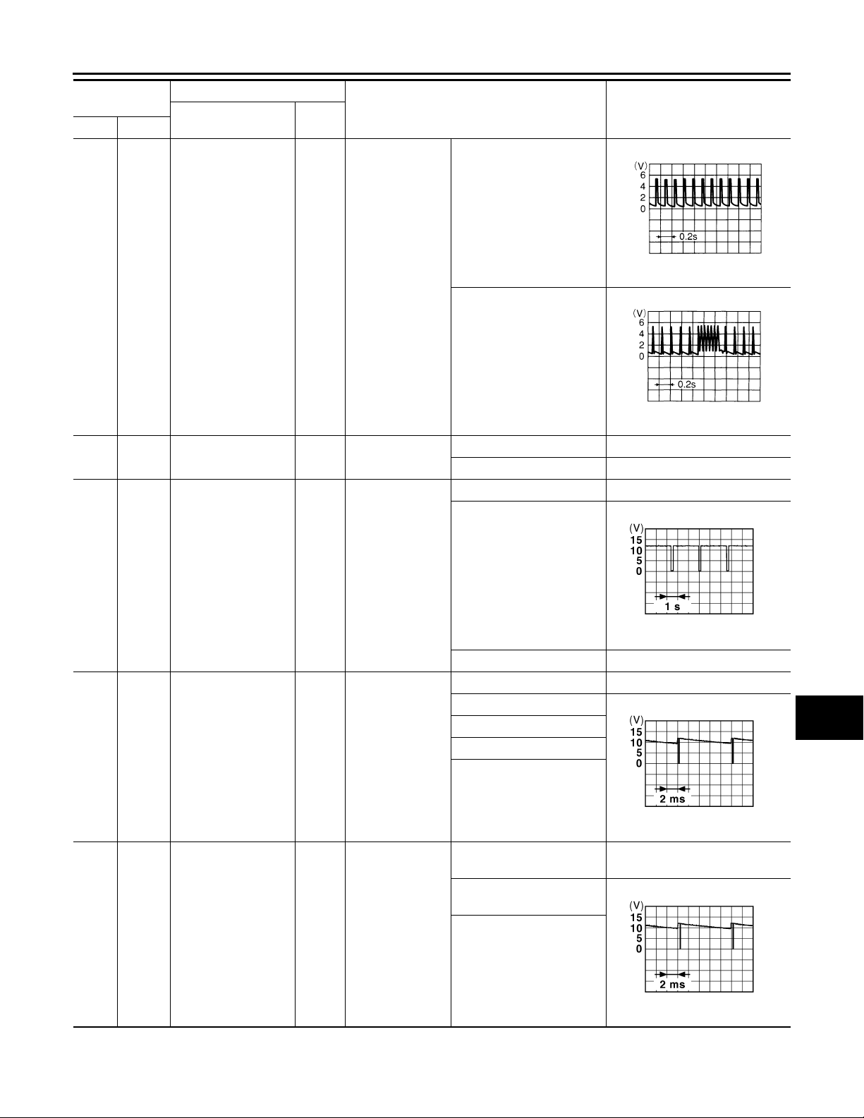
< ECU DIAGNOSIS >
B
B
B
2007 G35 Sedan
Revision: October 2006
BCM (BODY CONTROL MODULE)
Terminal No.
(Wire color)
139
Ground
(L)
140
(GR)
Ground
Description
Signal name
Tire pressure receiver signal
Selector lever P/N
position signal
Input/
Output+–
Input/
Output
Input Selector lever
Ignition switch
ON
Condition
Stan dby state
When receiving the signal
from the transmitter
P or N position 12.0 V
Except P and N positions 0 V
ON 0 V
Value
(Approx.)
A
B
C
OCC3881D
D
E
F
OCC3880D
G
H
141
(G)
142
(O)
143
(P)
Ground
Ground
Ground
Security indicator s ignal
Combination switch
OUTPUT 5
Combination switch
OUTPUT 1
Output Security indicator
Combination
Output
Output
switch
(Wiper intermittent dial 4)
Combination
switch
Blinking
OFF Battery voltage
All switch OFF 0 V
Lighting switch 1ST
Lighting switch HI
Lighting switch 2ND
Turn signal switch RH
All switch OFF
(Wiper intermittent dial 4)
Front wiper switch HI
(Wiper intermittent dial 4)
Any of the conditions below
with all switch OFF
• Wiper intermittent dial 1
• Wiper intermittent dial 2
• Wiper intermittent dial 3
• Wiper intermittent dial 6
• Wiper intermittent dial 7
0 V
10.7 V
11.3 V
10.7 V
I
J
JPMIA0014G
K
INL
M
JPMIA0031G
N
O
P
JPMIA0032G
INL-67
Page 68
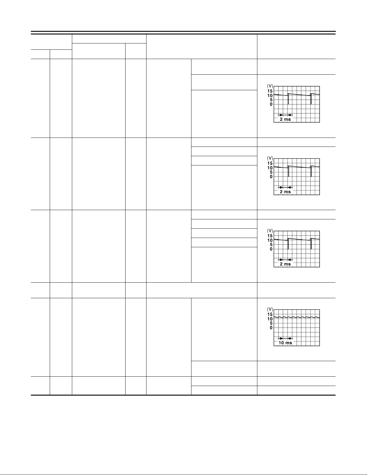
< ECU DIAGNOSIS >
B
B
B
2007 G35 Sedan
Revision: October 2006
BCM (BODY CONTROL MODULE)
Terminal No.
(Wire color)
144
Ground
(G)
145
Ground
(L)
146
Ground
(SB)
149
Ground
(W)
Description
Signal name
Combination switch
OUTPUT 2
Combination switch
OUTPUT 3
Combination switch
OUTPUT 4
Tire pressure warning check switch
Input/
Condition
Output+–
All switch OFF
(Wiper intermittent dial 4)
Front washer switch ON
(Wiper intermittent dial 4)
Output
Combination
switch
Any of the conditions below
with all switches OFF
• Wiper intermittent dial 1
• Wiper intermittent dial 5
• Wiper intermittent dial 6
All switches OFF 0 V
Front wiper switch INT
Front wiper switch LO
Lighting switch AUTO
Output
Combination
switch
(Wiper intermittent dial 4)
All switch OFF 0 V
Front fog lamp switch ON
Lighting switch 2ND
Lighting switch PASS
Output
Combination
switch
(Wiper intermittent dial 4)
Turn signal switch LH
Input — 5 V
Value
(Approx.)
0 V
JPMIA0033G
10.7 V
JPMIA0034G
10.7 V
JPMIA0035G
10.7 V
150
(GR)
Ground Driver door switch Input
151
Ground
(G)
Rear window defogger relay
Output
Driver door
switch
Rear window defogger
INL-68
OFF (When driver door
closes)
ON (When driver door
opens)
0 V
Active 0 V
Not activated Battery voltage
JPMIA0011GB
11.8 V
Page 69
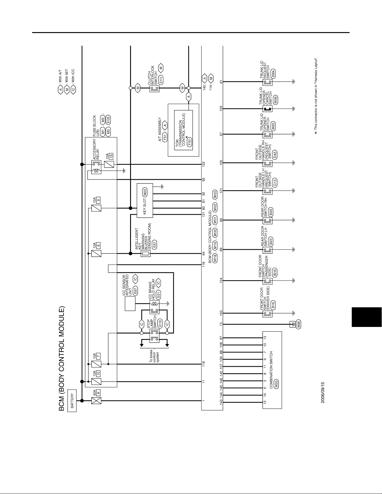
BCM (BODY CONTROL MODULE)
B
2007 G35 Sedan
Revision: October 2006
< ECU DIAGNOSIS >
Wiring Diagram — BCM — INFOID:0000000000962600
A
B
C
D
E
F
G
H
J
K
INL
M
N
O
I
JCMWA0005G
P
INL-69
Page 70
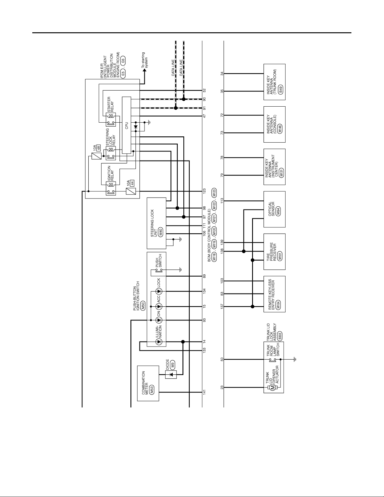
< ECU DIAGNOSIS >
B
2007 G35 Sedan
Revision: October 2006
BCM (BODY CONTROL MODULE)
JCMWA0006G
INL-70
Page 71
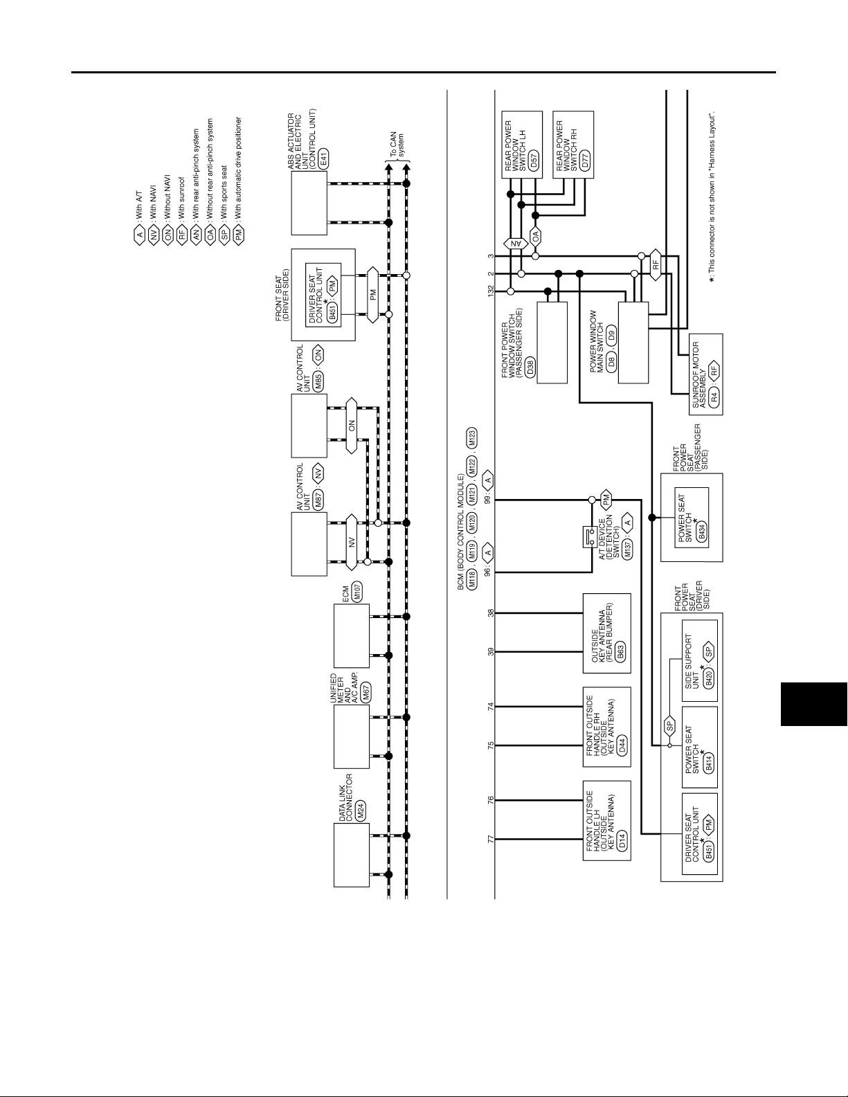
< ECU DIAGNOSIS >
B
2007 G35 Sedan
Revision: October 2006
BCM (BODY CONTROL MODULE)
A
B
C
D
E
F
G
H
J
K
INL
M
N
O
I
JCMWA0007G
P
INL-71
Page 72
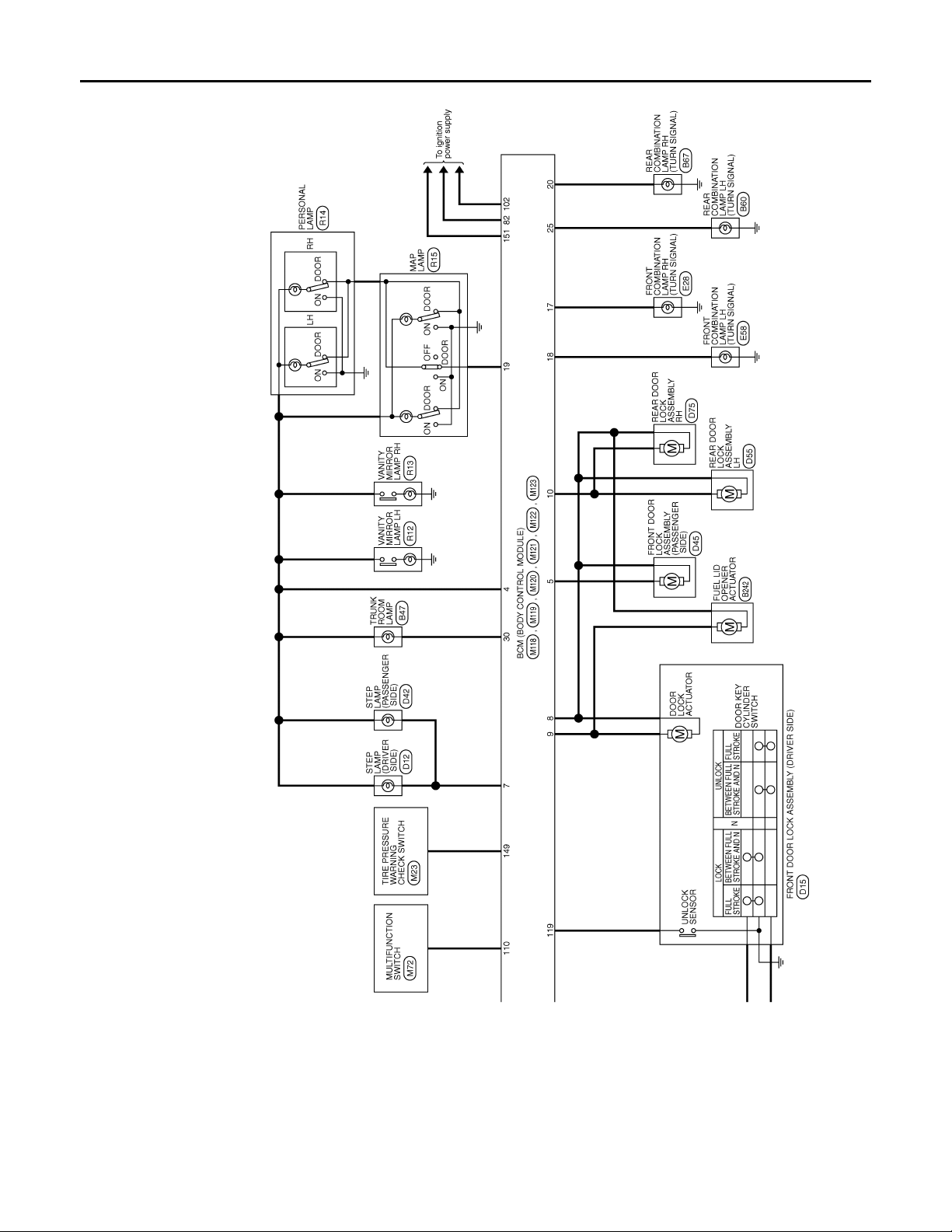
< ECU DIAGNOSIS >
B
2007 G35 Sedan
Revision: October 2006
BCM (BODY CONTROL MODULE)
JCMWA0008G
INL-72
Page 73
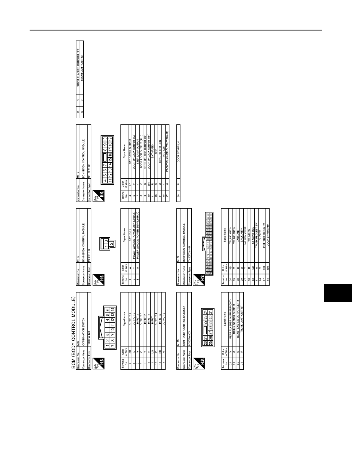
< ECU DIAGNOSIS >
B
2007 G35 Sedan
Revision: October 2006
BCM (BODY CONTROL MODULE)
A
B
C
D
E
F
G
H
J
K
INL
M
N
O
I
JCMWA0009G
P
INL-73
Page 74
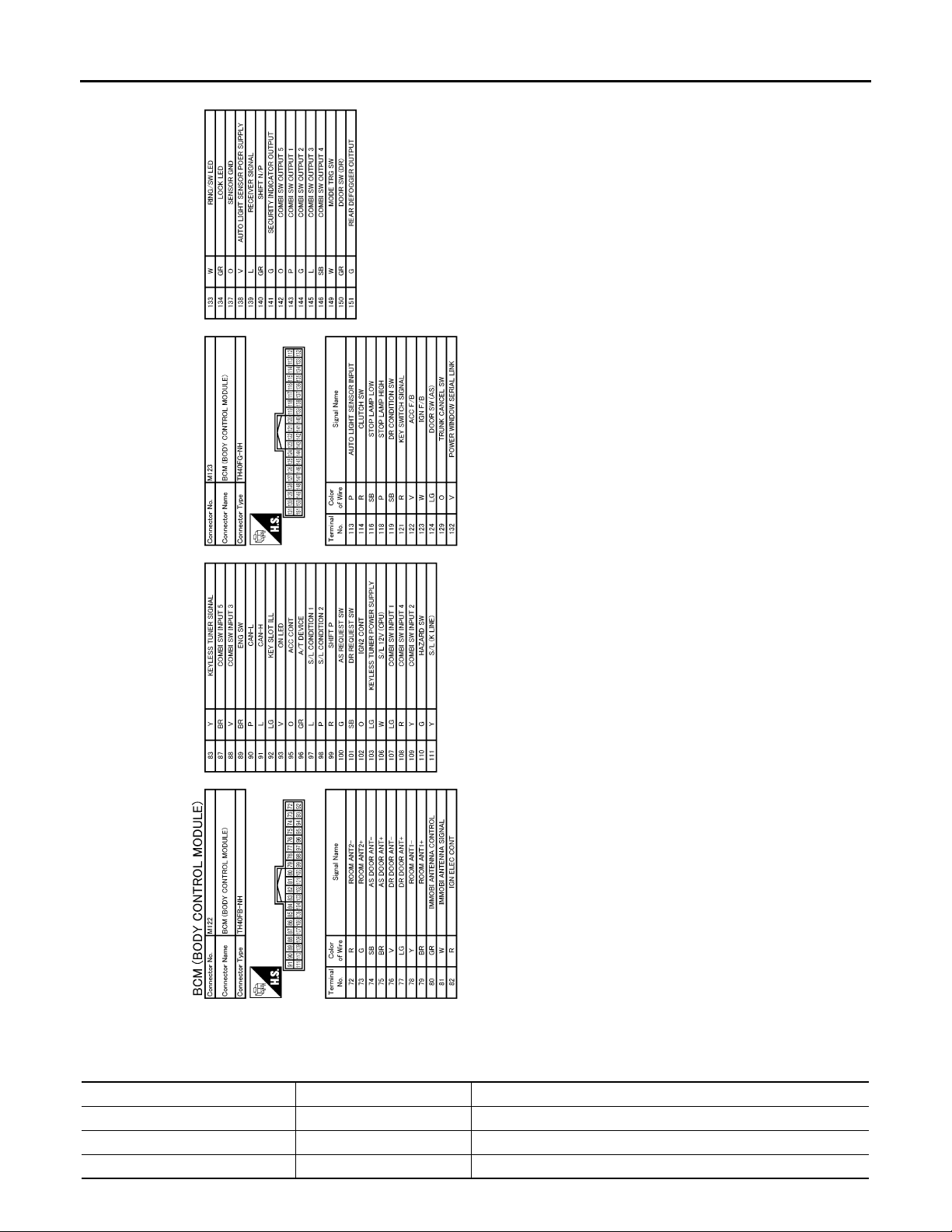
< ECU DIAGNOSIS >
B
2007 G35 Sedan
Revision: October 2006
BCM (BODY CONTROL MODULE)
Fail Safe
Display contents of CONSULT Fail-safe Cancellation
B2013: ID DISCORD BCM-S/L Inhibit engine cranking Erase DTC
B2014: CHAIN OF S/L-BCM Inhibit engine cranking Erase DTC
B2190: NATS ANTTENA AMP Inhibit engine cranking Erase DTC
JCMWA0010G
INFOID:0000000000962601
INL-74
Page 75

< ECU DIAGNOSIS >
2007 G35 Sedan
Revision: October 2006
BCM (BODY CONTROL MODULE)
Display contents of CONSULT Fail-safe Cancellation
B2191: DIFFERENCE OF KEY Inhib it en gin e cra nk ing Erase DTC
B2192: ID DISCORD BCM-ECM Inhibit engin e cra nk ing Erase DTC
B2193: CHAIN OF BCM-ECM Inhibit engine cranking Erase DTC
B2557: VEHICLE SPEED Inhibit steering lock
B2560: STARTER CONT RELAY Inhibit engine cranking
B2563: HI VOLTAGE
B2601: SHIFT POSITION Inhibit steering lock
B2602: SHIFT POSITION Inhibit steering lock
B2603: SHIFT POSI STATUS Inhibit steering lock
B2604: PNP SW Inhibit steering lock
B2605: PNP SW Inhibit steering lock
B2606: S/L RELAY Inhibit engine cranking
B2607: S/L RELAY Inhibit engine cranking
• Inhibit engine cranking
• Inhibit steering lock
When normal vehicle speed signals have been received from ABS
actuator and electric unit (control unit) for 500 ms
500 ms after the followin g CAN signal communication stat us has
become consistent
• Starter control relay signal
• Starter relay status signal
500 ms after the power supply voltage decreases to less than 18 V
500 ms after the foll owin g si gnal re cept ion status becomes consis-
tent
• Selector lever P position switch signal
• P range signal (CAN)
5 seconds after the following BCM recognition conditions are ful-
filled
• Ignition switch is in the ON position
• Selector lever P position switch signal: Except P position (b attery
voltage)
• Vehicle speed: 4 /h or more
500 ms after the following BCM recognition conditions are fulfilled
• Ignition switch is in the ON position
• Selector lever P position switch signal: Except P position (b attery
voltage)
• Selector lever P/N position signal: Except P and N positions (0 V)
500 ms after any of the followin g BCM recognit ion conditi ons is fulfilled
•Status 1
- Ignition switch is in the ON position
- Selector lever P/N position signal: P and N position (battery voltage)
- P range signal or N range signal (CAN): ON
•Status 2
- Ignition switch is in the ON position
- Selector lever P/N position signal: Except P and N positions (0 V)
- P range signal and N range signal (CAN): OFF
500 ms after any of the followin g BCM recognit ion conditi ons is fulfilled
• Ignition switch is in the ON position
- Power position: IGN
- Selector lever P/N position signal: Except P and N positions (0 V)
- Interlock/PNP switch signal (CAN): OFF
•Status 2
- Ignition switch is in the ON position
- Selector lever P/N position signal: P or N position (battery voltage)
- PNP switch signal (CAN): ON
500 ms after the followin g CAN signal communication stat us has
become consistent
• Steering lock relay signal (Request signal)
• Steering lock relay signal (Condition signal)
500 ms after the followin g CAN signal communication stat us has
become consistent
• Steering lock relay signal (Request signal)
• Steering lock relay signal (Condition signal)
A
B
C
D
E
F
G
H
I
J
K
INL
M
N
O
P
INL-75
Page 76

BCM (BODY CONTROL MODULE)
2007 G35 Sedan
Revision: October 2006
< ECU DIAGNOSIS >
Display contents of CONSULT Fail-safe Cancellation
500 ms after the following signal communication status becomes
B2608: STARTER RELAY Inhibit engine cranking
B2609: S/L STATUS
B260A: IGNITION RELAY Inhibit engine cranking
B260F: ENG STATE SIG LOST
B2612: S/L STATUS
B2617: STARTER RELAY CIRC Inhibit engine cranking
B2618: BCM Inhibit engine cranking
B2619: BCM Inhibit engine cranking
B261E: VEHICLE TYPE Inhibit engine cranking BCM initialization
B26E1: ENG STATE NO RECIV Inhibit engine cranking
• Inhibit engine cranking
• Inhibit steering lock
Maintains the power supply
position attained at the time
of DTC detection
• Inhibit engine cranking
• Inhibit steering lock
consistent
• Starter motor relay control signal
• Starter relay status signal (CAN)
When the following steering lock conditions agree
• BCM steering lock control status
• Steering lock condition No. 1 signal status
• Steering lock condition No. 2 signal status
500 ms after the following conditions are fulfilled
• IGN relay (IPDM E/R) control signal: OFF (Battery voltage)
• Ignition ON signal (CAN to IPDM E/R): OFF (Request signal)
• Ignition ON signal (CAN from IPDM E/R): OFF (Condition signal)
When any of the following conditions is fulfilled
• Power position changes to ACC
• Receives engine status signal (CAN)
When any of the following conditions is fulfilled
• Steering lock unit status signal (CAN) is received normally
• The BCM steering lock control status matches the steering lock
status recognized by the steering lock unit status signal (CAN
from IPDM E/R)
1 second after the st arter motor relay control insi de BCM becomes
normal
1 second after the ignition relay (IPDM E/R) control inside BCM becomes normal
1 second after the steering lock unit power supply ou tput control inside BCM becomes normal
When any of the following conditions is fulfilled
• Power position changes to ACC
• Receives engine status signal (CAN)
DTC Inspection Priority Chart
INFOID:0000000000962602
If some DTCs are displayed at the same time, perform inspections one by one based on the following priority
chart.
Priority DTC
1
2
3
• B2562: LOW VOLTAGE
• B2563: HI VOLTAGE
• U1000: CAN COMM CIRCUIT
• U1010: CONTROL UNIT (CAN)
• B2190: NATS ANTTENA AMP
• B2191: DIFFERENCE OF KEY
• B2192: ID DISCORD BCM-ECM
• B2193: CHAIN OF BCM-ECM
INL-76
Page 77

< ECU DIAGNOSIS >
2007 G35 Sedan
Revision: October 2006
BCM (BODY CONTROL MODULE)
Priority DTC
• B2013: ID DISCORD BCM-S/L
• B2014: CHAIN OF S/L-BCM
• B2553: IGNITION RELAY
• B2555: STOP LAMP
• B2556: PUSH-BTN IGN SW
• B2557: VEHICLE SPEED
• B2560: STARTER CONT RELAY
• B2601: SHIFT POSITION
• B2602: SHIFT POSITION
• B2603: SHIFT POSI STATUS
• B2604: PNP SW
• B2605: PNP SW
• B2606: S/L RELAY
• B2607: S/L RELAY
• B2608: STARTER RELAY
• B2609: S/L STATUS
4
5
6
• B260A: IGNITION RELAY
• B260B: STEERING LOCK UNIT
• B260C: STEERING LOCK UNIT
• B260D: STEERING LOCK UNIT
• B260F: ENG STATE SIG LOST
• B2611: ACC RELAY
• B2612: S/L STATUS
• B2614: ACC RELAY CIRC
• B2615: BLOWER RELAY CIRC
• B2616: IGN RELAY CIRC
• B2617: STARTER RELAY CIRC
• B2618: BCM
• B2619: BCM
• B261A: PUSH-BTN IGN SW
• B261E: VEHICLE TYPE
• B26E1: ENG STATE NO RECIV
• C1729: VHCL SPEED SIG ERR
• U0415: VEHICLE SPEED SIG
• C1704: LOW PRESSURE FL
• C1705: LOW PRESSURE FR
• C1706: LOW PRESSURE RR
• C1707: LOW PRESSURE RL
• C1708: [NO DATA] FL
• C1709: [NO DATA] FR
• C1710: [NO DATA] RR
• C1711: [NO DATA] RL
• C1712: [CHECKSUM ERR] FL
• C1713: [CHECKSUM ERR] FR
• C1714: [CHECKSUM ERR] RR
• C1715: [CHECKSUM ERR] RL
• C1716: [PRESSDATA ERR] FL
• C1717: [PRESSDATA ERR] FR
• C1718: [PRESSDATA ERR] RR
• C1719: [PRESSDATA ERR] RL
• C1720: [CODE ERR] FL
• C1721: [CODE ERR] FR
• C1722: [CODE ERR] RR
• C1723: [CODE ERR] RL
• C1724: [BATT VOLT LOW] FL
• C1725: [BATT VOLT LOW] FR
• C1726: [BATT VOLT LOW] RR
• C1727: [BATT VOLT LOW] RL
• C1734: CONTROL UNIT
• B2621: INSIDE ANTENNA
• B2622: INSIDE ANTENNA
• B2623: INSIDE ANTENNA
A
B
C
D
E
F
G
H
I
J
K
INL
M
N
O
P
DTC Index INFOID:0000000000962603
INL-77
Page 78

BCM (BODY CONTROL MODULE)
2007 G35 Sedan
Revision: October 2006
< ECU DIAGNOSIS >
NOTE:
Details of time display
• CRNT: Displays when there is a malfunction now or after returning to the normal condition until turning ignition switch OFF → ON again.
• 1 - 39: Displayed if any previous malfunction is present when current condition is normal. It increases like 1
→ 2 → 3...38 → 39 after returning to the normal condition whenever ignition switch OFF → ON. The counter
remains at 39 even if the number of cycles exceeds it. It is counted from 1 again when turning ignition switch
OFF → ON after returning to the normal condition if the malfunction is detected again.
CONSULT display Fail-safe
No DTC is detected.
further testing
may be required.
U1000: CAN COMM CIRCUIT — — — BCS-33
U1010: CONTROL UNIT (CAN) — — — BCS-34
U0415: VEHICLE SPEED SIG — — — BCS-35
B2013: ID DISCORD BCM-S/L × ——SEC-43
B2014: CHAIN OF S/L-BCM × ——SEC-44
B2190: NATS ANTTENA AMP × ——SEC-37
B2191: DIFFERENCE OF KEY × ——SEC-40
B2192: ID DISCORD BCM-ECM × ——SEC-41
B2193: CHAIN OF BCM-ECM × ——SEC-42
B2553: IGNITION RELAY — — — PCS-48
B2555: STOP LAMP — — — SEC-47
B2556: PUSH-BTN IGN SW — × — SEC-49
B2557: VEHICLE SPEED ××— SEC-51
B2560: STARTER CONT RELAY ××— SEC-52
B2562: LOW VOLTAGE — — — BCS-36
B2563: HI VOLTAGE ××— BCS-37
B2601: SHIFT POSITION ××— SEC-53
B2602: SHIFT POSITION ××— SEC-56
B2603: SHIFT POSI STATUS ××— SEC-58
B2604: PNP SW ××— SEC-61
B2605: PNP SW ××— SEC-63
B2606: S/L RELAY ××— SEC-65
B2607: S/L RELAY ××— SEC-66
B2608: STARTER RELAY ××— SEC-68
B2609: S/L STATUS ××— SEC-70
B260A: IGNITION RELAY ××— PCS-50
B260B: STEERING LOCK VNIT — × — SEC-74
B260C: STEERING LOCK VNIT — × — SEC-75
B260D: STEERING LOCK VNIT — × — SEC-76
B260F: ENG STATE SIG LOST ××— SEC-77
B2611: ACC RELAY — — — PCS-52
B2612: S/L STATUS ××— SEC-79
B2614: ACC RELAY CIRC — × — PCS-54
B2615: BLOWER RELAY CIRC — × — PCS-57
————
Intelligent Key
warning lamp ON
Tire pressure
monitor warning
lamp ON
Reference page
INL-78
Page 79

< ECU DIAGNOSIS >
2007 G35 Sedan
Revision: October 2006
BCM (BODY CONTROL MODULE)
CONSULT display Fail-safe
B2616: IGN RELAY CIRC — × — PCS-60
B2617: STARTER RELAY CIRC ××— SEC-83
B2618: BCM ××— PCS-63
B2619: BCM ××— SEC-85
B261A: PUSH-BTN IGN SW — × — SEC-86
B261E: VEHICLE TYPE ×
B2621: INSIDE ANTENNA — — — DLK-58
B2622: INSIDE ANTENNA — — — DLK-60
B2623: INSIDE ANTENNA — — — DLK-62
B26E1: ENG STATE NO RES ××— SEC-78
C1704: LOW PRESSURE FL — — × WT-14
C1705: LOW PRESSURE FR — — × WT-14
C1706: LOW PRESSURE RR — — × WT-14
C1707: LOW PRESSURE RL — — × WT-14
C1708: [NO DATA] FL — — × WT-16
C1709: [NO DATA] FR — — × WT-16
C1710: [NO DATA] RR — — × WT-16
C1711: [NO DATA] RL — — × WT-16
C1712: [CHECKSUM ERR] FL — — × WT-19
C1713: [CHECKSUM ERR] FR — — × WT-19
C1714: [CHECKSUM ERR] RR — — × WT-19
C1715: [CHECKSUM ERR] RL — — × WT-19
C1716: [PRESSDATA ERR] FL — — × WT-22
C1717: [PRESSDATA ERR] FR — — × WT-22
C1718: [PRESSDATA ERR] RR — — × WT-22
C1719: [PRESSDATA ERR] RL — — × WT-22
C1720: [CODE ERR] FL — — × WT-24
C1721: [CODE ERR] FR — — × WT-24
C1722: [CODE ERR] RR — — × WT-24
C1723: [CODE ERR] RL — — × WT-24
C1724: [BATT VOLT LOW] FL — — × WT-27
C1725: [BATT VOLT LOW] FR — — × WT-27
C1726: [BATT VOLT LOW] RR — — × WT-27
C1727: [BATT VOLT LOW] RL — — × WT-27
C1729: VHCL SPEED SIG ERR — — × WT-30
C1734: CONTROL UNIT — — × WT-31
Intelligent Key
warning lamp ON
× (Turn ON for 15
seconds)
Tire pressure
monitor warning
lamp ON
— SEC-88
Reference page
A
B
C
D
E
F
G
H
I
J
K
INL
M
N
O
P
INL-79
Page 80
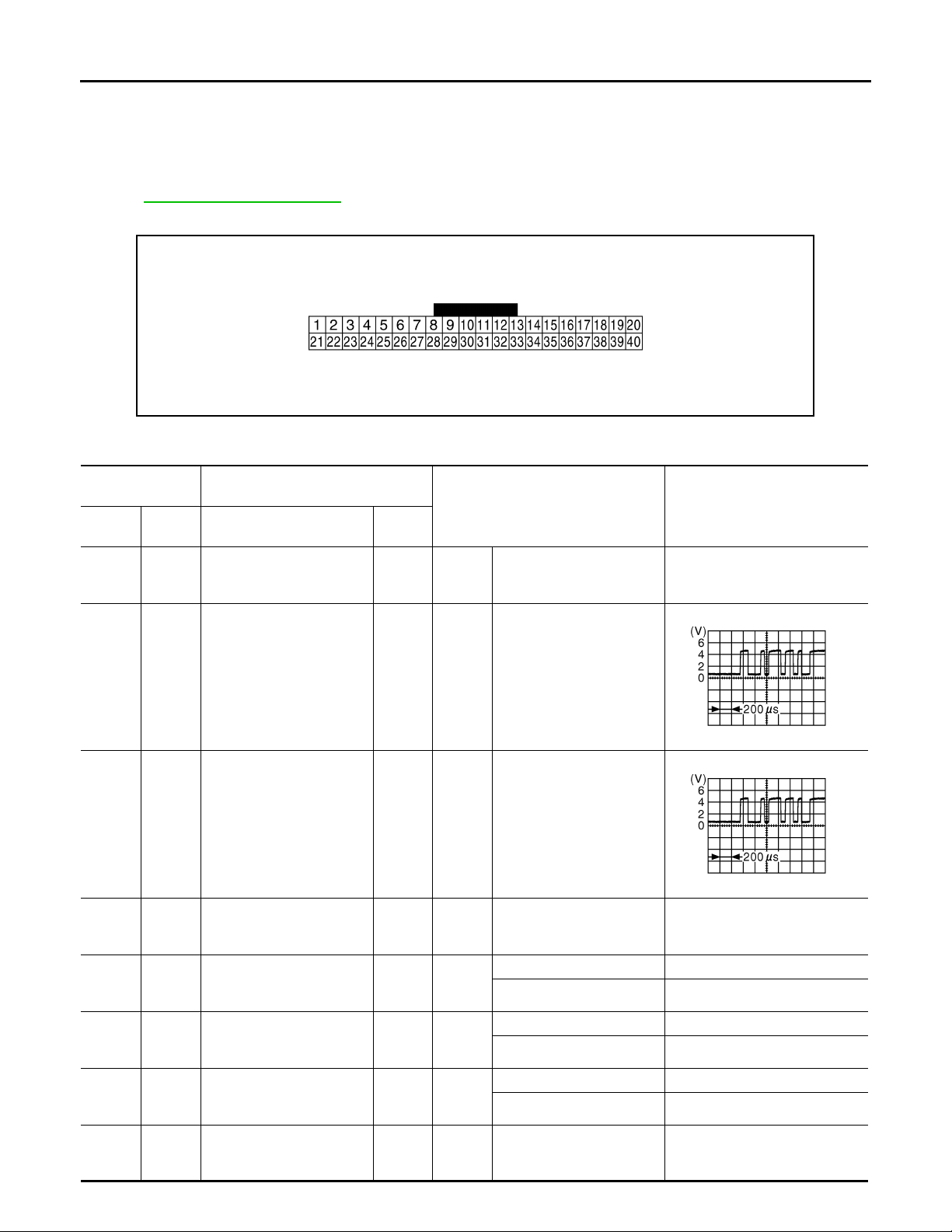
COMBINATION METER
2007 G35 Sedan
Revision: October 2006
< ECU DIAGNOSIS >
COMBINATION METER
Reference Value INFOID:0000000000962604
VALUES ON THE DAIAGNOSIS TOOL
Refer to MWI-80, "Reference Value".
TERMINAL LAYOUT
JSNIA0096ZZ
PHYSICAL VALUES
Term inal No.
(Wire color)
+ – Signal name
1
(GR)
(LG)
(GR)
(B)
(W)
(LG)
(G)
(B)
Ground Battery power supply Input
2
Ground
3
Ground
5
Ground Ground —
6
Ground Alternator signal Input
7
Ground Air bag signal Input
10
Ground Security signal Input
15
Ground Ground —
Communication signal
(METER→ AMP.)
Communication signal
(AMP.→ METER)
Description
Input/
Output
Output
Input
Ignition
switch
OFF
Ignition
switch
ON
Ignition
switch
ON
Ignition
switch
ON
Ignition
switch
ON
Ignition
switch
ON
Ignition
switch
OFF
Ignition
switch
ON
Condition
— Battery voltage
—
—
—0 V
Charge warning lamp ON 0 V
Charge warning lamp OFF 12 V
Air bag warning lamp ON 4 V
Air bag warning lamp OFF 0 V
Security warning lamp ON 0 V
Security warning lamp OFF 12 V
—0 V
Value
(Approx.)
JSNIA0027GB
JSNIA0027GB
INL-80
Page 81
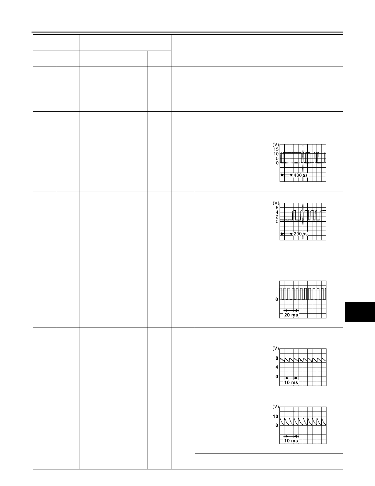
< ECU DIAGNOSIS >
2007 G35 Sedan
Revision: October 2006
COMBINATION METER
Terminal No.
(Wire color)
+ – Signal name
16
Ground Meter control switch ground —
(B)
21
(R)
(BR)
Ground Ignition signal Input
22
Ground Ground —
(B)
24
25
(Y)
Ground
Ground
Communication signal
(LCD→ AMP.)
Communication signal
(AMP.→ LCD)
Description
Input/
Output
Output
Input
Ignition
switch
ON
Ignition
switch
ON
Ignition
switch
ON
Ignition
switch
ON
Ignition
switch
ON
Condition
Value
(Approx.)
A
B
—0 V
C
—12 V
—0 V
D
E
—
JSNIA0028GB
F
G
H
—
26
(R)
27
(V)
Ground
Ground Parking brake switch signal Input
Vehicle speed signal
(8-pulse)
Input
Ignition
switch
ON
Ignition
switch
ON
NOTE:
The maximum voltage varies depending on the specification
(destination unit).
Speedome ter operated
[When vehicle speed is approx. 40 km/h (25 MPH)]
Parking brake ON 0 V
Parking brake OFF
JSNIA0027GB
JSNIA0012GB
JSNIA0007GB
I
J
K
INL
M
N
O
P
28
(W)
Ground
Brake fluid level switch signal
Input
Ignition
switch
ON
INL-81
Brake fluid level is normal.
The brake fluid level is lower than the low level
JSNIA0008GB
0 V
Page 82
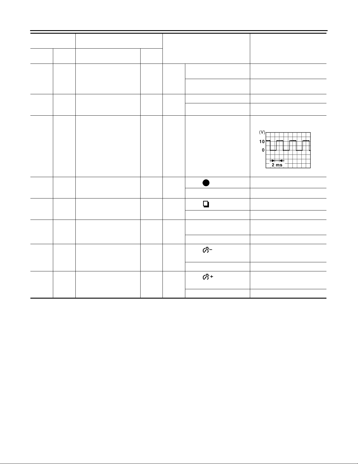
< ECU DIAGNOSIS >
2007 G35 Sedan
Revision: October 2006
COMBINATION METER
Term inal No.
(Wire color)
+ – Signal name
29
(SB)
31
(L)
34
(R)
36
(LG)
37
(SB)
38
(L)
Ground
Ground Washer level swit ch signal Input
Ground Illumination control signal Output
(B)
(B)
(B)
Seat belt buckle switch signal (driver side)
16
Select switch signal Input
16
Enter switch signal Input
16
Trip A/B reset switch signal In pu t
Description
Input/
Output
Input
Ignition
switch
ON
Ignition
switch
ON
Ignition
switch
ON
Ignition
switch
ON
Ignition
switch
ON
Ignition
switch
ON
Condition
When driver seat belt is fastened
When driver seat belt is unfastened
Washer level switch ON 0 V
Washer level switch OFF 5 V
NOTE:
When brightness level is midway
Lighting switch ON, then
operate the illumination
control switch.
When is pressed
Other than the above 5 V
When is pressed
Other than the above 5 V
When trip A/B reset switch
is pressed
Other than the above 5 V
Value
(Approx.)
12 V
0 V
0 V
0 V
0 V
JSNIA0010GB
39
(P)
40
(O)
16
(B)
16
(B)
Illumination control switch
signal (–)
Illumination control switch
signal (+)
Input
Input
Ignition
switch
ON
Ignition
switch
ON
When switch is
pressed
Other than the above 5 V
When switch is
pressed
Other than the above 5 V
0 V
0 V
INL-82
Page 83
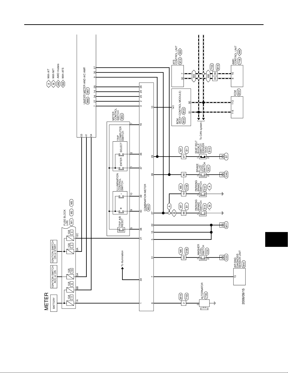
COMBINATION METER
B
2007 G35 Sedan
Revision: October 2006
< ECU DIAGNOSIS >
Wiring Diagram — METER — INFOID:0000000000962605
A
B
C
D
E
F
G
H
J
K
INL
M
N
O
I
JCNWA0001G
P
INL-83
Page 84
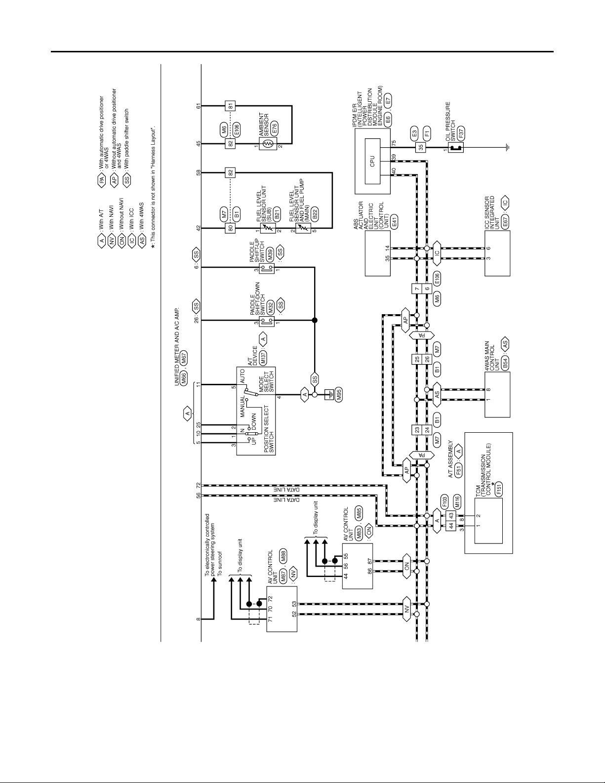
< ECU DIAGNOSIS >
B
2007 G35 Sedan
Revision: October 2006
COMBINATION METER
JCNWA0002G
INL-84
Page 85
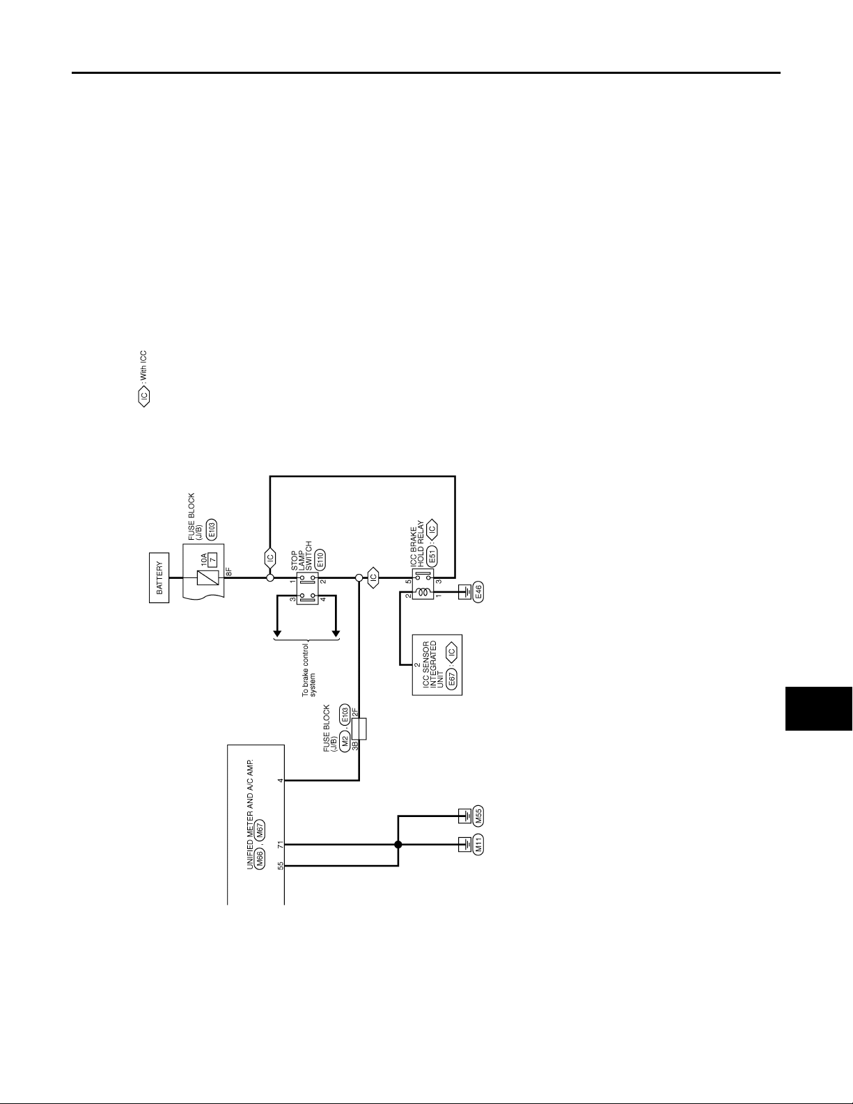
< ECU DIAGNOSIS >
B
2007 G35 Sedan
Revision: October 2006
COMBINATION METER
A
B
C
D
E
F
G
H
J
K
INL
M
N
O
I
JCNWA0003G
P
INL-85
Page 86
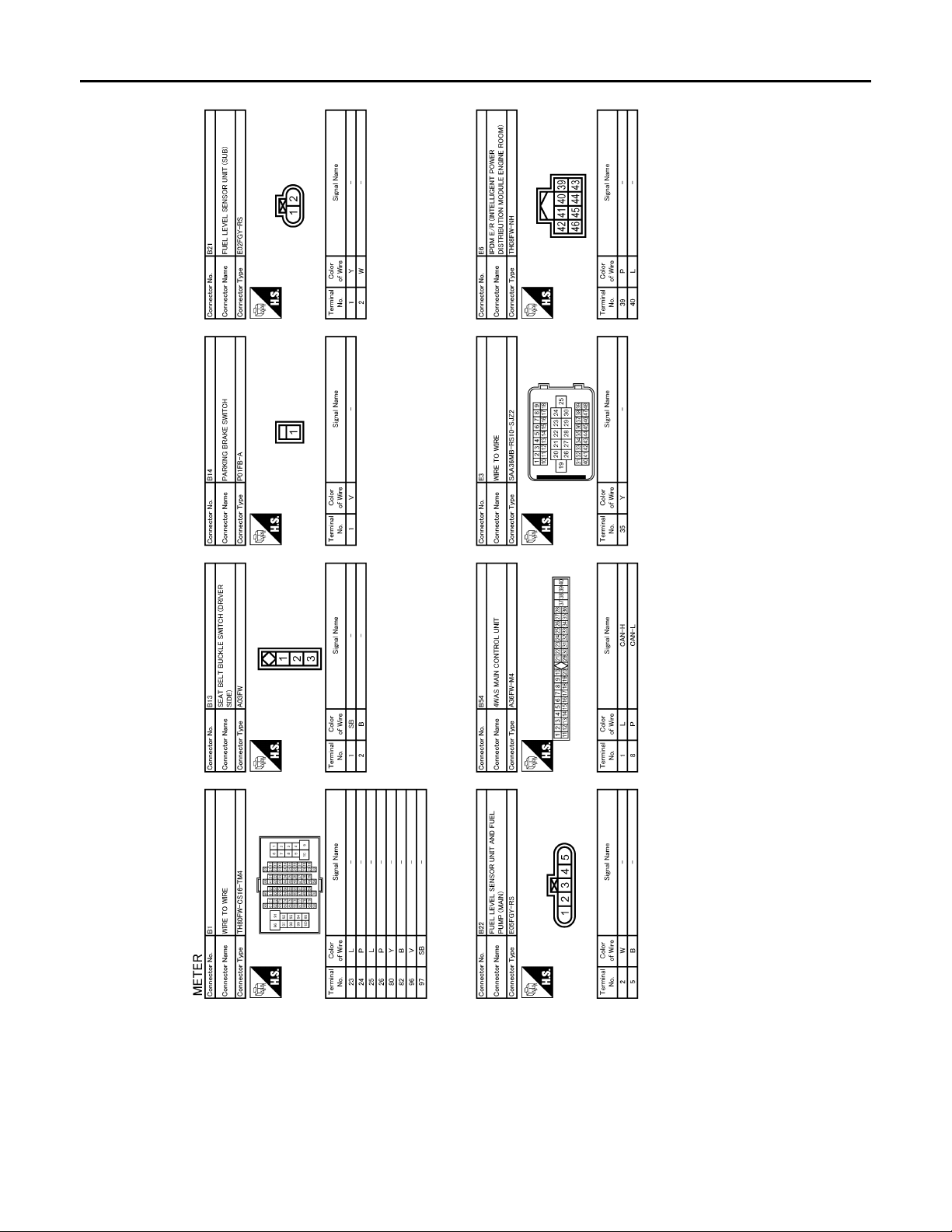
< ECU DIAGNOSIS >
B
2007 G35 Sedan
Revision: October 2006
COMBINATION METER
JCNWA0004G
INL-86
Page 87
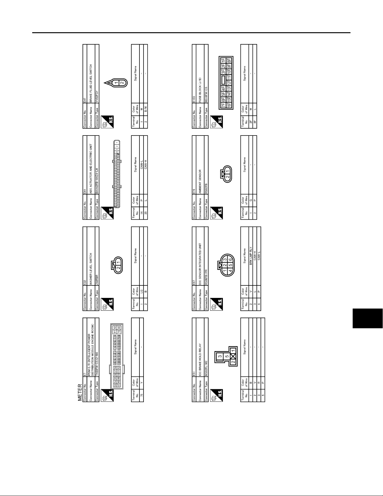
< ECU DIAGNOSIS >
B
2007 G35 Sedan
Revision: October 2006
COMBINATION METER
A
B
C
D
E
F
G
H
J
K
INL
M
N
O
I
JCNWA0005G
P
INL-87
Page 88
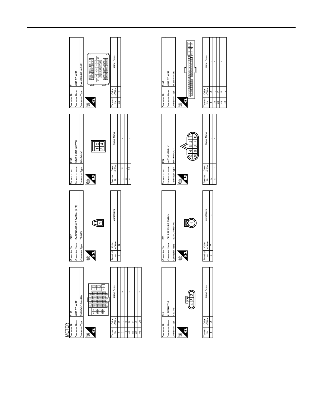
< ECU DIAGNOSIS >
B
2007 G35 Sedan
Revision: October 2006
COMBINATION METER
JCNWA0006G
INL-88
Page 89
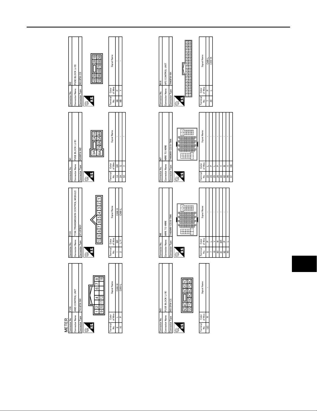
< ECU DIAGNOSIS >
B
2007 G35 Sedan
Revision: October 2006
COMBINATION METER
A
B
C
D
E
F
G
H
J
K
INL
M
N
O
I
JCNWA0007G
P
INL-89
Page 90
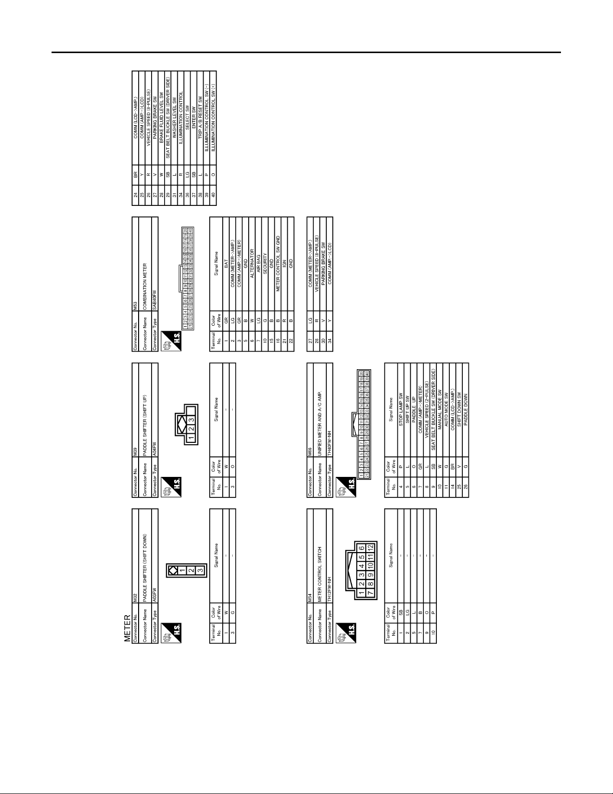
< ECU DIAGNOSIS >
B
2007 G35 Sedan
Revision: October 2006
COMBINATION METER
JCNWA0008G
INL-90
Page 91
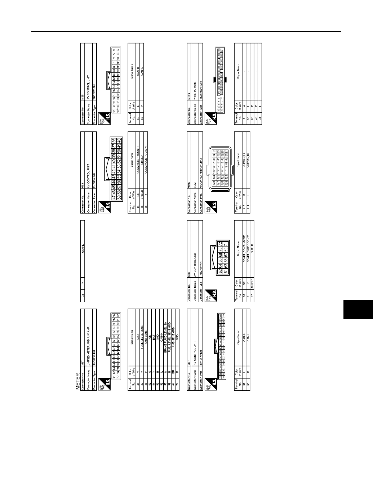
< ECU DIAGNOSIS >
B
2007 G35 Sedan
Revision: October 2006
COMBINATION METER
A
B
C
D
E
F
G
H
J
K
INL
M
N
O
I
JCNWA0009G
P
INL-91
Page 92
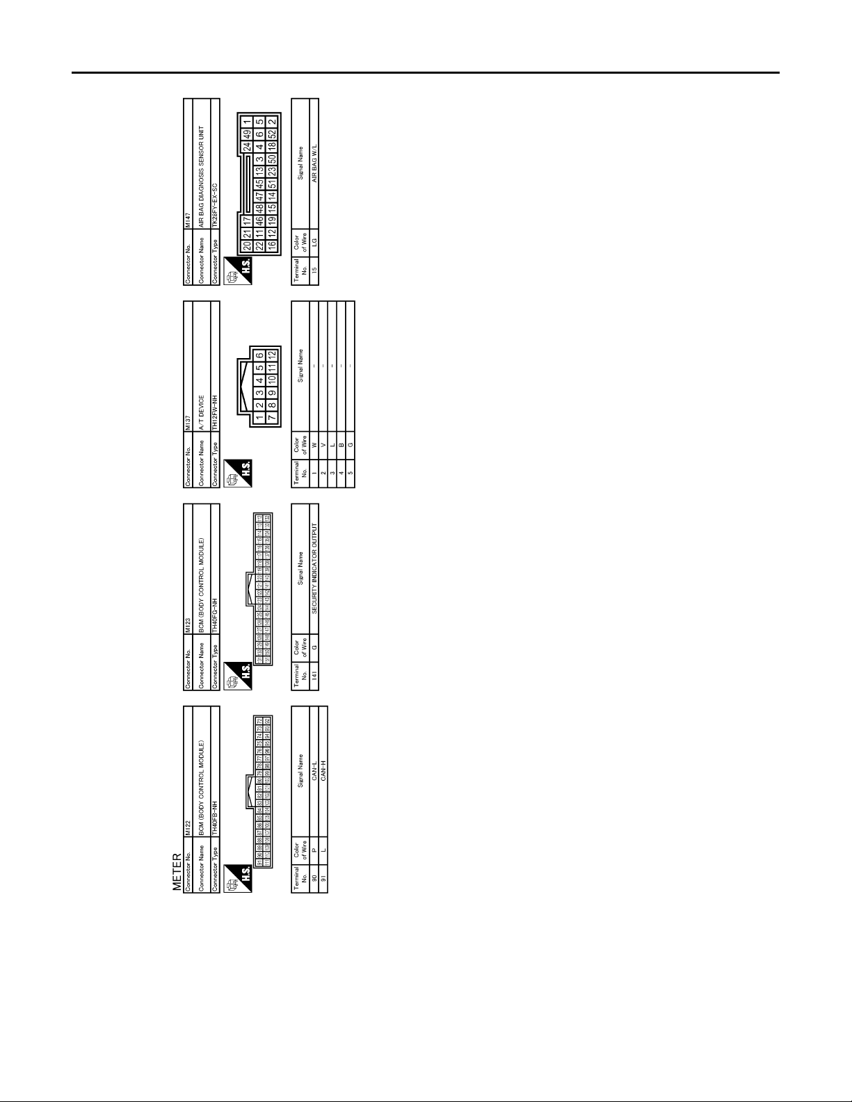
< ECU DIAGNOSIS >
B
2007 G35 Sedan
Revision: October 2006
COMBINATION METER
Fail Safe
FA IL SAFE
Combination meter performs fail-safe operation when unified meter and A/C amp. communication is malfunction.
Solution for communication error between the unified meter and A/C amp. and combination meter.
JCNWA0010G
INFOID:0000000000962606
INL-92
Page 93

< ECU DIAGNOSIS >
2007 G35 Sedan
Revision: October 2006
COMBINATION METER
Function Specifications
Speedometer
Tachometer
Fuel gauge
Water temperature gauge
Illumination control When suspending communication, change to nighttime mode.
Information display The display turns off by suspending communication.
Buzzer The buzzer turns off by suspending communication.
ABS warning lamp
VDC OFF indicator lamp
SLIP indicator lamp
Brake warning lamp
CRUISE warning lamp
BA warning lamp
High beam indicator
Turn signal indicator lamp
Warning lamp/indicator
lamp
Front fog indicator lamp
Oil pressure warning lamp
Malfunction indicator lamp
A/T CHECK warning lamp
AWD warning lamp
Low tire pressure warning lamp
Key warning lamp
AFS OFF indicator lamp
4WAS warning lamp
Master warning lamp
Reset to zero by suspending communication.
The lamp turns on by suspending communication.
The lamp turns off by suspending communication.
DTC Index INFOID:0000000000962607
A
B
C
D
E
F
G
H
I
J
K
Refer to MWI-97, "DTC Index".
INL
M
N
O
P
INL-93
Page 94

INTERIOR LIGHTING SYSTEM SYMPTOMS
2007 G35 Sedan
Revision: October 2006
< SYMPTOM DIAGNOSIS >
SYMPTOM DIAGNOSIS
INTERIOR LIGHTING SYSTEM SYMPTOMS
Symptom Table INFOID:0000000000962608
CAUTION:
Perform the self-diagnosis with CONSULT-III before the symptom diagnosis. Perform the trouble diagnosis if any DTC is detected.
Symptom Possible cause Inspection item
All the following lamps do not turn ON.
•Map lamp
•Personal lamp
• Trunk room lamp
•Step lamp
• Vanity mirror lamp
• Interior room lamp does not turn ON even
though the door is open.
(It turns ON when turning the interior room
lamp ON.)
• Interior room lamp does not turn OFF even
though the door is closed.
Interior room lamp timer does not activate.
(It turns ON/ OFF when the door opens/closes.)
Step lamps (driver side and passenger side) do
not turn ON.
(The map lamp and the personal lamp turn ON.)
Step lamps (driver side and passenger side) do
not turn OFF.
(The map lamp and the personal lamp turn OFF.)
• Trunk room lamp does not turn ON.
(The bulb is normal.)
• Trunk room lamp does not turn OFF.
Push-button ignition switch illumination does not
illuminate.
Interior room lamp battery saver does not activate.
• Harness between BCM and each
interior room lamp
•BCM
• Harness between BCM and each
door switch
• Harness between BCM and each
interior room lamp
•BCM
—
• Harness between BCM and each
step lamp
•BCM
• Harness between BCM and trunk
room lamp switch
• Harness between BCM and trunk
room lamp
•BCM
• Harness between BCM and pushbutton ignition switch
•BCM
—
Interior room lamp power supply circuit
Refer to INL-18
Door switch circuit
Refer to DLK-65
Interior room lamp control circuit
Refer to INL-20
Check the interior room lamp setting.
Refer to INL-13
Step lamp circuit
Refer to INL-22
Trunk room lamp switch circuit
Refer to DLK-84
Trunk room lamp circuit
Refer to INL-24
Push-button ignition switch illumination circuit
Refer to INL-24
Check the interior room lamp bat tery
saver setting.
Refer to INL-15
.
.
.
.
.
.
.
.
.
INL-94
Page 95

< PRECAUTION >
2007 G35 Sedan
Revision: October 2006
PRECAUTIONS
PRECAUTION
PRECAUTIONS
Supplemental Restraint System (SRS) "AIR BAG" and "SEAT BELT PRE-TENSIONER" INFOID:0000000000962609
The Supplemental Restraint System such as “AIR BAG” and “SEAT BELT PRE-TENSIONER”, used along
with a front seat belt, helps to reduce the risk or severity of injury to the driver and front passenger for certain
types of collision. This system includes seat belt switch inputs and dual stage front air bag modules. The SRS
system uses the seat belt switches to determine the front air bag deployment, and may only deploy one front
air bag, depending on the severity of a collision and whether the front occupants are belted or unbelted.
Information necessary to service the system safely is included in the SRS and SB section of this Service Manual.
WARNING:
• To avoid rendering the SRS inoperative, which could increase the risk of personal injury or death in
the event of a collision which would result in air bag inflation, all maintenance must be performed by
an authorized NISSAN/INFINITI dealer.
• Improper maintenance, including incorrect removal and installation of the SRS, can lead to personal
injury caused by unintentional activation of the system. For removal of Spiral Cable and Air Bag
Module, see the SRS section.
• Do not use electrical test equipment on any circuit related to the SRS unless instructed to in this
Service Manual. SRS wiring harnesses can be identified by yellow and/or orange harnesses or harness connectors.
A
B
C
D
E
F
G
H
J
K
INL
M
N
O
P
I
INL-95
Page 96
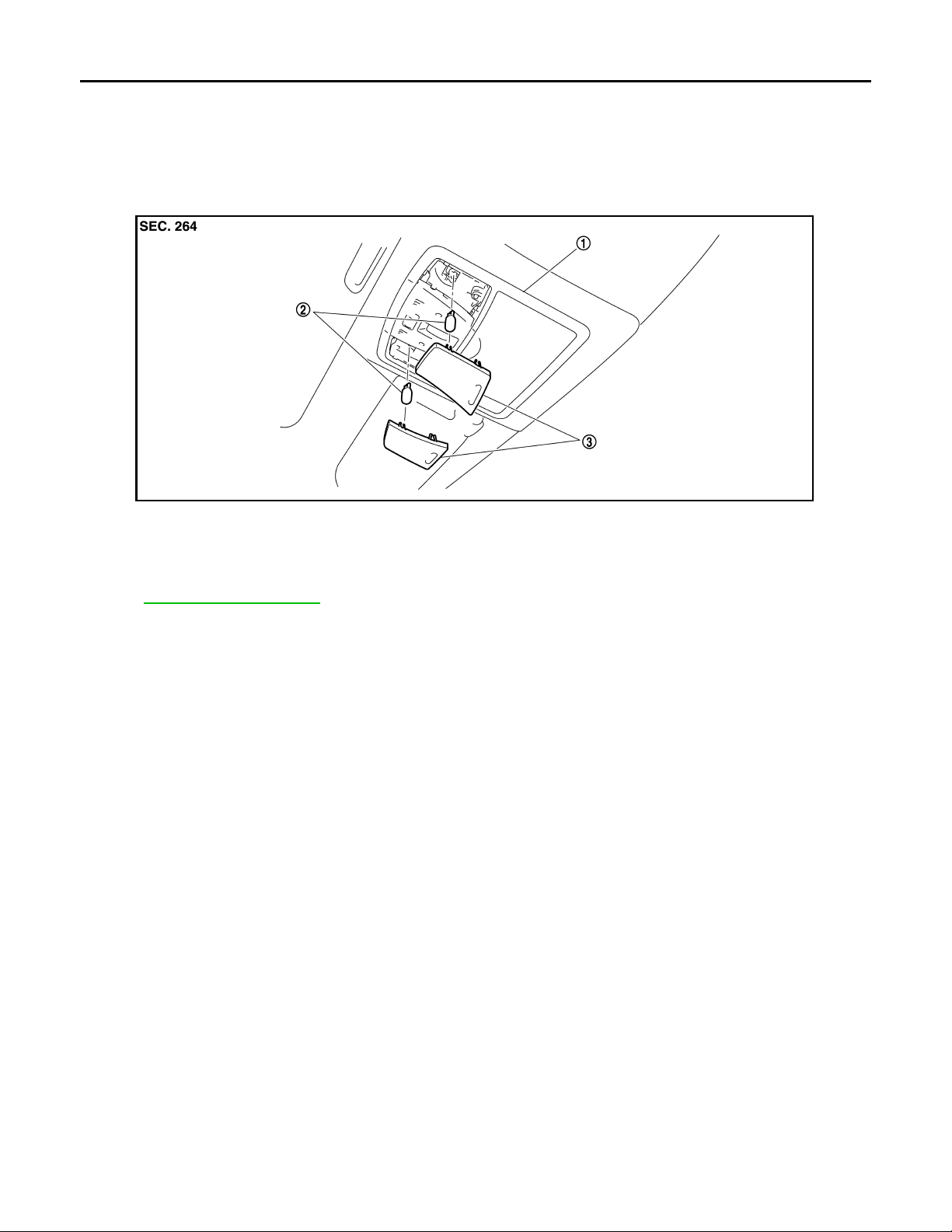
MAP LAMP
2007 G35 Sedan
Revision: October 2006
< ON-VEHICLE REPAIR >
ON-VEHICLE REPAIR
MAP LAMP
Exploded View INFOID:0000000000962610
JPLIA0059ZZ
1. Map lamp assembly 2. Bulb 3. Lens
Removal and Installation INFOID:0000000000962611
Refer to INT-22, "Exploded View" for the map lamp assembly installation/removal.
Replacement INFOID:0000000000962612
CAUTION:
Disconnect the battery negative terminal or the fuse.
MAP LAMP BULB
1. Insert any appropriate tool into the gap between the lens. Remove the lens.
2. Remove the bulb.
INL-96
Page 97
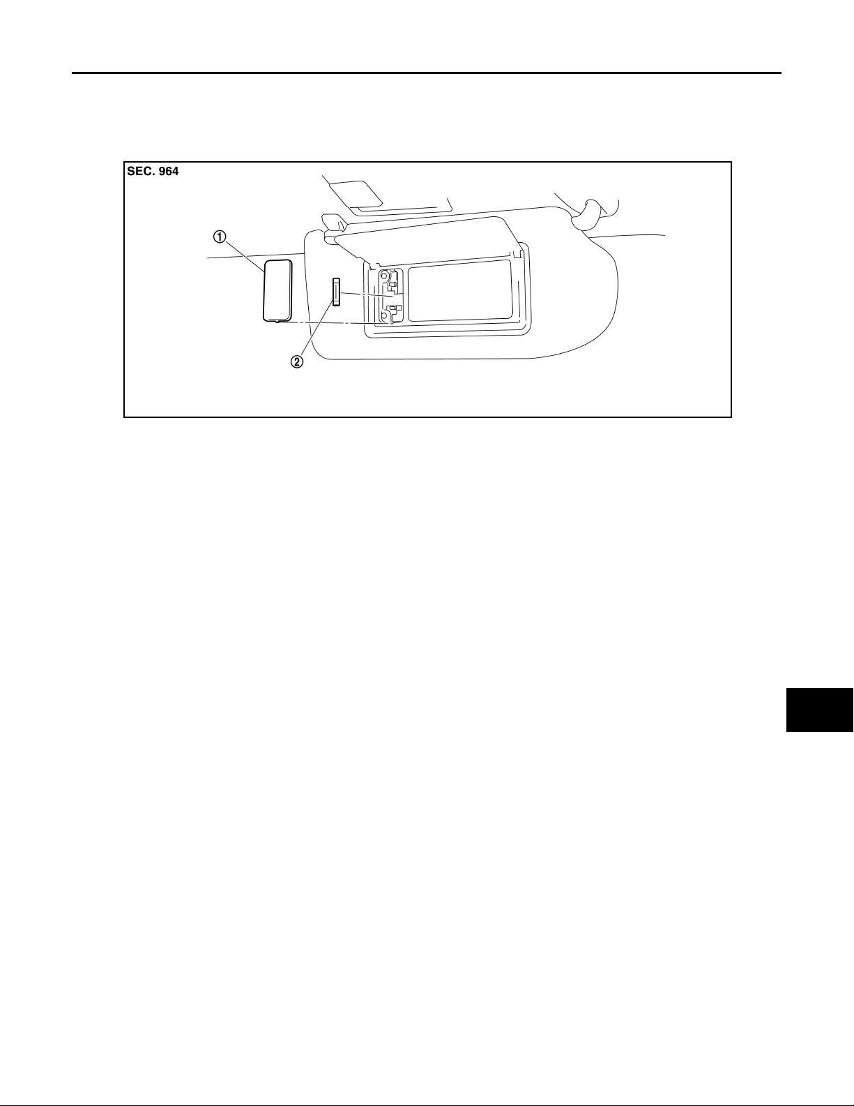
< ON-VEHICLE REPAIR >
2007 G35 Sedan
Revision: October 2006
VANITY MIRROR LAMP
VANITY MIRROR LAMP
Exploded View INFOID:0000000000962613
JPLIA0061ZZ
1. Lens 2. Bulb
Replacement INFOID:0000000000962614
CAUTION:
Disconnect the battery negative terminal or the fuse.
A
B
C
D
E
F
G
H
VANITY MIRROR LAMP BULB
1. Insert any appropriate tool into the gap between the lens. Remove the lens.
2. Remove the bulb.
I
J
K
INL
M
N
O
P
INL-97
Page 98
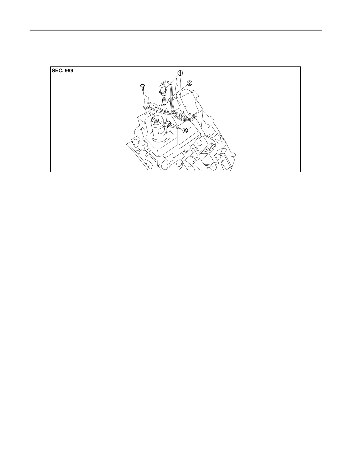
CIGARETTE LIGHTER ILLUMINATION
2007 G35 Sedan
Revision: October 2006
< ON-VEHICLE REPAIR >
CIGARETTE LIGHTER ILLUMINATION
Exploded View INFOID:0000000000962615
JPLIA0068ZZ
1. Bulb so ck et 2. Bulb
(Share with the ashtray illumination)
AHook
Replacement INFOID:0000000000962616
CAUTION:
Disconnect the battery negative terminal or the fuse.
CIGARETTE LIGHTER ILLMINATION BULB
1. Remove the console finisher. Refer to IP-22, "Exploded View".
2. Insert any appropriate tool into the gap of the bulb socket. Widen the hook and remove the bulb socket.
3. Remove the bulb.
INL-98
Page 99
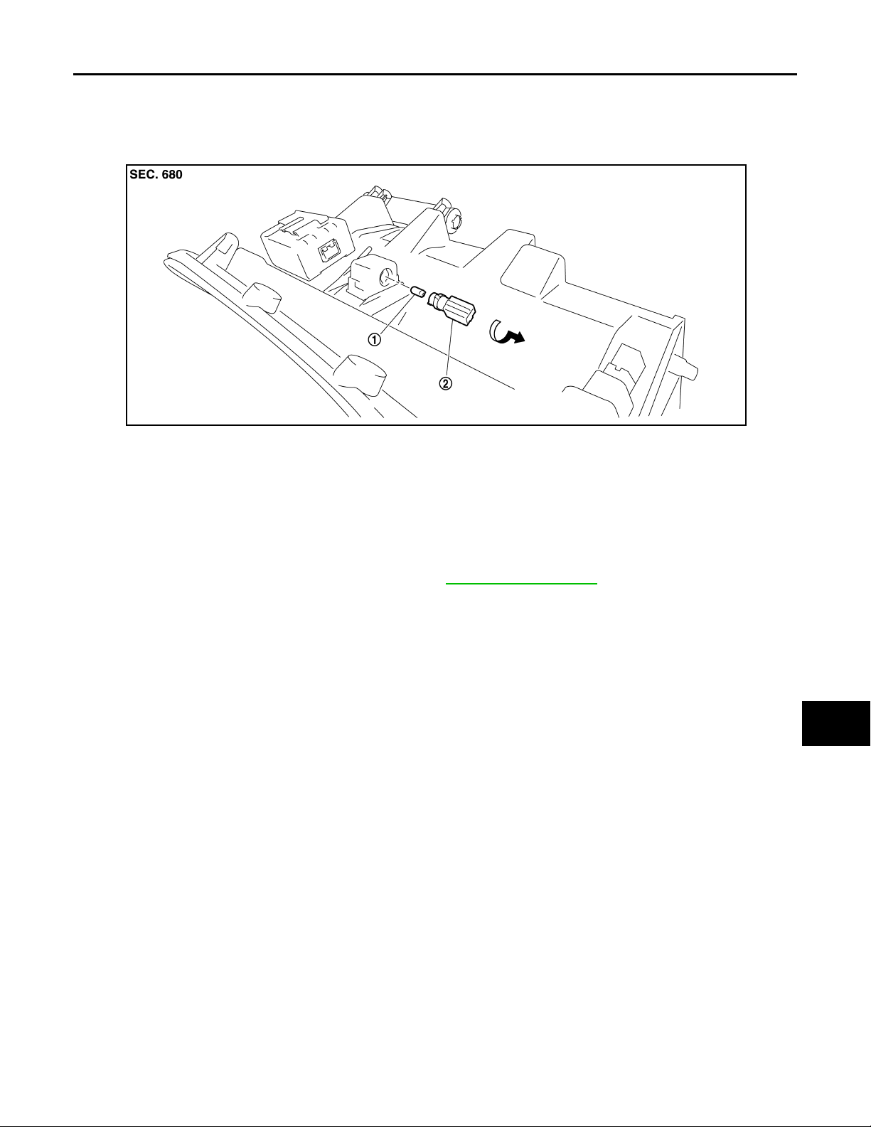
< ON-VEHICLE REPAIR >
2007 G35 Sedan
Revision: October 2006
GLOVE BOX LAMP
GLOVE BOX LAMP
Exploded View INFOID:0000000000962617
JPLIA0066ZZ
1. Bulb 2. Bulb socket
Replacement INFOID:0000000000962618
CAUTION:
Disconnect the battery negative terminal or the fuse.
A
B
C
D
E
F
G
H
GLOVE BOX LAMP BULB
1. Remove the instrument assist lower panel. Refer to IP-11, "Exploded View".
2. Rotate the bulb socket counterclockwise and unlock it.
3. Remove the bulb.
I
J
K
INL
M
N
O
P
INL-99
Page 100
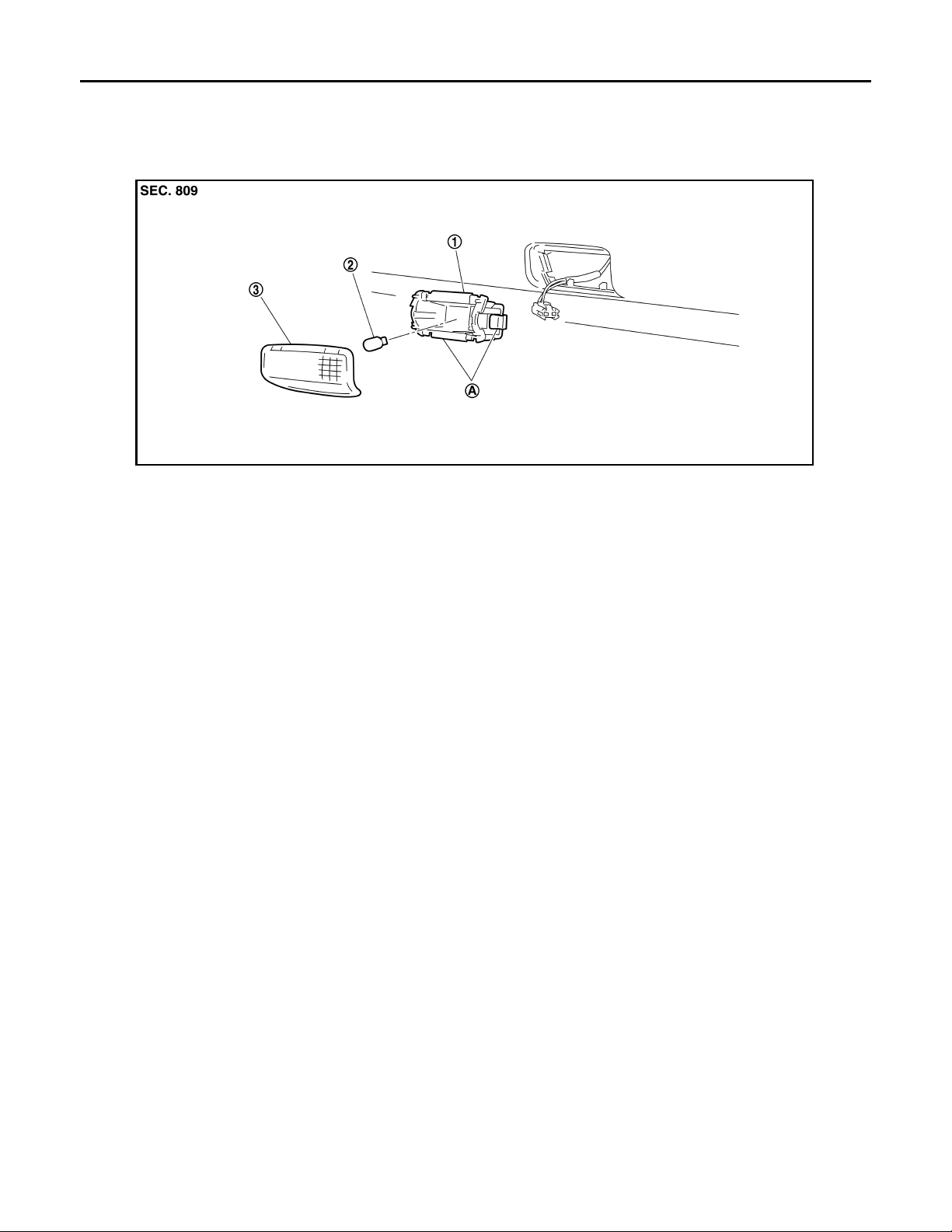
STEP LAMP
2007 G35 Sedan
Revision: October 2006
< ON-VEHICLE REPAIR >
STEP LAMP
Exploded View INFOID:0000000000962619
JPLIA0062ZZ
1. Step lamp case 2. Bulb 3. Lens
AMetal clip
Removal and Installation INFOID:0000000000962620
CAUTION:
Disconnect the battery negative terminal or the fuse.
REMOVAL
1. Insert any appropriate tool into the gap between the step lamp and the door trim. Remove the step lamp.
2. Disconnect the connector.
INSTALLATION
Install in the reverse order of removal.
Replacement INFOID:0000000000962621
CAUTION:
Disconnect the battery negative terminal or the fuse.
STEP LAMP BULB
1. Remove the step lamp.
2. Remove the lens.
3. Remove the bulb.
INL-100
 Loading...