

Page 1
The ILC6375 is a high efficiency step-down DC-DC controller using a PWM control scheme. The typical efficiency
can be as high as 85% to 90% at 10mA to 1 Amp load.
The ILC6375 drives an external switching transistor to
deliver up to 1 Amp of output current. The internal oscillator
operates at a fixed 100kHz frequency. Meanwhile, the
device is capable of 100% duty cycle thus allowing true low
drop-out operation to maximize battery life in portable
applications. Output voltage is trimmed to ±2.5% accuracy.
The device includes internal phase compensation and softstart circuitry. Available in a tiny SOT-89 package, the
ILC6375 requires an external PNP switching transisitor, an
inductor, a shottky diode and capacitors.
! Up to 1 Amp output current
! 85% to 90% efficiency at 0.5A to1A (V
IN
= 7V, V
OUT
= 5V)
! 85% efficiency at 10mA (V
IN
= 7V, V
OUT
= 5V)
! 100% Duty Cycle for ultra low drop-out
! 100kHz ±15% internal oscillator
! 10V(max) input voltage
! ±2.5% precision output
! Tiny SOT-89 package
! Cellular Phones
! Palmtop PCs and PDAs
! Portable instrumentation
! Digital cameras
! High efficiency 5V to 3.3V converter
PWM Controlled
BUFFER
V
DD
EXT
+
-
OSC
100kHz
V
OUT
PWM co mp
V
re f
Slow St art
V
IN
V
IN
SD
+
V
OUT
132
45
ILC6375
C
L
GND
L
Tr
R
B
C
IN
+
( 10V )
5V/1A
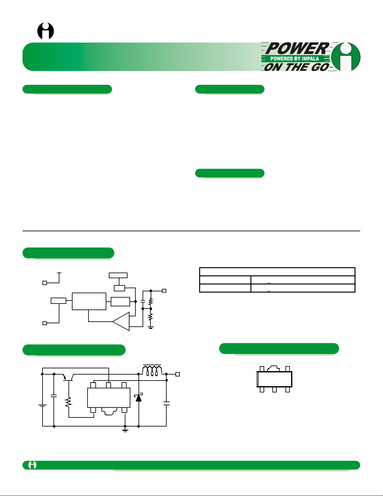
SOT -89-5
(TOP VIE W)
132
VINV
OUT
EXT
45
GND
N/C
ILC6375
Ordering Information*
ILC6375CP-33 3.3V+2.5% @100kHz external xtor
ILC6375CP-50 5.5V+2.5% @100kHz external xtor
* Standard product offering comes in tape & reel, quantity
1000 per reel, orientation right for SOT-89
ILC6375
1 Amp SOT-89 Step Down PWM Switcher Controller
Impala Linear Cor poration
Impala Linear Corporation
1
(408) 574-3939
www.impalalinear.com
June 1999
ILC6375 1.1
General Description
Features
Applications
Block Diagram
Typical Application
Pin Package Configuration
Page 2

Parameter Symbol Ratings Units
Input Voltage V
IN
12 V
Voltage on V
OUT
pin V
OUT
12 V
Voltage on pin EXT V
EXT
-0.3 to VIN + 0.3 V
Current on pin EXT I
EXT
+50 mA
Continuous Total Power Dissipation P
D
500 mW
Operating Ambient Temperature T
A
-30 to +80
ο
C
Storage Temper atures T
STG
-40 to+125
ο
C
Parameter
Symbol
Conditions
Min
Typ
Max
Units
Output Voltage
V
OUT
4.875
5.000
5.125
V
Input Voltage
VIN 10
V
Supply Current 1
I
DD
1
4.75V applied to V
OUT
with no
external components
25
42
µA
Supply Current 2
I
DD
2
5.5V applied to V
OUT
with no
external components
20
34
µA
EXT “High” ON Resistance
R
EXTH
5.5V applied to V
OUT
with no
external components, V
EXT
=4.6V
38
63
Ω
EXT “Low” ON Resistance
R
EXTL
4.75V applied to V
OUT
with no
external components, V
EXT
=0.4V
30
50
Ω
Oscillator Frequency
F
OSC
Measure Frequency at EXT pin
85
100
115
kHz
Maximum Duty Ratio
MAXDTY
Measure Duty Cycle at EXT pin
100
%
Efficiency
EFFI
90 %
Soft-Start Time
TSS
10 ms
V
OUT
= 5.0V F
OSC
= 100kHz TA= 25oC, unless otherwise specified, V
IN
= 6V, I
OUT
= 100mA, See test circuit, figure 1.
1 Amp SOT-89 Step Down PWM Switcher Controller
Impala Linear Corporation
2
(408) 574-3939
www.impalalinear.com
June 1999
ILC6375 1.1
Absolute Maximum Ratings (TA = 25οοC)
Electrical Characteristics ILC6375CP-50
Page 3

Parameter
Symbol
Conditions
Min
Typ
Max
Units
Output Voltage
V
OUT
3.218
3.300
3.383
V
Input Voltage
VIN 10
V
Supply Current 1
I
DD
1
3V applied to V
OUT
with no
external components
20
33
µA
Supply Current 2
I
DD
2
3.6V applied to V
OUT
with no
external components
16
27
µA
EXT “High” ON Resistance
R
EXTH
3.6V applied to V
OUT
with no
external components,V
EXT
= 3.6V
57
95
Ω
EXT “Low” ON Resistance
R
EXTL
3V applied to V
OUT
with no
external components, V
EXT
= 0.4V
46
76
Ω
Oscillator Frequency
F
OSC
Measure Frequency at EXT pin
85
100
115
kHz
Maximum Duty Ratio
MAXDTY
Measure Duty Cycle at EXT pin
100
%
Efficiency
EFFI
90 %
Soft Start Time
TSS
10 ms
V
OUT
= 3.3V F
OSC
= 100kHz TA= 25oC,unless otherwise specified, V
IN
= 4V, I
OUT
= 55mA, See test circuit, figure 1.
V
IN
SD
+
V
OU T
132
45
ILC6375
C
L
GND
L
Tr
R
B
C
IN
+
( 5V )
( 5V to 10V )
Figure 1: ILC6375 Typical Application
L: 100mH (SUMIDA CD-54)
SD: Shottkey Diode (MATSUSHITA MA735
C
IN
: 10mF/16V Tantalum Capacitor (NICHICON F93)
C
L
: 47mF/10V Tantalum Capacitor (NICHICON F93)
Tr: PNP Transistor (TOSHIBA 2SA1213)
R
B
1kΩ
1 Amp SOT-89 Step Down PWM Switcher Controller
Impala Linear Corporation
3
(408) 574-3939
www.impalalinear.com
June 1999
ILC6375 1.1
Electrical Characteristics ILC6375CP-33
Applications Circuits
Page 4

OUTPUT CURRENT I
OUT
(mA)
0
OUTPUT VOLTAGE V
OUT
(V)
110
8.0V
5.0
4.6
4.4
4. 2
100 1000
10.0V
V
IN
=5.0V
7.0V
5.2
4.8
OUTPUT CURRENT I
OUT
(mA)
0
OUTPUT VOLTAGE V
OU T
(V)
110
4.8
4.4
4.2
4.0
100 1000
VIN=5.0V
5.1V
5.2
4.6
4.0
5.0
VIN=
ILC6 37 5C P- 50
Output Voltage vs Output Current
Output Voltage vs Output Current
ILC6375CP-50
OUTPUT CURRENT I
OUT
(mA)
0
EFFICIENCY ( % )
110
80
60
40
20
100 1000
10 0
0
Vin= 5.5 V
Vin = 10. 0V
Vin =7 . 0V
Efficienc y vs Output Curre nt
ILC6375CP- 50
OUTPUT CURRENT I
OUT
(mA)
0
RIPPLE (mVP-P)
110
80
60
40
20
100 1000
10 0
0
Vin=5.5V
Vin =7.0V
Vin=8.0V
Output Ripple Voltage vs Output Current
ILC6375CP-50
OUTPU T CURRENT I
OUT
(mA )
0
EFFICIENCY ( % )
110
80
60
40
20
10 0 10 00
10 0
0
Vin = 7.0V
Vin =4V
Vin =5.0V
Efficiency vs Output Current
ILC637 5CP-33
OUTPU T CURRENT I
OUT
(mA )
0
RIPPLE (mVP-P)
110
80
60
40
20
1 00 1 000
10 0
0
Vin=4V
Vin=5.0V
Vin=7.0V
Output Ripple Voltage vs Out put Curre nt
ILC6375CP- 33
L = 100kHz CL = 47µF3.3V F
OSC TA
= 25oC, unless otherwise specified, V
IN
= 4V, I
OUT
= 55mA, See test circuit, figure 1.
1 Amp SOT-89 Step Down PWM Switcher Controller
Impala Linear Corporation
4
(408) 574-3939
www.impalalinear.com
June 1999
ILC6375 1.1
Electrical Characteristics ILC6375CP-33
 Loading...