

Semiconductor
IH5140 thru IH5145
April 1999
OBSOLETE PRODUCT
High-Level CMOS Analog Switches
POSSIBLE SUBSTITUTE PRODUCT
Features
• Super Fast Break-Before-Make Switching
• SPST Switches (Typ)
-t
. . . . . . . . . . . . . . . . . . . . . . . . . . . . . . . . . . . . 80ns
ON
. . . . . . . . . . . . . . . . . . . . . . . . . . . . . . . . . . . 50ns
-t
OFF
• Power Supply Currents . . . . . . . . . . . . . . . . . . . . <1µA
• OFF Leakages at 25
• Non-Latching with Supply Turn-Off
• Single Monolithic CMOS Chip
• Plug-In Replacements for IH5040 Family and Part of
the DG180 Family to Upgrade Speed and Leakage
• Toggle Rate. . . . . . . . . . . . . . . . . . . . . . . . . . . . . . >1MHz
• Switches Signals with ±15V Supplies. . . . . . . . . . . . >20V
• TTL, CMOS Direct Compatibility
• Internal Diode in Series with V+ for Fault Protection
IH5140, IH5141: DG401
IH5142: HI-5042, DG403, HI-5043
IH5143: DG403, HI-5043, HI-0390
IH5144, IH5145: HI-5049, HI-5045
NOTE: Pinout and pin count of single devices
allow dual devices to be pin compatible
replacements.
o
C (Typ). . . . . . . . . . . . . . . <100pA
Description
The IH5140 Family of CMOS switches utilizes Harris’ latchfree junction isolated processing to build the fastest switches
currently available . These switches can be toggled at a rate of
greater than 1MHz with fast t
faster t
make switching. This family of switches combines the speed
of the hybrid FET DG180 family with the reliability and low
power consumption of a monolithic CMOS construction.
Very low quiescent power is dissipated in either the ON or
the OFF state of the switch. Maximum power supply current
is 10µA (at 25
rents are in the 10nA which makes these devices ideal for
portable equipment and military applications.
The IH5140 Family is completely compatible with TTL (5V)
logic, TTL open collector logic and CMOS logic. It is pin
P-P
compatible with Harris’ IH5040 family and part of the
DG180/DG190 family as shown in the s witching state diagrams .
times (50ns typical), guaranteeing break before
OFF
o
C) from any supply and typical quiescent cur-
Part Number Information
PART NUMBER FUNCTION TEMP. RANGE (oC) PACKAGE PKG. NO.
IH5140MJE SPST -55 to 125 16 Ld CerDIP
IH5140CJE SPST 0 to 70 16 Ld CERDIP
IH5140CPE SPST 0 to 70 16 Ld PDIP
IH5141MJE Dual SPST -55 to 125 16 Ld CerDIP
IH5141CJE Dual SPST 0 to 70 16 Ld CERDIP
IH5141CPE Dual SPST 0 to 70 16 Ld PDIP
IH5142MJE SPDT -55 to 125 16 Ld CerDIP
IH5142CJE SPDT 0 to 70 16 Ld CERDIP
IH5142CPE SPDT 0 to 70 16 Ld PDIP
IH5143MJE Dual SPDT -55 to 125 16 Ld CERDIP
IH5143CJE Dual SPDT 0 to 70 16 Ld CerDIP
IH5143CPE Dual SPDT 0 to 70 16 Ld PDIP
IH5144MJE DPST -55 to 125 16 Ld CERDIP
IH5144CJE DPST 0 to 70 16 Ld CERDIP
IH5144CPE DPST 0 to 70 16 Ld PDIP
IH5145MJE Dual DPST -55 to 125 16 Ld CerDIP
IH5145CJE Dual DPST 0 to 70 16 Ld CerDIP
IH5145CPE Dual DPST 0 to 70 16 Ld PDIP
IH5140MJE/883B SPST -55 to 125 16 Ld CERDIP
IH5141MJE/883B Dual SPST -55 to 125 16 Ld CERDIP
IH5142MJE/883B SPDT -55 to 125 16 Ld CERDIP
IH5143MJE/883B Dual SPDT -55 to 125 16 Ld CERDIP
IH5144MJE/883B DPST -55 to 125 16 Ld CERDIP
IH5145MJE/883B Dual DPST -55 to 125 16 Ld CERDIP
NOTE:
1. For MIL-STD-883 compliant parts, request the /883 datasheet on the above products.
times (80ns typical) and
ON
CAUTION: These devices are sensitive to electrostatic discharge. Users should follow proper IC Handling Procedures.
Copyright
© Harris Corporation 1999
13-1
File Number 3132.2
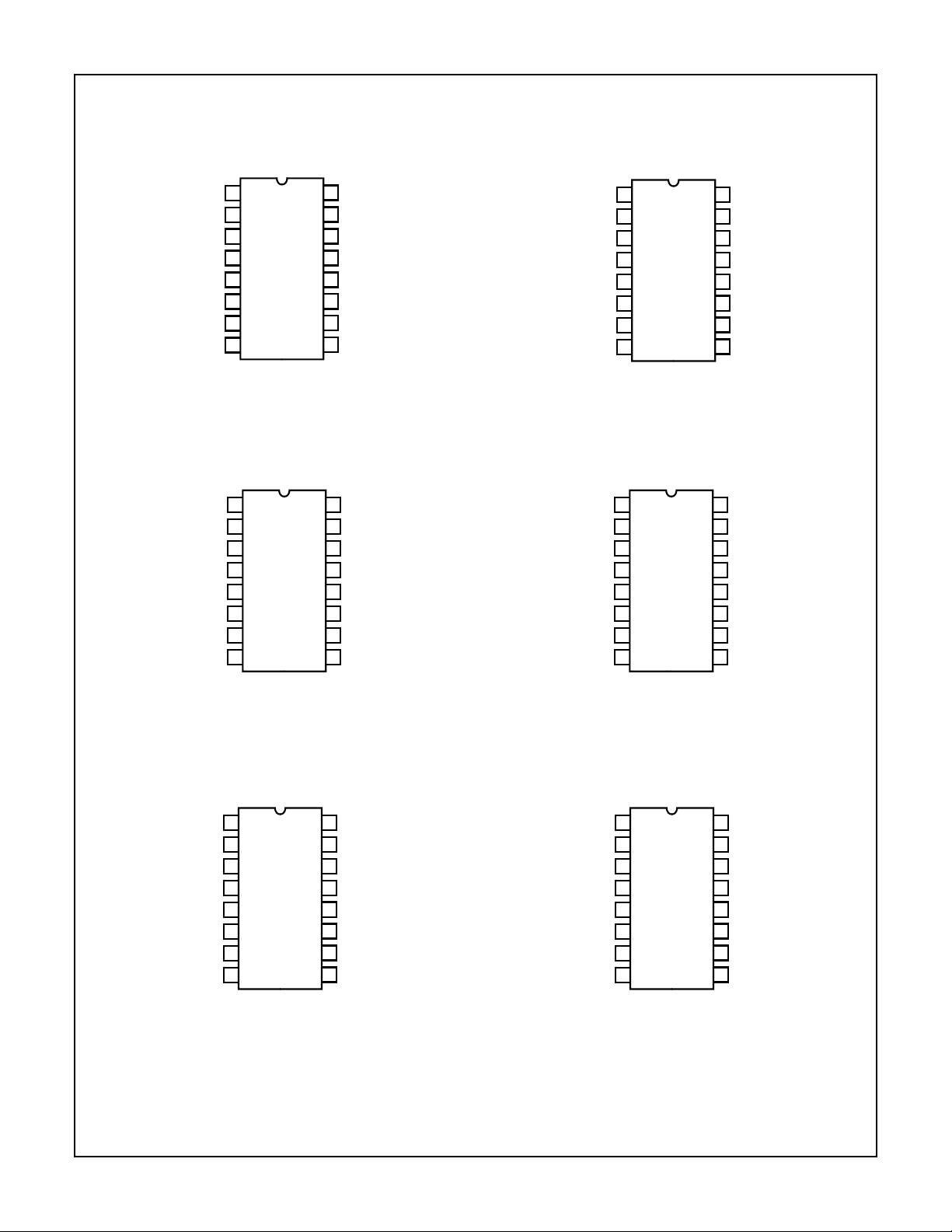
Pinouts
(PDIP, CERDIP)
TOP VIEW
1
D
2
NC
3
NC
4
NC
5
NC
6
NC
7
NC
8
NC
IH5140
IH5140 thru IH5145
IH5141
(PDIP, CERDIP)
TOP VIEW
16
S
15
IN
14
V-
13
GND
12
V
L
11
V+
10
NC
9
NC
D1
NC
NC
NC
NC
NC
NC
D
S
1
2
3
4
5
6
7
8
2
16
1
IN
15
1
V-
14
GND
13
V
12
L
V+
11
IN
10
2
S
9
2
(PDIP, CERDIP)
D
1
1
NC
2
D
3
2
S
4
2
NC
5
NC
6
NC
7
NC
8
(PDIP, CERDIP)
1
D
1
2
NC
3
D
2
4
S
2
5
NC
6
NC
7
NC
8
NC
IH5142
TOP VIEW
IH5144
TOP VIEW
IH5143
(PDIP, CERDIP)
TOP VIEW
16
S
1
15
IN
14
V-
13
GND
12
V
L
11
V+
10
NC
9
NC
D
NC
D
S
S
D
NC
D
16
1
1
2
3
3
4
3
5
4
6
4
7
8
2
S
1
15
IN
1
14
V-
13
GND
12
V
L
11
V+
10
IN
2
9
S
2
IH5145
(PDIP, CERDIP)
TOP VIEW
S
16
1
15
IN
14
V-
13
GND
12
V
L
11
V+
10
NC
9
NC
D
NC
D
S
S
D
NC
D
1
1
2
3
3
4
3
5
4
6
4
7
8
2
16
S
1
15
IN
1
14
V-
13
GND
12
V
L
11
V+
10
IN
2
9
S
2
13-2
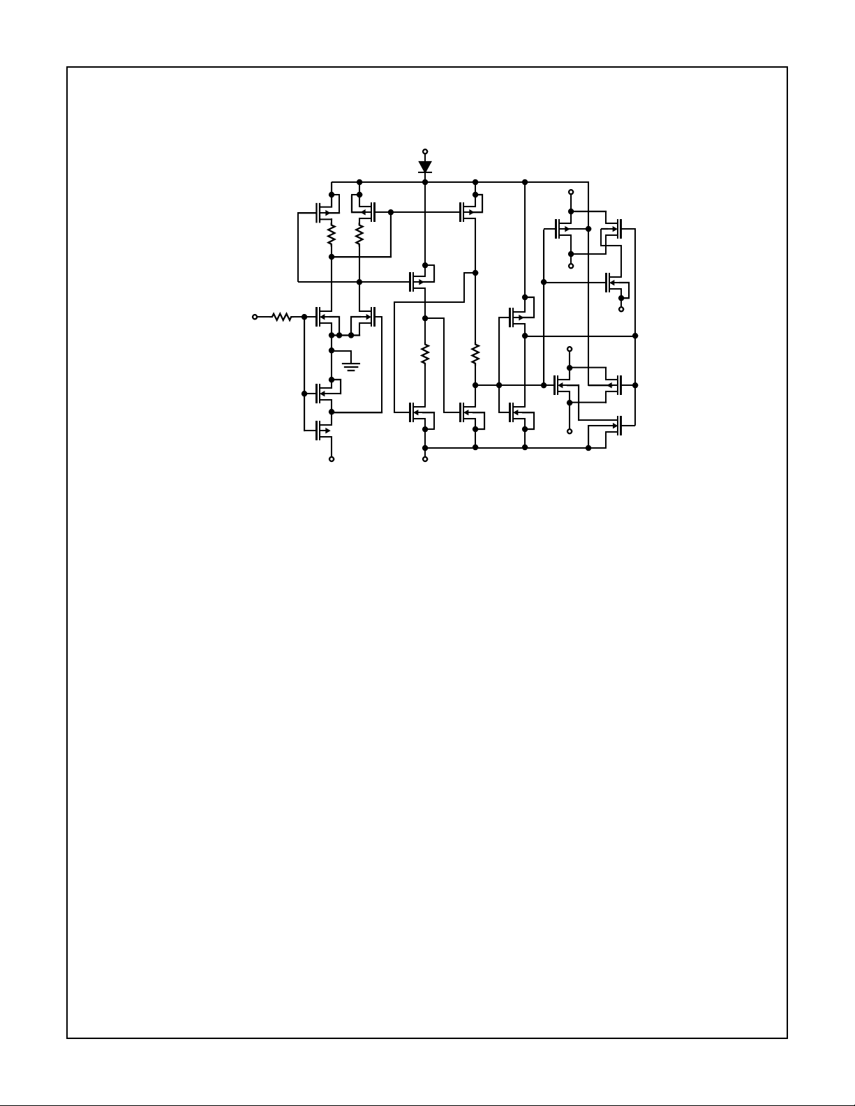
Functional Block Diagram
IH5140 thru IH5145
TYPICAL DRIVER/GATE - IH5142
V+
T
INPUT
Q3 Q7 Q5
10kΩ
100Ω
2
L
Q1 Q8
Q9
Q10
5kΩ
Q2
Q12
5kΩ 3kΩ
Q4 Q6 Q11
V+
V
L
V-
S1
Q16Q18
D1
S2
Q13 Q15
D2
Q17
Q14
V-
13-3
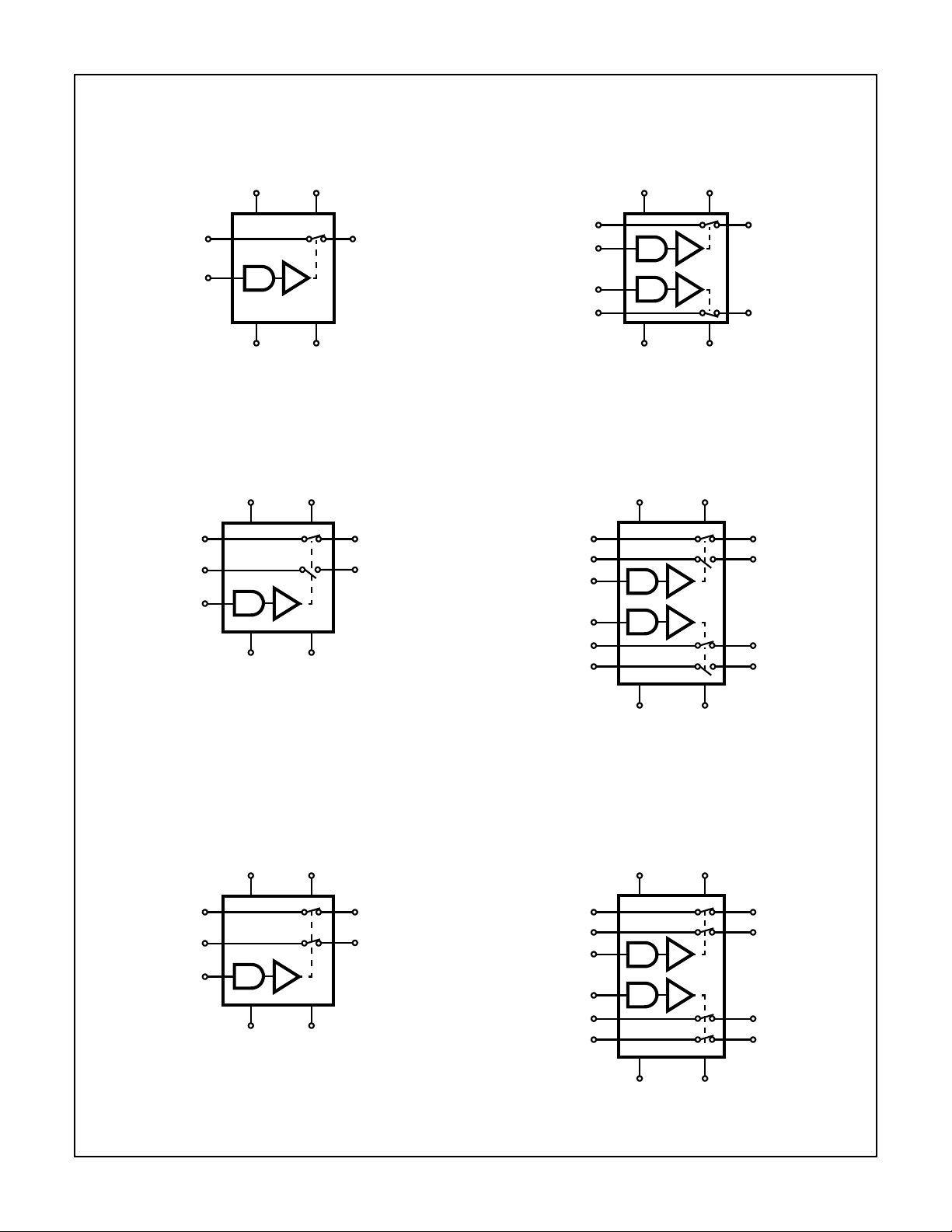
Switching State Diagrams
DIP (JE, PE)
SPST IH5140
IH5140 thru IH5145
DIP (JE, PE)
DUAL SPST IH5141
V
L
12 11
16
S
V+
V
L
12 11
16
1
D
S
1
15
IN
1
V+
1
D
1
15
IN
13 14
V-GND
DIP (JE, PE)
SPDT IH5142
V
L
12 11
16
S
1
4
S
2
15
IN
13 14
V+
1
D
1
3
D
2
V-GND
10
IN
2
9
S
2
8
D
2
13 14
V-GND
DIP (JE, PE)
DUAL SPDT IH5143
V
L
12 11
16
S
1
43
S
3
15
IN
1
10
IN
2
9
S
2
56
S
4
V+
1
D
1
D
3
8
D
2
D
4
13 14
V-GND
DIP (JE, PE)
DPST IH5144
V
L
12 11
16
S
1
4
S
2
15
IN
13 14
V+
1
D
1
3
D
2
V-GND
S
1
S
3
IN
1
IN
2
S
2
S
4
DIP (JE, PE)
DUAL DPST IH5145
V
L
12 11
16
43
15
10
9
56
V+
1
D
1
D
3
8
D
2
D
4
13 14
V-GND
13-4

IH5140 thru IH5145
Absolute Maximum Ratings Thermal Information
V+ to V-. . . . . . . . . . . . . . . . . . . . . . . . . . . . . . . . . . . . . . . . . . . <36V
V+ to VD. . . . . . . . . . . . . . . . . . . . . . . . . . . . . . . . . . . . . . . . . . <30V
VD to V- . . . . . . . . . . . . . . . . . . . . . . . . . . . . . . . . . . . . . . . . . . <30V
VD to VS. . . . . . . . . . . . . . . . . . . . . . . . . . . . . . . . . . . . . . . . . <±22V
VL to V-. . . . . . . . . . . . . . . . . . . . . . . . . . . . . . . . . . . . . . . . . . . <33V
VL to VIN. . . . . . . . . . . . . . . . . . . . . . . . . . . . . . . . . . . . . . . . . . <30V
VL to GND . . . . . . . . . . . . . . . . . . . . . . . . . . . . . . . . . . . . . . . . <20V
VIN to GND. . . . . . . . . . . . . . . . . . . . . . . . . . . . . . . . . . . . . . . . <20V
Current (Any Terminal) . . . . . . . . . . . . . . . . . . . . . . . . . . . . . . .30mA
Operating Conditions
Temperature Ranges
Military . . . . . . . . . . . . . . . . . . . . . . . . . . . . . . . . . -55oC to 125oC
Commercial. . . . . . . . . . . . . . . . . . . . . . . . . . . . . . . . .0oC to 70oC
CAUTION: Stresses above those listed in “Absolute Maximum Ratings” may cause permanent damage to the device. This is a stress only rating and operation
of the device at these or any other conditions above those indicated in the operational sections of this specification is not implied.
Thermal Resistance (Typical) θJA (oC/W) θJC (oC/W)
CERDIP Package . . . . . . . . . . . . . . . . 80 24
PDIP Package. . . . . . . . . . . . . . . . . . . 100 N/A
Maximum Junction Temperature
CERDIP Package . . . . . . . . . . . . . . . . . . . . . . . . . . . . . . . . 175oC
PDIP Package. . . . . . . . . . . . . . . . . . . . . . . . . . . . . . . . . . . 150oC
Maximum Storage Temperature Range . . . . . . . . . -65oC to 150oC
Maximum Lead Temperature (Soldering 10s). . . . . . . . . . . . . 300oC
Electrical Specifications 25
o
C, V+ = +15V, V- = -15V, VL = +5V
MILITARY COMMERCIAL
PER CHANNEL PARAMETER TEST CONDITIONS
UNITS-55oC25oC 125oC0oC25oC70oC
LOGIC INPUT
Input Logic Current, I
Input Logic Current, I
INH
INL
VIN = 2.4V, Note 1 ±1 ±110−±10 10 µA
VIN = 0.8V, Note 1 ±1 ±110−±10 10 µA
SWITCH
Drain Source On Resistance,
r
DS(ON)
Channel to Channel r
∆r
DS(ON)
DS(ON)
Match,
Minimum Analog Signal Handling
Capability, V
ANALOG
Switch OFF Leakage Current,
I
D(OFF)+IS(OFF)
Switch On Leakage Current,
I
D(ON)+IS(ON)
Minimum Channel to Channel Cross
Coupling Rejection Ratio, CCRR
IS = -10mA,
V
ANALOG
= -10V to +10V
50 50 75 75 75 100 Ω
- 25 (Typ) - - 30 (Typ) - Ω
- ±11
(Typ)
--±10
(Typ)
-V
VD = +10V, VS = -10V - ±0.5 100 - ±5 100 nA
VD = -10V, VS = +10V - ±0.5 100 - ±5 100 nA
VD = VS = -10V to +10V - ±1 200 - ±2 200 nA
One Channel Off; Any Other
- 54 (Typ) - - 50 (Typ) - dB
Channel Switches, See
Performance Characteristics
Switch “ON” Time, t
Switch “OFF” Time, t
Charge Injection, Q
ON
OFF
(INJ)
See Switching Time Specifications and Timing Diagrams
See Switching Time Specifications and Timing Diagrams
See Performance
- 10 (Typ) - - 15 (Typ) - pC
Characteristics
Minimum Off Isolation Rejection
Ratio, OIRR
f = 1MHz, RL = 100Ω,
CL≤ 5pF, See Performance
- 54 (Typ) - - 50 (Typ) - dB
Characteristics
SUPPLY
+ Power Supply Quiescent Current, I+ V+ = +15V, V- = -15V,
- Power Supply Quiescent Current, I- 1.0 1.0 10 10 10 100 µA
+5V Supply Quiescent Current, I
VL = +5V, See Performance
Characteristics
L
Ground Supply Quiescent Current,
I
GND
1.0 1.0 10 10 10 100 µA
1.0 1.0 10 10 10 100 µA
1.0 1.0 10 10 10 100 µA
NOTES:
1. Some channels are turned on by high (1) logic inputs and other channels are turned on by low (0) inputs; however 0.8V to 2.4V describes
the minimum range for switching properly. Refer to logic diagrams to find logical v alue of logic input required to produce ON or OFF state.
2. Typical values are for design aid only, not guaranteed and not subject to production testing.
13-5

IH5140 thru IH5145
Switching Time Specifications t
PART NUMBER SPECIFICATIONS
IH5140, IH5141 Switch “ON” Time, t
Switch “OFF” Time, t
Break-Before-Make,
tON - t
OFF
Switch “ON” Time, t
Switch “OFF” Time, t
IH5142, IH5143 Switch “ON” Time, t
Switch “OFF” Time, t
Break-Before-Make,
tON - t
OFF
Switch “ON” Time, t
Switch “OFF” Time, t
Switch “ON” Time, t
Switch “OFF” Time, t
Break-Before-Make,
tON - t
OFF
Switch “ON” Time, t
Switch “OFF” Time, t
Break-Before-Make,
tON - t
OFF
IH5144, IH5145 Switch “ON” Time, t
Switch “OFF” Time, t
Break-Before-Make,
tON - t
OFF
Switch “ON” Time, t
Switch “OFF” Time, t
ON
ON
ON
ON
ON
ON
ON
ON
OFF
OFF
OFF
OFF
OFF
OFF
OFF
OFF
, t
ON
are Maximum Specifications and tON - t
OFF
TEST
MILITARY COMMERCIAL
CONDITIONS
Figure 8, Note 2 - 100 - - 150 - ns
- 75 - - 125 - ns
-10--5-ns
Figure 7 - 150 - - 175 - ns
- 125 - - 150 - ns
Figure 8, Note 2 - 175 - - 250 - ns
- 125 - - 150 - ns
-10--5-ns
Figure 7 - 200 - - 300 - ns
- 125 - - 150 - ns
Figure 2, Note 2 - 175 - - 250 - ns
- 125 - - 150 - ns
-10--5-ns
Figure 3, Note 2 - 200 - - 300 - ns
- 125 - - 150 - ns
-10--5-ns
Figure 8, Note 2 - 175 - - 250 - ns
- 125 - - 150 - ns
-10--5-ns
Figure 7 - 200 - - 300 - ns
- 125 - - 150 - ns
NOTES:
1. Switching times are measured at 90% points.
2. Typical values are for design aid only, not guaranteed and not subject to production testing.
is Minimum Specification
OFF
UNITS-55oC25oC 125oC0oC25oC70oC
13-6

Typical Performance Curves
IH5140 thru IH5145
90
80
70
60
(Ω)
50
DS(ON)
r
40
30
20
+10
FIGURE 1. r
-120
-100
(dB)
-80
ANALOG
-60
/V
OUT
V
-40
-20
100
IH5141 DATA
90
80
60
(Ω)
50
DS(ON)
125oC
25oC
-55oC
+8 +6 +4 +2 0 -2 -4 -6 -8 -10
ANALOG SIGNAL VOLTAGE (V)
vs TEMPERA TURE A T±15V, +5V SUPPLIES FIGURE 2. r
DS(ON)
r
40
30
20
TA = 25oC IH5141 DATA
±5V, +5V SUPPLIES
±10V, +5V SUPPLIES
±15V, +5V SUPPLIES
+10 +8 +6 +4 +2 0 -2 -4 -6 -8 -10
ANALOG SIGNAL VOLTAGE (V)
vs POWER SUPPLIES
DS(ON)
COAX TO SCOPE
V
OUT
51Ω
V
AT FREQUENCY
1
2
3
4
5
6
7
8
16
15
14
-15V
13
12
+5V
11
+15V
10
9
ANALOG
51Ω
- 10V
P-P
0
100 1K 10K 100K 1M 10M
FREQUENCY (Hz)
FIGURE 3A. FIGURE 3B.
FIGURE 3. “OFF” ISOLATION vs FREQUENCY
2.8
2.6
2.4
2.2
2.0
1.8
I+ SUPPLY
1.6
1.4
I (mA)
1.2
1.0
0.8
0.6
I
0.4
GND
0.2
0
1 10 100 1000
I- SUPPLY
IL < 0.05mA FROM 1µs to DC
τ - PERIOD OF PULSE REPETITION RATE (µs)
FIGURE 4A. FIGURE 4B.
FIGURE 4. POWER SUPPLY CURRENTS vs LOGIC STROBE RATE
C = 1µF
SOCKET ON COPPER GROUND PLANE JIG
1
2
3
4
5
6
7
8
16
15
14
-15V
13
12
+5V
+15V
11
10
+10V
9
τ
ρ
100Ω
+3V
0V
ρ = 400ns
13-7

IH5140 thru IH5145
Typical Performance Curves
NC CHANNEL PINS (3, 4)
+10
+5
)
P-P
0
(mV
-5
INJECT
V
-10
NC CHANNEL PINS (1, 16)
-10 -5 0 +5 +10
ANALOG SIGNAL VOLTAGE (V)
(Continued)
FIGURE 5A. FIGURE 5B.
FIGURE 5. CHARGE INJECTION vs ANALOG SIGNAL
-120
-100
(dB)
-80
ANALOG
V
-60
OUT/
V
-40
-20
0
100 1K 10K 100M 1M 10M
FREQUENCY (Hz)
FIGURE 6A. FIGURE 6B.
FIGURE 6. CHANNEL TO CHANNEL CROSS COUPLING REJECTION vs FREQUENCY
+100
CHARGE (pC)
-100
V
COAX
TO
SCOPE
(ON CHANNEL)
INJECT
V
(OFF CHANNEL)
0.01µF
V
0.01µF
OUT
1
2
A
3
4
5
6
7
8
51Ω
1kΩ
C = 1µF
COPPER GROUND
PLANE JIG
IH5143
1
2
3
4
5
6
7
8
INJECT
16
15
14
-15V
13
12
+5V
+15V
11
10
+5V
9
+3V
0V
4µs
+V
INJECT
0mV
0mV
-V
INJECT
51Ω
10V
P-P
AT FREQUENCY
= V
ANALOG
16
V
A
15
14
-15V
13
12
+5V
11
+15V
10
9
+V
-V
INJECT
C
C
C
C
Test Circuits and Waveforms
V
10pF 1kΩ
V
10pF
FIGURE 7. IH5141 tON AND t
OUT
OUT
B
A
1kΩ
1
2
3
4
IH5141
5
6
7
8
16
±10V
15
14
-15V
13
+5V
12
+15V
11
10
±10V
9
(3V DIGITAL INPUT)
OFF
+3V
0V
TTL INPUT
13-8

IH5140 thru IH5145
Test Circuits and Waveforms
V
A
10pF 1kΩ
10pF
10pF 1kΩ
V
B
OUT
10pF 1kΩ
-10V
-10V
V
OUT
OUT
1
2
3
4
5
6
7
8
1
2
3
4
IH5141
5
6
7
B
8
1kΩ
NOTE: Switching times are measured at 90% points.
FIGURE 8. IH5141 tONAND t
IH5143
(Continued)
16
+10V
15
-15V
14
13
12
11
10
+10V
9
t
0V
0V
0V
+15V
0V
TTL INPUT
ON
t
ON
16
+10V
15
14
-15V
13
12
11
10
-10V
9
+15V
0V
1N914
+15V
0V
TTL
+15V
INPUT
+15V
TTL
INPUT
(15V DIGITAL INPUT)
OFF
+10V
+15V
-10V
t
OFF
V
OUT
LOGIC INPUT
V
OUT
t
OFF
t
ON
-10V
0V
+10V
90%
+15V
t
OFF
V
10%
T2L INPUT
OUT
A OR B
FIGURE 9A.
10pF 1kΩ
10pF
FIGURE 9. IH5143 t
V
A
V
OUT
OUT
+10V
B
1kΩ
1
2
3
4
5
6
7
8
FIGURE 10. IH5143 t
ON
IH5143
ON
AND t
AND t
(15V DIGITAL INPUT)
OFF
16
+10V
15
14
-15V
13
12
+5V
11
+15V
10
+10V
9
(3V DIGITAL INPUT)
OFF
FIGURE 9B.
+3V
0V
TTL INPUT
13-9

IH5140 thru IH5145
Typical Applications
To maximize switching speed on the IH5140 family, TTL open
collector logic (15V with a 1kΩ or less collector resistor)
should be used. This configuration will result in (SPST) t
and t
times of 80ns and 50ns, for signals between -10V
OFF
and +10V. The SPDT and DPST switches are approximately
30ns slower in both t
ON
and t
with the same drive configu-
OFF
ration. 15V CMOS logic levels can be used (0V to +15V), but
propagation delays in the CMOS logic will slow down the
switching (typical 50ns → 100ns delays).
When driving the IH5140 Family from either +5V TTL or
CMOS logic, switching times run 20ns slower than if they
were driven from +15V logic levels . Thus t
and t
(t
ON
75ns for SPST switches, and 135ns and 105ns
OFF
, t
) for SPDT or DPST switches. The low level drive
OFF
is about 105ns,
ON
can be made as fast as the high level drive if ±5V strobe levels are used instead of the usual 0V → +3.0V drive. Pin 13 is
taken to -5V instead of the usual GND and strobe input is
taken from +5V to -5V levels as shown in Figure 11.
ANALOG
OUT
ANALOG
OUT
1
2
3
4
IH5141
5
6
7
8
ANALOG IN
16
(CHANNEL A)
15
14
-15V
13
-5V
12
+5V
+15V
11
10
ANALOG IN
9
(CHANNEL B)
FIGURE 11.
+5V
-5V
ON
CMOS
LEVEL
INPUT
STROBE
ANALOG IN
±15V FROM
DRIVERS
-15V
Q1
G
D
B
S
B
ANALOG OUT
SUBSTRATE
D
G
Q3
S
D
Q2
G
S
“BODY PULLER” FET
±15V FROM
DRIVERS
FIGURE 12.
Current will flow from -10V analog voltage through the drain
to body junction of Q1, then through the drain to body junction of Q3 to GND. This means that there is 10V across two
forward-biased silicon diodes and current will go to whatever
value the input signal source is capable of supplying. If the
analog input signal is derived from the same supplies as the
switch this fault condition cannot occur. Turning off the
supplies would turn off the analog signal at the same time.
ANALOG IN = -10V
GND WHEN POWER
SUPPLIES ARE OFF
Q1
N
P
N
P
FIGURE 13.
SUBSTRATE
N
Q3
N
Q2
GND WHEN POWER
SUPPLIES ARE OFF
The typical channel of the IH5140 family consists of both
P-Channel and N-channel MOSFETs. The N-channel
MOSFET uses a “Body Puller” FET to drive the body to -15V
(±15V supplies) to get good breakdown voltages when the
switch is in the off state (see Figure 12). This “Body Puller”
FET also allows the N-Channel body to electrically float
when the switch is in the on state producing a fairly constant
r
with different signal voltages. While this “Body
DS(ON)
Puller” FET improves switch performance, it can cause a
problem when analog input signals are present (negative
signals only) and power supplies are off. This fault condition
is shown in Figure 13.
This fault situation can also be eliminated by placing a diode
in series with the negative supply line (pin 14) as shown in
Figure 14. Now when the power supplies are off and a negative input signal is present this diode is reverse biased and
no current can flow.
OUT
OUT
A
1
2
3
4
IH5141
5
6
7
8
B
16
IN
A
15
T2LAIN
14
13
12
+5V
11
+15V
10
T2LBIN
9
IN
B
FIGURE 14.
1N914
OR EQUIVALENT
-15V
13-10

IH5140 thru IH5145
Typical Switching Waveforms
FIGURE 15A. -55oC
Scale: Vertical = 5V/Div., Horizontal = 100ns/Div.
FIGURE 15B. 25
o
C
FIGURE 16A. -55
o
FIGURE 15C. 125
NOTE: Corresponds to Figure 12
FIGURE 15. TTL OPEN COLLECTOR LOGIC DRIVE
o
C
C
FIGURE 16B. 25
o
C
13-11

IH5140 thru IH5145
Typical Switching Waveforms
FIGURE 16. TTL OPEN COLLECTOR LOGIC DRIVE
Scale: Vertical = 5V/Div., Horizontal = 100ns/Div. (Continued)
FIGURE 16C. 125oC
NOTE: Corresponds to Figure 13
NOTE: Corresponds to Figure 14
FIGURE 17. 25oC TTL OPEN COLLECTOR LOGIC DRIVE
Typical Applications
+15V
7
ANALOG
INPUT
2
3
741HS
-15V
6
4
1
2
3
4
5
6
7
8
FIGURE 19. FIGURE 19. IMPROVED SAMPLE AND HOLD USING IH5143
IH5143
NOTE: Corresponds to Figure 19
FIGURE 18. 25oC TTL OPEN COLLECTOR LOGIC DRIVE
+15V
7
2
16
15
14
-15V
13
12
+5V
11
+15V
10
9
51Ω
+3V = > SAMPLE MODE
0V = > HOLD MODE
8007
3
10,000pF
POLYSTYRENE
LOGIC INPUT
4
-15V
6
OUTPUT
13-12

IH5140 thru IH5145
Typical Applications
EXAMPLE: If -V
and +V
ANALOG
Legs are switched between ±10VDC,
depending upon state of Logic Strobe.
SIGNAL
INPUT
ANALOG
= +10VDC then Ladder
FIGURE 20. USING THE CMOS SWITCH TO DRIVE AN R/2R LADDER NETWORK (2 LEGS)
100kΩ
(Continued)
= -10V
ETC.
100kΩ
-
8021
+
3M
100kΩ
DC
2R
RR
HI PASS
OUTPUT
-V
ANALOG
2R
R
100kΩ
1
2
3
4
5
6
7
8
IH5143
ETC.
10,000pF
C
-
8021
+
3M
100kΩ
16
15
14
13
12
11
10
9
BANDPASS
OUTPUT
+V
ANALOG
-15V
+5V
+15V
+V
ANALOG
0V = > HOLD MODE
T2L LOGIC
STROBE
T2L LOGIC
STROBE
10,000pF
C
-
8021
+
3M
LO PASS
OUTPUT
1kΩ
Constant gain, constant Q, variable frequency
filter which provides simultaneous Lowpass,
Bandpass, and Highpass outputs. With the
component values shown, center frequency will
be 235Hz and 23.5Hz for high and low logic
inputs respectively, Q = 100, and Gain = 100.
fNCenter Frequency
1
-----------------==
2π RC
FIGURE 21. DIGITALLY TUNED LOW POWER ACTIVE FILTER
68kΩ
R
680kΩ
R
680kΩ
IH5143
0V
LOGIC STROBE
3V
68kΩ
R
R
13-13
 Loading...