

Page 1

INTEGRATED CIRCUITS
DATA SH EET
HTRM440 family
HITAG proximity reader module
hardware
Product specification
Supersedes data of 1999 Feb 01
File under Integrated Circuits, IC11
2001 Oct 04
Page 2

Philips Semiconductors Product specification
HITAG proximity reader module
hardware
CONTENTS
1 FEATURES
2 APPLICATIONS
3 GENERAL DESCRIPTION
4 ORDERING INFORMATION
5 BLOCK DIAGRAM
6 PINNING
6.1 Input and output pins
6.2 Antenna tuning connections
6.3 Interface connector
6.4 Power supply connector
7 FUNCTIONAL DESCRIPTION
7.1 System overview
7.1.1 Transponders
7.1.2 Antenna
7.1.3 Host system
7.1.4 Input and output functions
7.1.5 Power supply
7.2 Reader module software
7.3 Reader module hardware
7.3.1 Core module
7.3.2 Interface microcontroller to host
7.3.3 Voltage regulation filtering
7.4 Postal approval
7.5 Security considerations
7.5.1 Data stream between reader module and
HITAG 1 transponders
7.5.2 Data stream between reader module and
HITAG 2 transponders
7.5.3 Checking user data
7.5.4 Data privacy
7.6 Operating security
7.6.1 Anticollision
7.6.2 Monitoring the supply voltage
7.6.3 Detection of antenna rupture and antenna
short-circuit
HTRM440 family
8 ELECTRICAL SPECIFICATIONS
9 MECHANICAL SPECIFICATIONS
10 APPLICATION INFORMATION
10.1 Metallic environment, interferences
10.2 Distance between two antennas
10.3 Possible sources of errors by connecting the
HTRM440
11 SURVEY OF REFERENCED DOCUMENTS
12 DATA SHEET STATUS
13 DEFINITIONS
14 DISCLAIMERS
2001 Oct 04 2
Page 3

Philips Semiconductors Product specification
HITAG proximity reader module
hardware
1 FEATURES
• Compact size
• Communication with all HITAG transponders and
various other 125 kHz transponders
• Proximity communication distances up to 200 mm
• Data encryption and key handling
• Fast and easy system integration
• Three interface options
• Standard connectors
• Simple antenna design
• DC power supply from 9 to 16 V
• Switches and LEDs connectable
• Meets all requirements for CE and EMI approval.
2 APPLICATIONS
• Universal and flexible reader module for proximity
systems.
HTRM440 family
3 GENERAL DESCRIPTION
(1)
HITAG
product lines of our 125 kHz family. The contactless
proximity read and write system that works with passive
transponders is suitable for various applications. Inductive
coupling helps you to achieve reading ranges up to
200 mm and the use of cryptography guarantees highest
data security.
The HTRM440 provides you with a universal,
cost-effective, small and complete reader module. It
enables communication with the 125 kHz transponders
HITAG 1 and HITAG 2.
Easy integration and application of the HTRM440 isdue to
small size and uncomplicated interfaces.
is the nameof one of the universal and powerful
(1) HITAG - is a trademark of Philips Semiconductors
Gratkorn GmbH.
4 ORDERING INFORMATION
PART NUMBER NAME ORDER CODE (12NC)
HTRM440/AIE HITAG proximity reader module RS232 9352 338 70122
HTRM440/BIE HITAG proximity reader module RS422 9352 338 80122
HTRM440/CIE HITAG proximity reader module RS485 9352 338 90122
2001 Oct 04 3
Page 4

Philips Semiconductors Product specification
HITAG proximity reader module
hardware
5 BLOCK DIAGRAM
handbook, full pagewidth
(1) R2 has only to be used for antenna cable lengths of more than 500 mm.
DC POWER
SUPPLY
9 to 16 V
HOST
SYSTEM
VOLTAGE
REGULATION
FILTERING
I/O FUNCTIONS
LINE DRIVER
RS232
RS485
RS422
Fig.1 Block diagram.
EEPROM
MEMORY
MICRO-
CONTROLLER
CORE MODULE
HTRM440
HTCM400
TRANSMITTER
RECEIVER
HTRM440 family
R1
C
L
antenna
MGW269
R2
(1)
6 PINNING
6.1 Input and output pins
The pins for all inputs, outputs and antenna connections are shown in Fig.2.
SYMBOL PIN TYPE
(1)
DESCRIPTION
D1 cathode 1 P these pins can be used to connect a power LED1
D1 anode 2 O
D2 cathode 3 P these pins can be used to connect LED2 and LED3 which are driven by the
D2 anode 4 O
output pins of the core module
D3 cathode 5 P
D3 anode 6 O
SW1 a 7 I these pins can be used as inputs for switch SW1 and SW2 and are internally
SW1 b 8 GND
connected to pins 17 and 18 of the HITAG core module
SW2 a 9 I
SW2 b 10 GND
RX 11 I receiver input; this antenna signal input has to be connected to the input line of
the antenna
TX1 12 O transmitter output; this antenna signal output has to be connected to the
output line of the antenna
TX2 13 GND antenna ground; the ground line of the antenna has to be connected to this pin
Note
1. P = power supply pin, O = output pin, I = input pin and GND = ground supply pin.
2001 Oct 04 4
Page 5

Philips Semiconductors Product specification
HITAG proximity reader module
hardware
interface
connector
1
2
3
4
5
6
7
8
9
10
power supply
connector
HTRM440 family
6.2 Antenna tuning connections
Three spare places for antenna tuning capacitors are
available on the PCB (see Fig.2).
6.3 Interface connector
PIN
RS232 RS485 RS422
1 n.c. n.c. n.c.
2 RxD A− A−
3 TxD A+ A+
4 n.c. n.c. n.c.
5 ground ground ground
6 n.c. n.c. n.c.
7 i.c. i.c. B+
8 i.c. i.c. B−
9 n.c. n.c. n.c.
handbook, halfpage
INTERFACE TYPE
15
11
12
13
MGW271
Fig.2 Pin and connector assignment.
3 places
for tuning
capacitors
69
MGW310
Fig.3 D-sub interface connector.
6.4 Power supply connector
The inner pin of the DC supply connector (see Fig.4) has
to be connected to positive voltage and the outer one has
to be connected to ground. The connection is fail save.
handbook, halfpage
ground
supply voltage
MGU480
Fig.4 DC power supply connector.
2001 Oct 04 5
Page 6
Philips Semiconductors Product specification
HITAG proximity reader module
hardware
7 FUNCTIONAL DESCRIPTION
7.1 System overview
handbook, full pagewidth
HOST
SYSTEM
I/O
FUNCTIONS
HTRM440
POWER
SUPPLY
Fig.5 System overview.
HTRM440 family
HITAG 1
antenna
HITAG 2
MGW270
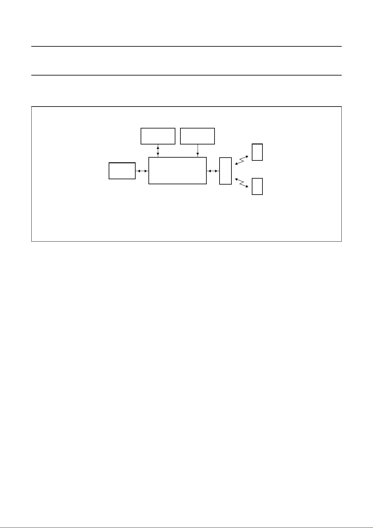
TheHITAGproximityreadermoduleHTRM440(seeFig.5)
is a part of a complete Radio Frequency Identification
(RFID) system:
• Transponders
• Antenna
• Host system
• I/O functions
• Power supply.
7.1.1 TRANSPONDERS
The HTRM440 communicates with HITAG 1 and HITAG 2
transponders. Software commands are used to switch
between the different transponder modes.
If several HITAG transponders arrive simultaneously
within the communication field of the antenna of a
HTRM440, the ‘stronger’ transponder (the nearer one)
takes over or - under special circumstances - no
communication takes place. If the transponders arrive into
the field one after the other, communication is established
with the first one, all the other transponders are ignored.
Nevertheless it is possible to mute transponders, so that
several HITAG transponders can be accessed
sequentially. This ensures that no two (or several) HITAG
transponders will ever be processed (above all written to!)
accidentally at the same time.
7.1.2 ANTENNA
Capacitor C (see Fig.1) is used for tuning the antenna.
There is space reserved on the HTRM440 for tuning
capacitors to tune the antenna in case there is no tuning
capacitor used on the antenna itself.
7.1.3 HOST SYSTEM
The connection to the host system (e.g. microcontroller
or PC) is a serial interface on RS232 level for data
transmission (version HTRM440/AIE). Optionally wired
interface drivers for CMOS (version HTRM440/BIE) and
RS485 (version HTRM440/CIE) are integrated on the
reader module.
7.1.4 INPUT AND OUTPUT FUNCTIONS
Two lines of the HTRM440 are wired as inputs from e.g.
switches and two lines as outputs to drive LEDs. On the
PCB space is reserved to connect three LEDs as well as
to connect e.g. two switches.
7.1.5 POWER SUPPLY
The HTRM440 must be supplied by an external DC power
supply (9 to 16 V).
2001 Oct 04 6
Page 7

Philips Semiconductors Product specification
HITAG proximity reader module
hardware
7.2 Reader module software
Software commands mentioned in this data sheet are fully
described in document
HTRM800 Family Interface Protocol Reader - Host”
7.3 Reader module hardware
7.3.1 CORE MODULE
The EEPROM on the core module HTCM400 (see Fig.1)
is used to store non-volatile data such as personalization
data, keys, passwords, configurations and status
information.
The microcontroller processes the protocol for the
communication between the transponders and the reader
module. The interface signals are converted in such a way
that HITAG 1 and HITAG 2 transponders are able to
process them and the outgoing signals from the
transponder are converted into interface-compatible
signals. The second essential microcontroller function is
its control function. The microcontroller activates and
deactivates the transmitter, switches thereceiver between
the modes for the different transponders reception and
selects the EEPROM.
The transmitter receives data from the microcontroller and
modulates the carrier.
The receiver demodulates the received data and passes
on the data to the microcontroller for further processing.
7.3.2 INTERFACE MICROCONTROLLER TO HOST
The device communicates with the host
(e.g. microcontroller or PC) via a serial interface using a
baud rate of 9600 baud. Data transfer details are: 1 start
bit, 8 data bits, 1 stop bit, no parity bit and the least
significant bit is sent first.
7.3.3 VOLTAGE REGULATION FILTERING
Disturbances on the supply pins may reduce the
performance of the system. For that reason the supply
voltageis filtered but also to limitthe spurious emissions at
the supply connections caused by the digital parts of the
module.
“HTCM400, HTRM440 Family,
.
HTRM440 family
Electromagnetic emissions comply with the guidelines in
FTZ 17 TR 2100 and ETS 300 683 and electromagnetic
immunity complies with the guidelines in ETS 300 683.
7.5 Security considerations
DevelopingtheHTRM440specialconsiderationwasgiven
to aspects of security. The following items represent the
fundamental framework of the security concept:
• Cryptography
• Mutual authentication
• Password verification
• Cyclic Redundancy Check (CRC).
7.5.1 DATA STREAM BETWEEN READER MODULE AND
HITAG 1 TRANSPONDERS
All the commands and data transferred from the reader
module to the transponder are secured by Cyclic
Redundancy Check (CRC). This check is carried out on
the transponder.
Every data stream sent (commands, addresses, user
data) from the proximity reader module to the transponder
is first checked for data errors by the transponder by
means of an integrated 8-bit CRC generator and then
executed. Normally the transponder responds to each
data stream from the proximity reader module with an
acknowledgement signal or with a data block. The CRC is
formed over commands and addresses or the plain data
respectively and in case of crypto mode it is also
encrypted. The generator polynomial of the transponder
CRC generator reads: u8+u4+u3+u2+1 = 0x1D.
The CRC pre assignment is 0xFF.
Detailed instructions how to use and calculate CRC are
available at Philips in the following application note
“HT1 (resp. HT2) Transponder family, reliability and
integrity of data transmission”
7.5.2 DATA STREAM BETWEEN READER MODULE AND
HITAG 2 TRANSPONDERS
Every command sent from the reader module to the
transponder is checked for data errors by the transponder.
.
7.4 Postal approval
The postal approval can only be granted for final products,
not just for modules like the HTRM440. But the reader
module is designed in a way that it is possible to get the
postal approval for a system including the HTRM440.
2001 Oct 04 7
Standard commands transferred from the reader module
to the transponder are divided into two bit streams. The
second bit stream is generated by inverting the bits of the
first bit stream. This redundancy increases data security.
Page 8

Philips Semiconductors Product specification
HITAG proximity reader module
hardware
7.5.3 CHECKING USER DATA
This check is carried out on the HTRM440.
Security of the data read from the transponder by the
reader module remains with the user for reasons of
flexibility. Therefore, you can choose flexible check sums
and store them in the transponder memory together with
the data. You can protect sensitive data better than less
sensitive data, thus permitting optimized operation times.
7.5.4 DATA PRIVACY
The use of cryptography (stream cypher), mutual
authentication, and password verification prevents
monitoring and copying the data channel. Therefore, the
area of the transponder that only can be accessed
enciphered is called ‘secret area’.
To make use of cryptography for HITAG 1 transponders
you need:
• Keys to be used for initializing of the crypto block
• Logdata to be used for mutual authentication.
To make use of cryptography for HITAG 2 transponders
you need:
• A key which is used to initialize the crypto block using
HITAG 2 in crypto mode
• Passwords which are used for authentication for
HITAG 2 in password mode.
The transponders and the HTRM440 are provided with
identical transport keys and transport logdata so that you
can start operating them right away (see Table 1).
HTRM440 family
7.6 Operating security
The following mechanisms ensure the operating security
of the HITAG system:
• Anticollission mode
• Monitoring the supply voltage
• Detection of antenna rupture and antenna short-circuit.
7.6.1 ANTICOLLISION
In proximity reader applications using HITAG 1 or
HITAG 2 transponders, only one transponder is handled
even if there are several transponders within the
communication field of the antenna. In this case either no
communication takes place or the ‘stronger’ or closer
transponder takes over. By muting a selected transponder
(HALT mode) another transponder that is to be found in
the communication field of the antenna can be recognised.
7.6.2 MONITORING THE SUPPLY VOLTAGE
The supply voltage is controlled by a watchdog circuit
which triggers a system reset if the supply voltage drops
below 4.75 V or if the microcontroller fails.
7.6.3 DETECTION OF ANTENNA RUPTURE AND ANTENNA
SHORT
-CIRCUIT
TheHTRM440doesnotgetpermanentlydamagedincase
of an antenna rupture or a brief antenna short-circuit.
In order to offer our OEM clients high flexibility, the
configuration of the transponder memory, password, keys
and logdata can be changed. We strictly recommend to
rigorously restrict these possibilities for the end customers
(by setting the configuration page to read only, setting
password, keys and logdata to neither read nor write).
Table 1 Transport values predefined by Philips.
SYSTEM PARAMETER VALUE
HITAG 1 keyinit password 0x00000000
keys 0x00000000
logdata 0x00000000
HITAG 2 keyinit password 0x00000000
key 0x4D494B524F4E
password TAG 0xAA4854
password RWD 0x4D494B52
2001 Oct 04 8
Page 9

Philips Semiconductors Product specification
HITAG proximity reader module
HTRM440 family
hardware
8 ELECTRICAL SPECIFICATIONS
SYMBOL PARAMETER CONDITION MIN. TYP. MAX. UNIT
External power supply
V
P
I
P
Modulation
m
TX
m
RX
Interface to host
f
t
Antenna
d operating distance note 2 − 200 − mm
Temperature
T
oper
T
stg
DC supply voltage 9 − 16 V
DC supply current −−150 mA
modulation ratio of reader module
Amplitude Shift Keying (ASK) − 100 − %
to transponder
modulation ratio of transponder to
reader module
Amplitude Shift Keying (ASK);
note 1
−−−%
transmission speed − 9600 − baud
operating temperature −25 − +85 °C
storage temperature −40 − +85 °C
Notes
1. Modulation ratio depending on the distance between transponder and reader module.
2. Depending on antenna and type of transponder; three-wire cable, shielded.
2001 Oct 04 9
Page 10
Philips Semiconductors Product specification
HITAG proximity reader module
hardware
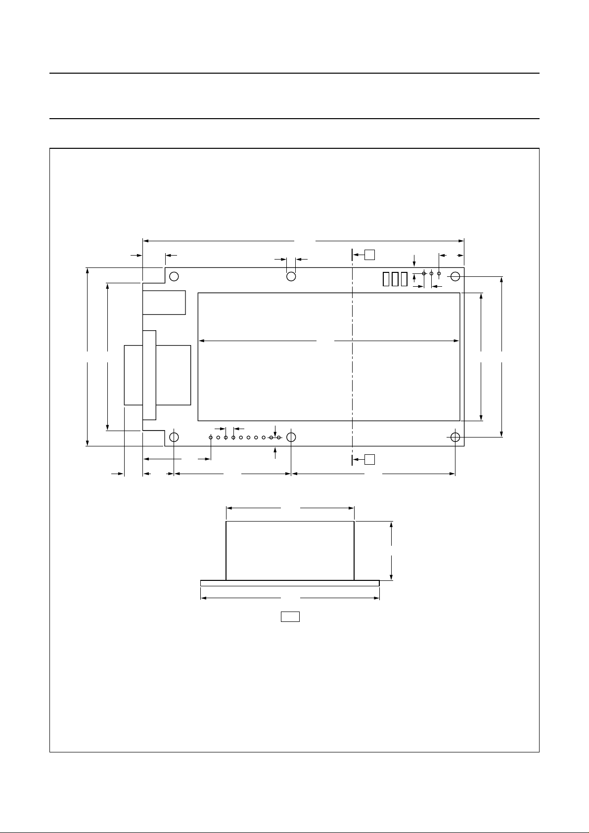
9 MECHANICAL SPECIFICATIONS
handbook, full pagewidth
7.5
49.560.0 43.0
3.0
108.1
88.0
HTRM440 family
A
2.0
8.5
2.54
54.0
Dimensions in mm.
6.3 10.0
22.8
40.0
2.54
2.9
43.0
60.0
A-A
A
55.0
MGW272
20.0
Fig.6 Proximity reader module.
2001 Oct 04 10
Page 11

Philips Semiconductors Product specification
HITAG proximity reader module
hardware
10 APPLICATION INFORMATION
10.1 Metallic environment, interferences
The communication range is impaired by metallic
environment and electromagnetic interferences
(e.g. monitors and keyboards). Therefore, you should
keep a distance of at least the antenna’s diameter to
metallic surfaces or loops as well as to electromagnetic
interferences. If this is not possible, you have to take
preventivemeasures such as using ferritesor shielding for
transponder and antenna.
10.2 Distance between two antennas
In order to be able to operate two systems side by side
without negative influence on communication ranges, you
must place the antennas at a minimum distance of four
times the antenna diameter. If you place them at a closer
distance be sure to use suitable shielding or
synchronisation.
HTRM440 family
• Interference received by the antenna because of an
external noise source (e.g. monitor, keyboards); the
remedial measure is to remove the antenna from the
interfering area
• Connecting cables of the antenna changed by mistake
• Antenna is mounted in metal environment; the remedial
measureistomountanon-metal space keeper between
the antenna and the metal
• Antenna is not designed following the design
instructions
• Inductance of the antenna is too high
• Quality factor of the antenna is too high (Q > 40)
• Antenna current is too high
• Antenna voltage is too high.
10.3 Possible sources of errors by connecting the
HTRM440
The following error list should be checked if any error
(e.g. readorwrite distances that do not reach the specified
values) occurs:
• Power supply cable not mounted correctly
• DC powersupply voltage not in thespecified range from
9to16V
• Serial interface not connected correctly
11 SURVEY OF REFERENCED DOCUMENTS
CATEGORY TITLE
Data sheet
Application note
“HTCM400, HTRM440 Family, HTRM800 Family Interface Protocol Reader - Host”
“HT1 (resp. HT2) Transponder family, reliability and integrity of data transmission”
2001 Oct 04 11
Page 12

Philips Semiconductors Product specification
HITAG proximity reader module
HTRM440 family
hardware
12 DATA SHEET STATUS
PRODUCT
DATA SHEET STATUS
Objective data Development This data sheet contains data from the objective specification for product
Preliminary data Qualification This data sheet contains data from the preliminary specification.
Product data Production This data sheet contains data from the product specification. Philips
Notes
1. Please consult the most recently issued data sheet before initiating or completing a design.
2. The product status of the device(s) described in this data sheet may have changed since this data sheet was
published. The latest information is available on the Internet at URL http://www.semiconductors.philips.com.
(1)
STATUS
(2)
development. Philips Semiconductors reserves the right to change the
specification in any manner without notice.
Supplementary data will be published at a later date. Philips
Semiconductors reserves the right to change the specification without
notice, in order to improve the design and supply the best possible
product.
Semiconductors reserves the right to make changes at any time in order
to improve the design, manufacturing and supply. Changes will be
communicated according to the Customer Product/Process Change
Notification (CPCN) procedure SNW-SQ-650A.
DEFINITIONS
13 DEFINITIONS
Short-form specification The data in a short-form
specification is extracted from a full data sheet with the
same type number and title. For detailed information see
the relevant data sheet or data handbook.
Limiting values definition Limiting values given are in
accordance with the Absolute Maximum Rating System
(IEC 60134). Stress above one or more of the limiting
values may cause permanent damage to the device.
These are stress ratings only and operation of the device
attheseorat any other conditions above those given in the
Characteristics sections of the specification is not implied.
Exposure to limiting values for extended periods may
affect device reliability.
Application information Applications that are
described herein for any of these products are for
illustrative purposes only. Philips Semiconductors make
norepresentationorwarrantythatsuchapplicationswillbe
suitable for the specified use without further testing or
modification.
14 DISCLAIMERS Life support applications These products are not
designed for use in life support appliances, devices, or
systems where malfunction of these products can
reasonably be expected to result in personal injury.Philips
Semiconductorscustomersusingorsellingtheseproducts
for use in such applications do so at their own risk and
agree to fully indemnify Philips Semiconductors for any
damages resulting from such application.
Right to make changes Philips Semiconductors
reserves the right to make changes, without notice, in the
products, including circuits, standard cells, and/or
software, described or contained herein in order to
improve design and/or performance. Philips
Semiconductors assumes no responsibility or liability for
theuseofanyoftheseproducts,conveysnolicenceortitle
under any patent, copyright, or mask work right to these
products,andmakes no representations or warranties that
these products are free from patent, copyright, or mask
work right infringement, unless otherwise specified.
2001 Oct 04 12
Page 13

Philips Semiconductors Product specification
HITAG proximity reader module
hardware
HTRM440 family
NOTES
2001 Oct 04 13
Page 14

Philips Semiconductors Product specification
HITAG proximity reader module
hardware
HTRM440 family
NOTES
2001 Oct 04 14
Page 15

Philips Semiconductors Product specification
HITAG proximity reader module
hardware
HTRM440 family
NOTES
2001 Oct 04 15
Page 16

Philips Semiconductors – a w orldwide compan y
Contact information
For additional information please visit http://www.semiconductors.philips.com. Fax: +31 40 27 24825
For sales offices addresses send e-mail to: [email protected].
© Koninklijke Philips Electronics N.V. 2001
All rights are reserved. Reproduction in whole or in part is prohibited without the prior written consent of the copyright owner.
The information presented in this document does not form part of any quotation or contract, is believed to be accurate and reliable and may be changed
without notice. No liability will be accepted by the publisher for any consequence of its use. Publication thereof does not convey nor imply any license
under patent- or other industrial or intellectual property rights.
Printed in The Netherlands 613502/02/pp16 Date of release: 2001 Oct 04 Document order number: 9397 750 08332
SCA73
 Loading...