

Page 1
Features
Operating voltage: 2.4V~12V
·
Low power and high noise immunity CMOS
·
technology
Low standby current
·
Minimum transmission word
·
-
Four words for TE trigger
-
One word for Data trigger
Applications
Burglar alarm system
·
Smoke and fire alarm system
·
Garage door controllers
·
Car alarm system
·
General Description
The 312encoders are a series of CMOS LSIs for
remote controlsystem applications. They are ca
pable of encoding 12 bits of information which
consists of N address bits and 12-N data bits.
Each address/data input is externally trinary
programmable if bonded out.They are otherwise
set floating internally. Various packages of the
12
3
encoders offer flexible combinations of
12
3
-
Series of Encoders
Built-in oscillator needs only 5% resistor
·
Easy interface with an RF or an infrared
·
transmission medium
Minimal external components
·
Package information: refer to Selection
·
Table
Security system
·
Cordless telephones
·
Other remote control systems
·
programmable address/data which meet vari
ous applications. The programmable ad
dress/data is transmitted together withthe header
bits via an RFor an infrared transmissionmedium
upon receipt of a trigger signal. A TE
a DATA (HT6012/HT6014) trigger can be selectedforapplicationflexibility.
-
-
(HT6010) or
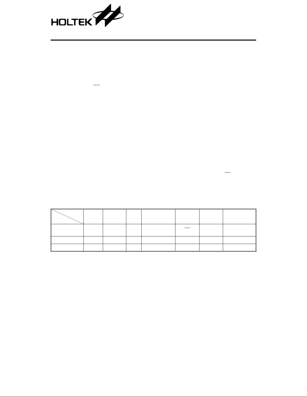
Selection Table
Function
Part No.
HT6010 8 4 0 RC oscillator TE
HT6012 10 0 2 RC oscillator D10~D11 Yes 18 DIP/20 SOP
HT6014 8 0 4 RC oscillator D8~D11 Yes 18 DIP/20 SOP
Note: Address/Data represents addressable pins or data according to the requirements of decoders.
Address
No.
Address/
Data No.
Data
No.
Oscillator Trigger
1 December 13, 1999
LED
Indicator
No
Package
18/20 DIP
20 SOP
Page 2
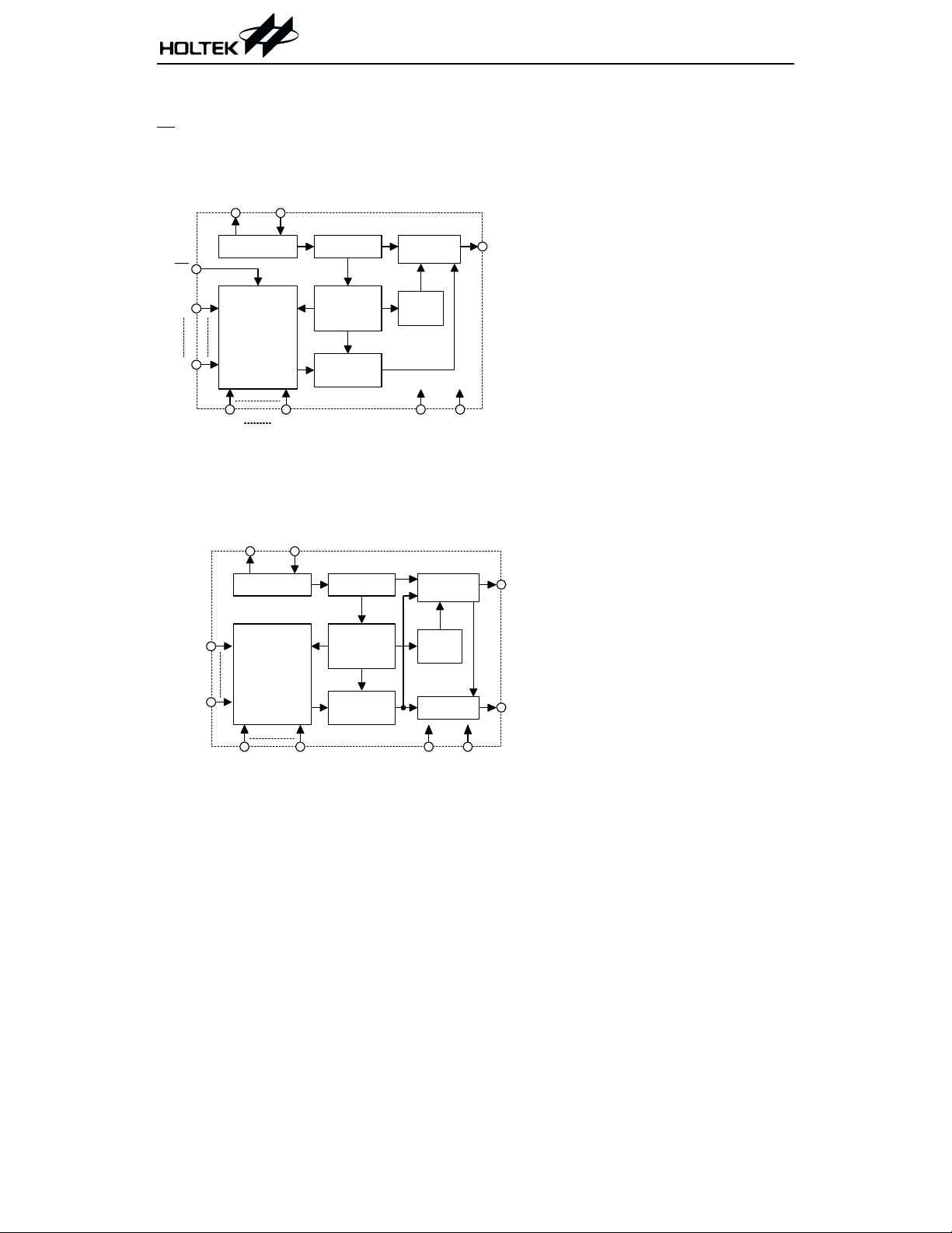
Block Diagram
TE trigger
HT6010
OSC2
312Series of Encoders
OSC1
O s c illa to r
TE
A0
A7
12
Transm ission
G a te C ir c u it
AD8 AD11
DATA trigger
HT6012/HT6014
OSC2
O scillator
Address
Transm ission
G a te C ir c u it
12
OSC1
3 D ivider
¸
12 C ounter
¸
and 1 of 12
D ecoders
Trinary
Detector
3 D iv id e r
¸
12 C ounter
¸
and 1 of 12
D ecoders
Trinary
Detector
D ata S elect
and Buffer
Sync.
Circuit
VDD VSS
D ata S elect
and Buffer
Sync.
Circuit
LED Circuit
DOUT
DOUT
LED
Data
VDD VSS
Note: The address/data pins are available in various combinations (refer to the address/data table).
2 December 13, 1999
Page 3
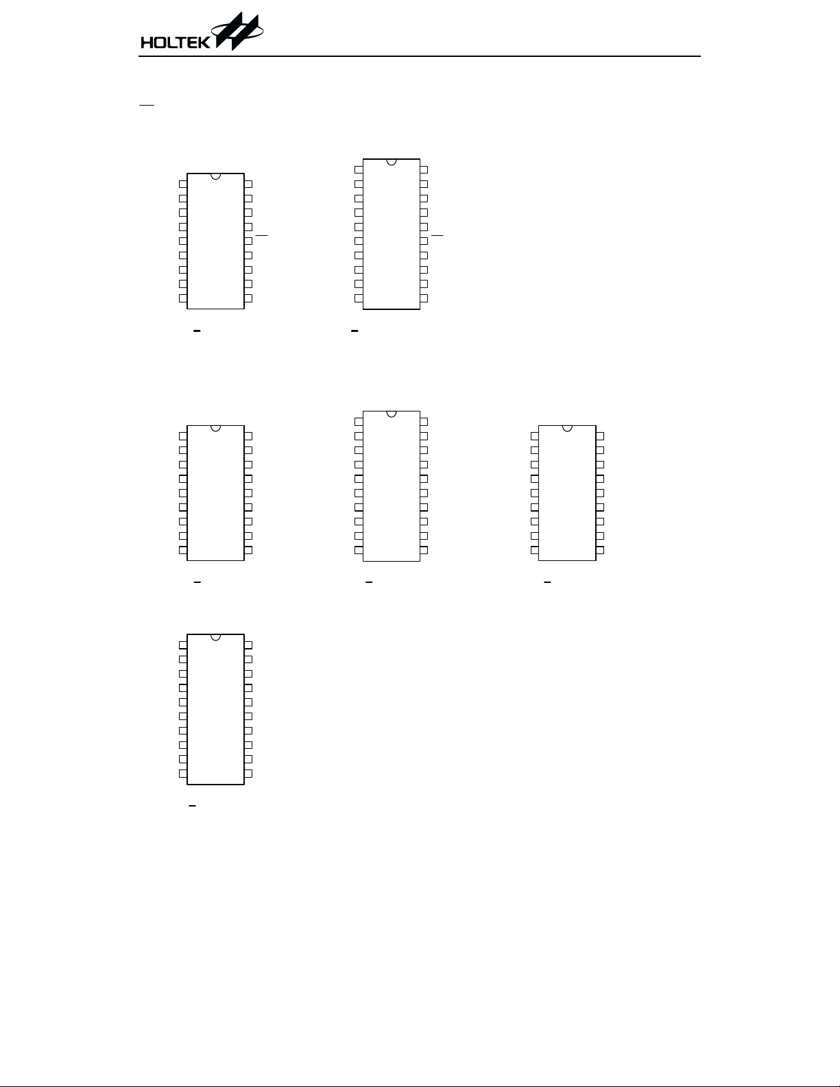
Pin Assignment
T E tr ig g e r ty p e
312Series of Encoders
8-A d dress
4-A ddress/D ata
A0
A1
A2
A3
A4
A5
A6
A7
VSS
18
1
17
2
16
3
15
4
14
5
13
6
12
7
11
8
10
9
H T6010
18 D IP
DATA trigger type
10-A ddress
2 -D a ta
1
A0
A1
A2
A3
A4
A5
A6
A7
VSS
18
2
17
3
16
4
15
5
14
6
13
7
12
8
11
9
10
H T6012
18 D IP
VDD
DOUT
OSC2
OSC1
TE
AD11
AD10
AD9
AD8
VDD
DOUT
OSC2
OSC1
LED
D11
D10
A9
A8
8-A d dress
4-A ddress/D ata
NC
1
A0
2
A1
3
A2
4
A3
5
A4
6
A5
7
A6
8
A7
9
VSS
10
H T 6010
20 D IP/SOP
10-A ddress
2 -D a ta
NC
1
A0
2
A1
3
A2
4
A3
5
A4
6
A5
7
A6
8
A7
9
VSS
10
H T6012
2 0 S O P
NC
20
VDD
19
DOUT
18
OSC2
17
OSC1
16
TE
15
AD11
14
AD10
13
AD9
12
AD8
11
8-A d dress
4 -D a ta
20
NC
19
VDD
18
DOUT
17
OSC2
16
OSC1
15
LED
14
D11
13
D10
12
A9
11
A8
A0
A1
A2
A3
A4
A5
A6
A7
VSS
1
18
2
3
4
5
6
7
8
9
VDD
17
DOUT
16
OSC2
15
OSC1
14
LED
13
D11
12
D10
11
D9
10
D8
H T6014
18 D IP
8-A d dress
4-D ata
NC
1
A0
2
A1
3
A2
4
A3
5
A4
6
A5
7
A6
8
A7
9
VSS
10
H T6014
2 0 S O P
NC
20
VDD
19
DOUT
18
OSC2
17
OSC1
16
LED
15
D11
14
D10
13
D9
12
D8
11
3 December 13, 1999
Page 4
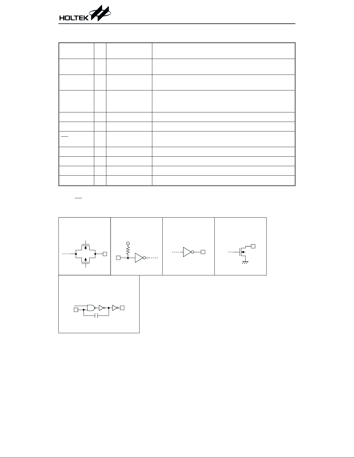
Pin Description
312Series of Encoders
Pin Name I/O
A0~A9 I
AD8~AD11 I
D8~D11 I
Internal
Connection
TRANSMISSION
GATE
TRANSMISSION
GATE
CMOS IN
Pull-high
Description
Input pins for address A0~A9 setting
They can be externally set to VDD or VSS or left open.
Input pins for address/data (AD8~AD11) setting
They can be externally set to VDD or VSS or left open.
Input pins for data (D8~D11) setting and transmission en
able (active low)
They can be externally set to VSS or left open (see Note).
DOUT O CMOS OUT Encoder data serial transmission output
LED O NMOS OUT Transmission enable indicator, active low
TE
I
CMOS IN
Pull-high
Transmission enable, active low (see Note)
OSC1 I OSCILLATOR Oscillator input pin
OSC2 O OSCILLATOR Oscillator output pin
VSS
VDD
¾¾
¾¾
Negative power supply, ground
Positive power supply
Note: D8~D11 are data input and transmission enable pins of the HT6012/HT6014.
TE
is the transmission enable pin of the HT6010.
Approximate internal connections
-
TRANSM ISSIO N
GATE
OSCILLATOR
EN
OSC1
CMOS IN
Pull-high
OSC2
CMOS OUT NMOS OUT
4 December 13, 1999
Page 5

Absolute Maximum Ratings
312Series of Encoders
Supply Voltage...............................-0.3V to 13V
Input Voltage....................V
-0.3 to VDD+0.3V
SS
Storage Temperature.................-50°Cto125°C
Operating Temperature ..............-20°Cto75°C
Note: These are stress ratings only. Stresses exceeding the range specified under ²Absolute Maxi
mum Ratings² may cause substantial damage to the device. Functional operation of this device
at other conditions beyond those listed in the specification is not implied and prolonged expo
sure to extreme conditions may affect device reliability.
Electrical Characteristics
Ta=25°C
Test Conditions
Symbol Parameter
V
DD
I
STB
I
DD
I
LED
I
DOUT
V
IH
V
IL
f
OSC
R
TE
R
DATA
Operating Voltage
Standby Current
Operating Current
LED Sink Current 5V
Output Drive Current
²H² Input Voltage ¾¾
²L² Input Voltage ¾¾
Oscillator Frequency 5V
TE Pull-high Resistance 5V
D8~D11 Pull-high
Resistance
V
DD
Conditions
¾¾
3V
Oscillator stops
12V
3V
No load
=3kHz
f
OSC
12V
V
=0.5V
LED
V
5V
5V
5V
=0.9VDD(Source)
OH
V
=0.1VDD(Sink)
OL
=1MW¾3¾
R
OSC
V
=0V
TE
=0V
V
DATA
Min. Typ. Max. Unit
2.4 5 12 V
DD
0
0.1 1
24
250 500
600 1200
¾
¾
V
¾
¾
0.2V
DD
DD
mA
mA
mA
¾
¾
¾
¾
1.5 3
-0.6 -1.2 ¾
0.6 1.2
0.8V
kHz
¾
¾
1.5 3
1.5 3
MW
MW
mA
mA
mA
mA
V
V
-
-
5 December 13, 1999
Page 6

312Series of Encoders
Functional Description
Operation
12
The 3
cycle upon receipt of a transmission enable (TE
tive low). This cycle will repeat itself as long as the transmission enable (TE
Once the transmission enable returns high the encoder output completes its final cycle and then stops
as shown below.
Information word
An information word is composed of four periods as shown:
series of encoders begin with a four (HT6010) or a one (HT6012/HT6014) word transmission
for the HT6010 or D8~D11 for the HT6012/HT6014, ac
or D8~D11) is held low.
TE or
D 8~D 11
< 1 w ord
Encoder
Data Out
1 or 4 w ords
Transm itted
C ontinuously
1 or 4
words
Transmission timing
1/6 bit sync. period
-
pilot period (6 bits)
address code period
Composition of information
6 December 13, 1999
data code
period
Page 7

312Series of Encoders
Address/data waveform
Each programmable address/data pin can be externally set to one of the following three logic states:
f
OSC
"O n e"
"Z ero"
"O pen"
Address/D ata B it
Address/Data bit waveform
The ²Open² state data input is interpreted as logic high by the decoder since its output has only two
states.
Address/data programming (preset)
The status of each address/data pin can be individually preset to a logic ²high², ²low²,or²floating².If
a transmission enable signal is applied, the encoder scans and transmits the status of the 12 bits of
address/data serially in the order A0 to AD11 for the HT6010 and A0 to D11 for the HT6012/HT6014.
If the trigger signal is not applied, the chip only consumes a standby current which is less than 1mA
DD
=5V).
(for V
The address pins are usually preset so as to transmit data codes with their own particular security codes
by the DIP switches or PCB wiring, while data is selected using push button or electronic switches.
Address/Data sequence
The following table provides the position of the address/data sequence for various models of the 3
series encoders. A correct device should be selected according to the requirements of the individual
address and data.
Address/Data Bits
Part No.
01234567891011
HT6010 A0 A1 A2 A3 A4 A5 A6 A7 AD8 AD9 AD10 AD11
HT6012 A0 A1 A2 A3 A4 A5 A6 A7 A8 A9 D10 D11
HT6014 A0 A1 A2 A3 A4 A5 A6 A7 D8 D9 D10 D11
7 December 13, 1999
12
Page 8

312Series of Encoders
Transmission enable
For the TE
But for the Data trigger type, it is enabled by applying a low signal to one of the data pins D8~D11.
Flowchart
trigger type of encoders, transmission is enabled by applying a low signal to the TE pin.
Power on
Standby m ode
No
No
Transm ission
enabled ?
Yes
C ode w ord
transm itted
continuously
Transm ission
still enabled ?
Yes
C ode w ord
transm itted
continuously
Note: D8~D11 are transmission enable of the HT6012/HT6014.
is the transmission enable of the HT6010.
TE
8 December 13, 1999
Page 9

Oscillator frequency vs supply voltage
OSC
f
(S cale)
7.00
6.00
5.00
4.00
(3kH z)3.0 0
312Series of Encoders
OSC
(W)
R
470k
510k
560k
620k
680k
750k
820k
910k
1.0M
1.2M
2.00
1.00
2 3 4
5 6 7 8 9 10 11 12 13
The recommended oscillator frequency is f
(decoder) @ 33 f
OSCD
OSCE
1.5M
2.0M
VDD (V D C )
(encoder)
9 December 13, 1999
Page 10

Application Circuits
312Series of Encoders
Transm itter C ircuit
1
A0
2
A1
3
A2
4
A3
5
A4
6
A5
7
A6
8
A7
9
VSS
VDD
DOUT
OSC2
OSC1
TE
AD11
AD10
AD9
AD8
H T 6010
Transm itter C ircuit
1
A0
2
A1
3
A2
4
A3
5
A4
6
A5
7
A6
8
A7
9
VSS
VDD
DOUT
OSC2
OSC1
LED
D11
D10
D9
D8
V
DD
18
17
16
R
OSC
15
14
13
12
11
10
Transm itter C ircuit
1
A0
2
A1
3
A2
4
A3
5
A4
6
A5
7
A6
8
A7
9
VSS
VDD
DOUT
OSC2
OSC1
LED
D11
D10
A9
A8
V
DD
18
17
16
R
OSC
15
14
13
12
11
10
R
H T 6012
V
DD
18
17
16
R
OSC
15
14
13
12
11
10
R
H T 6014
Note: Typical infrared diode: EL-1L2 (KODENSHI CORP.)
Typical RF transmitter: JR-220 (JUWA CORP.)
TX-99 (MING MICROSYSTEM, U.S.A.)
10 December 13, 1999
Page 11

312Series of Encoders
Holtek Semiconductor Inc. (Headquarters)
No.3 Creation Rd. II, Science-based Industrial Park, Hsinchu, Taiwan, R.O.C.
Tel: 886-3-563-1999
Fax: 886-3-563-1189
Holtek Semiconductor Inc. (Taipei Office)
5F, No.576, Sec.7 Chung Hsiao E. Rd., Taipei, Taiwan, R.O.C.
Tel: 886-2-2782-9635
Fax: 886-2-2782-9636
Fax: 886-2-2782-7128 (International sales hotline)
Holtek Semiconductor (Hong Kong) Ltd.
RM.711, Tower 2, Cheung Sha Wan Plaza, 833 Cheung Sha Wan Rd., Kowloon, Hong Kong
Tel: 852-2-745-8288
Fax: 852-2-742-8657
Copyright Ó 1999 by HOLTEK SEMICONDUCTOR INC.
The information appearing in this Data Sheet is believed to be accurate at the time of publication. However, Holtek
assumes no responsibility arising from theuse ofthe specifications described. The applications mentioned herein are
used solely for the purpose of illustration and Holtek makes no warranty or representation that such applications
will be suitable without further modification, nor recommends the use of its products for application that may pres
ent a risk to human life due to malfunction or otherwise. Holtek reserves the right to alter its products without prior
notification. For the most up-to-date information, please visit our web site at http://www.holtek.com.tw.
11 December 13, 1999
-
 Loading...