

HS-508BRH
Data Sheet December 1999
Radiation Hardened 8 Channel CMOS
Analog Multiplexer with Overvoltage
Protection
The HS-508BRH is a dielectrically isolated, radiation
hardened, CMOS analog multiplexer incorporating an
important feature; it withstands analog input voltages much
greater than the supplies. This is essential in any system
where the analog inputs originate outside the equipment.
They can withstand a continuous input up to 10V greater than
either supply, which eliminates thepossibilityofdamagewhen
supplies are off, but input signals are present. Equally
important, it can withstand brief input transient spikes of
severalhundredvolts; which otherwise would require complex
external protection networks. Necessarily, ON resistance is
somewhat higher than similar unprotected devices, but very
low leakage current combine to produce low errors.
Reference Application Notes 520 and 521 for further
information on the HS-508BRH multiplex er in gener al.
The HS-508BRH has been specifically designed to meet
exposuretoradiationenvironments. Operation from -55
o
125
C is guaranteed.
o
Cto
Ordering Information
INTERNAL
ORDERING NUMBER
5962R9674202QEC HS1-508BRH-8 -55 to 125
5962R9674202QXC HS9-508BRH-8 -55 to 125
5962R9674202VEC HS1-508BRH-Q -55 to 125
5962R9674202VXC HS9-508BRH-Q -55 to 125
HS1-508BRH/PROTO HS1-508BRH/PROTO -55 to 125
HS9-508BRH/PROTO HS9-508BRH/PROTO -55 to 125
MKT. NUMBER
TEMP.
RANGE (oC)
File Number 4824
Features
• Electrically Screened to SMD # 5962-96742
• QML Qualified per MIL-PRF-38535 Requirements
• Radiation Environment
- Gamma Dose (γ) . . . . . . . . . . . . . . . . . 3 x 10
- Dielectrically Isolated Device Islands
- SEP >100 Mev-mg/cm
2
• Analog/Digital Overvoltage Protection
• ESD Rated to 3KV
• Fail Safe with Power Loss (No Latchup)
• Break-Before-Make Switching
• DTL/TTL and CMOS Compatible
• Analog Signal Range. . . . . . . . . . . . . . . . . . . . . . . . . . . .±15V
• Fast Access Time
• Supply Current at 1MHz Address Toggle. . . . . .4mA (Typ)
• Standby Power . . . . . . . . . . . . . . . . . . . . . . . .7.5mW (Typ)
Specifications for Rad Hard QML devices are controlled
by the Defense Supply Center in Columbus (DSCC). The
SMD numbers listed here must be used when ordering.
Detailed Electrical Specifications for these devices are
contained in SMD 5962-96742. A “hot-link” is provided
on our homepage for downloading.
www.intersil.com/spacedefense/newsafclasst.asp
5
RAD(Si)
Pinouts
HS1-508BRH 16 LEAD SIDEBRAZE DIP
MIL-STD-1835, CDIP2-T16
TOP VIEW
16
15
14
13
12
11
10
9
A1
A2
GND
+VSUP
IN 5
IN 6
IN 7
IN 8
AO
EN
-VSUP
IN 1
IN 2
IN 3
IN 4
OUT
1
2
3
4
5
6
7
8
1
HS9-508BRH 16 LEAD FLATPACK
MIL-STD-1835, CDFP4-F16
TOP VIEW
A0 A1
EN
-VSUP
IN1
IN2
IN3
IN4
OUT
CAUTION: These devices are sensitive to electrostatic discharge; follow proper IC Handling Procedures.
1-888-INTERSIL or 321-724-7143
116
2
3
4
5
6
7
8
15
14
13
12
11
10
9
| Copyright © Intersil Corporation 1999
A2
GND
+VSUP
IN5
IN6
IN7
IN8
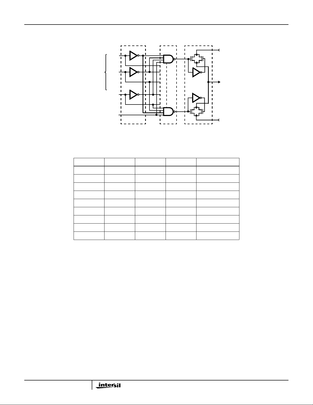
Functional Diagram
HS-508BRH
IN 1
OUT
IN 8
DIGITAL
ADDRESS
A0
A1
A2
EN
LEVEL SHIFTER
BUFFER AND
P
N
1
8
DECODERSADDRESS INPUT
N
P
MULTIPLEX
SWITCHES
TRUTH TABLE
A2 A1 A0 EN “ON” CHANNEL
X X X L NONE
LLLH 1
LLHH 2
LHLH 3
LHHH 4
HLLH 5
HLHH 6
HHLH 7
HHHH 8
2
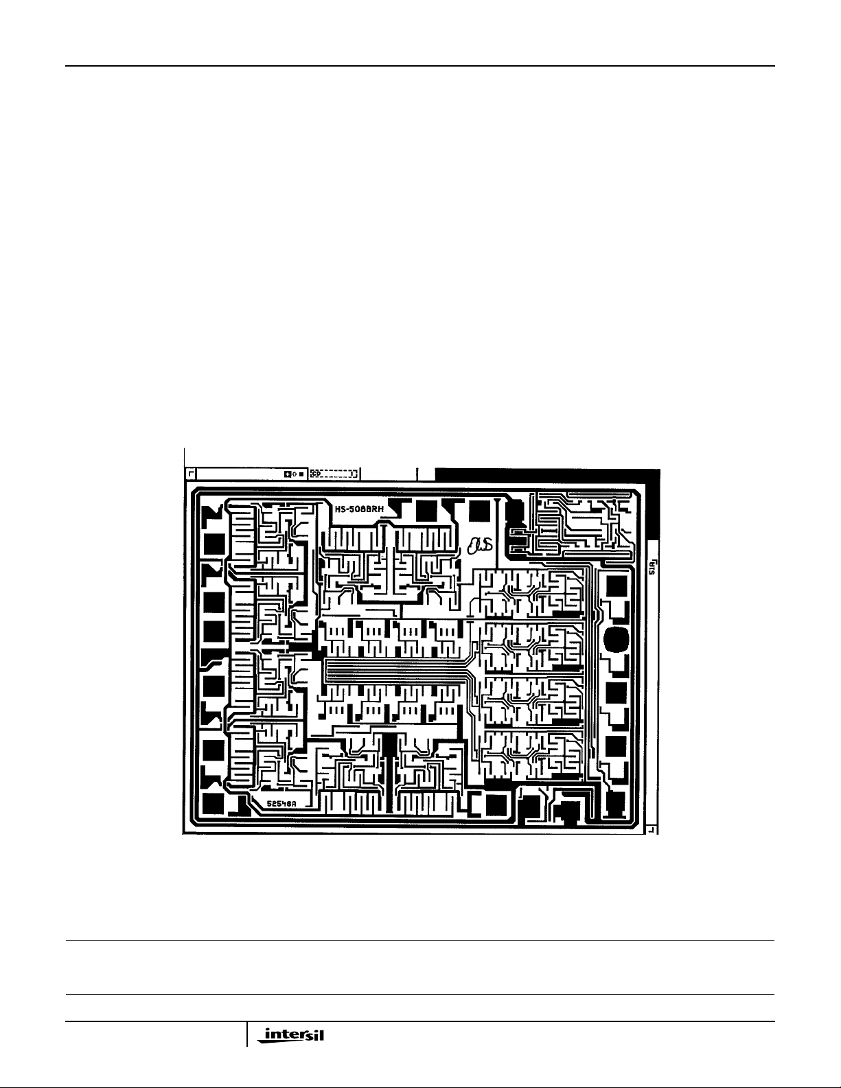
Die Characteristics
HS-508BRH
DIE DIMENSIONS:
120 mils x 93 mils x 19 mils
INTERFACE MATERIALS:
Glassivation:
Type: Phosphorus Silicon Glass (PSG)
Thickness: 8k
Å ±1kÅ
Top Metallization:
Type: AlSiCu
Thickness: 16k
Å ±2kÅ
Substrate:
Rad Hard Silicon Gate
Dielectric Isolation
Metallization Mask Layout
Backside Finish:
ASSEMBLY RELATED INFORMATION:
Substrate Potential:
ADDITIONAL INFORMATION:
Worst Case Current Density:
Transistor Count:
HS-508BRH
IN2 IN1 -V
Silicon
Unbiased (DI)
6.68e04 A/cm
506
2
IN3
IN4
OUT
IN8
IN7
IN6
IN5 +V GND
EN
A0
A1
A2
All Intersil semiconductor products are manufactured, assembled and tested under ISO9000 quality systems certification.
Intersil semiconductor products are sold by description only. Intersil Corporation reserves the right to make changes in circuit design and/or specifications at any time without notice. Accordingly ,the reader is cautioned to verify that data sheets are current before placing orders. Information furnished by Intersil is believed to be accurate and
reliable. However, no responsibility is assumed by Intersil or its subsidiaries for its use; nor for any infringements of patents or other rights of third parties which may result
from its use. No license is granted by implication or otherwise under any patent or patent rights of Intersil or its subsidiaries.
For information regarding Intersil Corporation and its products, see web site www.intersil.com
3
 Loading...