

Page 1
MICROWAVE CORPORATION
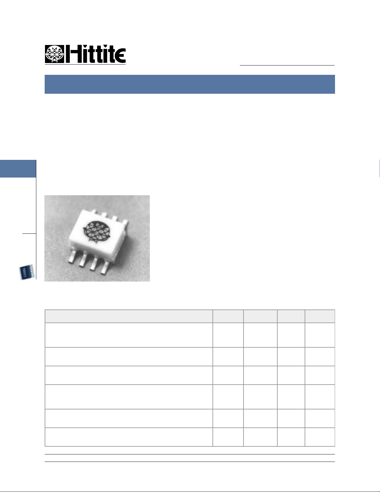
HMC121C8
GaAs MMIC SMT VOLTAGE-VARIABLE ATTENUATOR DC - 10 GHz
2
ATTENUATORS
SMT
FEBRUARY 2001
Features
WIDE BANDWIDTH: DC - 10 GHz
LOW PHASE SHIFT VS. ATTENUATION
25 dB ATTENUATION RANGE
SIMPLIFIED VOLTAGE CONTROL
V03.0400
General Description
The HMC121C8 is an absorptive Voltage
Variable Attenuator (VVA) in a non-hermetic
surface-mount package covering DC - 10
GHz. It features an on-chip reference attenuator for use with an external op-amp to
provide simple single voltage attenuation
control, 0 to -3V. The device is ideal in
designs where an analog DC control signal
must control RF signal levels over a 25 dB
amplitude range. Applications include AGC
circuits and temperature compensation of
multiple gain stages in microwave point-topoint and VSAT radios. See HMC121G8
for a hermetic SMT version of this device.
Guaranteed Perf ormance, 50 ohm system, -55 to +85 deg C
Parameter Min Typical Max Units
Insertion Loss DC -6 GHz :
Attenuation Range DC - 6 GHz:
Return Loss DC -8 GHz:
S witching Characteristics
tRISE,tFALL (10/90% RF):
tON, tOFF (50% CTL to 10/90% R F):
Input Power for 0. 25 dB Compression
(0.5 - 10 GHz)
Input Third Order Intercept (two - 8 dBm
signals, 0.5 - 10 GHz)
12 Elizabeth Drive, Chelmsford, MA 01824 Phone: 978-250-3343 Fax: 978-250-3373 Web Site: www.hittite.com
DC -8 GHz:
DC -10 GHz :
DC - 10 GHz:
DC - 10 GHz:
Min. Atten:
Atten.>2 dB:
Min. Atten: +18
20
25
11
8
2 - 14
2.0
2.2
3.5
25
30
15
12
3
6
+3
-3
+10
2.5
3.2
4.5
dB
dB
dB
dB
dB
dB
ns
ns
dBm
dBm
dBm
dBm
Page 2
HMC121C8
MICROWAVE CORPORATION
HMC121C8 SMT VOLTAGE-VARIABLE ATTENUATOR DC - 10 GHz
V03.0400
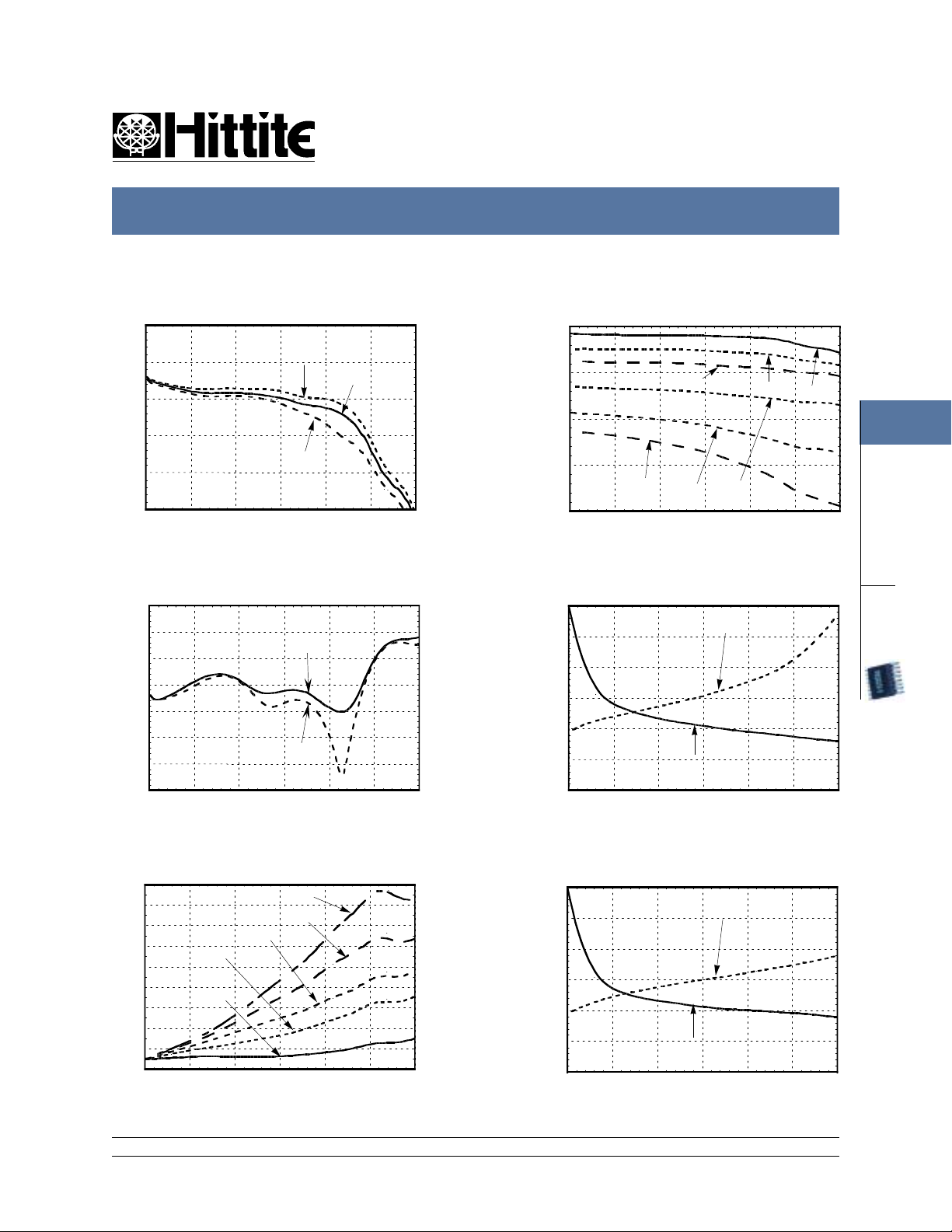
Insertion Loss Relative Attenuation
0
-1
-2
-3
INSERTION LOSS (dB)
-4
-5
024681012
FREQUENCY (GHz)
-40 C
+25 C
+85 C
0
-10
-20
ATTENUATION (dB)
-30
24 dB
-40
024681012
6dB
18 dB
FREQUENCY (GHz)
Relative Attenuation vs.
Return Loss
0
-5
-10
-15
-20
-25
RETURN LOSS (dB)
-30
-35
024681012
FREQUENCY (GHz)
S11
S22
Control Voltage @ 4.2 GHz
0
-0.5
-1
-1.5
-2
CONTROL VOLTAGE (Vdc)
-2.5
-3
0 5 10 15 20 25 30
RELATIVE ATTENUATION (dB)
V1
Relative Attenuation vs.
Relative Phase
85
75
65
55
45
35
25
15
RELATIVE PHASE (DEG)
5
-5
024681012
9dB
3dB
24 dB
21 dB
15 dB
FREQUENCY (GHz)
Control Voltage @ 10 GHz
0
-0.5
-1
-1.5
-2
CONTROL VOLTAGE (Vdc)
-2.5
-3
0 5 10 15 20 25 30
RELATIVE ATTENUATION (dB)
V1
FEBRUARY 2001
3dB
12 dB
V2
V2
0dB
2
ATTENUATORS
SMT
12 Elizabeth Drive, Chelmsford, MA 01824 Phone: 978-250-3343 Fax: 978-250-3373 Web Site: www.hittite.com
2 - 15
Page 3

HMC121C8
MICROWAVE CORPORATION
HMC121C8 SMT VOLTAGE-VARIABLE ATTENUATOR DC - 10 GHz
2
ATTENUATORS
SMT
FEBRUARY 2001
Input Third Order
Intercept vs. Attenuation
30
25
20
15
10
THIRD ORDER INTERCEPT (dBm)
5
012345678910
Reference
10 dB
6dB
3dB
FREQUENCY (GHz)
0.25 dB Compression
vs. Attenuation
15
10
5
6dB
0
-5
0.25 dB COMPRESSION (dBm)
-10
012345678910
Reference
FREQUENCY (GHz)
Input Second Order
Intercept vs. Attenuation
SECOND ORDER INTERCEPT (dBm)
60
50
40
30
20
10
Reference
6dB
012345678910
FREQUENCY (GHz)
10 dB
1 dB Compression
vs. Attenuation
15
Reference
10
5
0
-5
1 dB COMPRESSION (dBm)
-10
012345678910
6dB
FREQUENCY (GHz)
V03.0400
3dB
Second Harmonic vs. Attenuation
70
Reference
60
50
40
SECOND HARMONIC (dBc)
30
012345678910
FREQUENCY (GHz)
12 Elizabeth Drive, Chelmsford, MA 01824 Phone: 978-250-3343 Fax: 978-250-3373 Web Site: www.hittite.com
2 - 16
3dB
6dB
10 dB
Page 4

HMC121C8
MICROWAVE CORPORATION
HMC121C8 SMT VOLTAGE-VARIABLE ATTENUATOR DC - 10 GHz
V03.0400
Schematic
50 50
500
Outline Drawing
FEBRUARY 2001
Absolute Maximum Ratings
RF Input +16dBm
RF2RF1
500500
500
V1OIV2
Control Voltage Range +1.0 to -6.0 Vdc
Storage Temperature -65 to +150 deg C
Operating Temperature -55 to +85 deg C
2
ATTENUATORS
SMT
1. MATERIAL:
A) PACKAGE BODY & COVER : WHITE ALUMINA (92%)
B) LEADS & PACKAGE BOTTOM: COPPER
2 . PLATING : ELECTROLYTIC GOLD 100 - 200 MICROINCHES
OVER ELECTROLYTIC NICKEL 100 TO 200 MICROINCHES.
3. DIMENSIONS ARE IN INCHES (MILLIMETERS).
UNLESS OTHERWISE SPECIFIED TOL. ARE ±0.005(±0.13).
4. ALL UNLABELED LEADS ARE GROUND. THESE LEADS ARE
CONNECTED INTERNALLY TO THE PACKAGED BOTTOM GROUND.
THE PACKAGE BOTTOM RF GROUND MUST BE SOLDERED TO
THE PCB RF GROUND.
5. PACKAGE LENGTH AND WIDTH DIMENSIONS SHOWN DO NOT INCLUDE
LID SEAL PROTRUSION. ALLOWABLE PROTRUSION SHALL BE 0.005
(0.127MM) PER SIDE.
12 Elizabeth Drive, Chelmsford, MA 01824 Phone: 978-250-3343 Fax: 978-250-3373 Web Site: www.hittite.com
2 - 17
Page 5

HMC121C8
MICROWAVE CORPORATION
HMC121C8 SMT VOLTAGE-VARIABLE ATTENUATOR DC - 10 GHz
2
ATTENUATORS
SMT
FEBRUARY 2001
Single-Line Control Driver
50 50
500
3.9K
1N4148
3.9K500
+5V
TL321
OR EQUIVALENT
V02.0400
RF2RF1
500500
500
V1OIV2
CTL
500
-5V
External op-amp control circuit maintains impedance match while attenuation is varied. Input control ranges
from 0 Volts (min. attenuation) to -2.5 Volts (max. attenuation.)
12 Elizabeth Drive, Chelmsford, MA 01824 Phone: 978-250-3343 Fax: 978-250-3373 Web Site: www.hittite.com
2 - 18
Page 6

HMC121C8
MICROWAVE CORPORATION
HMC121C8 SMT VOLTAGE-VARIABLE ATTENUATOR DC - 10 GHz
V02.0400
Evaluation PCB
FEBRUARY 2001
2
ATTENUATORS
SMT
The circuit board used in the final application should be generated with proper RF circuit design techniques.
Signal lines at the RF port should have 50 ohm impedance and the package ground leads and package bottom
ground should be connected directly to the ground plane similar to that shown above. The evaluation circuit
board shown above is available from Hittite Microwave Corporation upon request.
List of Material
Item Description
J1 - J2 PC Mount SMA RF Connector
J3- J7 DCPIN
U1 HMC121C8
PCB
*
* Circuit Board Material : Rogers 4350
12 Elizabeth Drive, Chelmsford, MA 01824 Phone: 978-250-3343 Fax: 978-250-3373 Web Site: www.hittite.com
102084 Eval Board
VVA
2 - 19
 Loading...