

Page 1

INTEGRATED CIRCUITS
DATA SH EET
For a complete data sheet, please also download:
•The IC04 LOCMOS HE4000B Logic
Family Specifications HEF, HEC
•The IC04 LOCMOS HE4000B Logic
Package Outlines/Information HEF, HEC
HEF4752V
LSI
A.C. motor control circuit
Product specification
File under Integrated Circuits, IC04
January 1995
Page 2
Philips Semiconductors Product specification
A.C. motor control circuit
DESCRIPTION
The HEF4752V is a circuit for a.c. motor speed control
utilizing LOCMOS technology. The circuit synthesizes
three 120° out of phase signals, of which the average
voltage varies sinusoidally with time in the frequency
range 0 to 200 Hz. The method employed is based upon
the pulse width modulation principle, in order to achieve a
sufficient accuracy of the output voltages over the whole
frequency range. A pure digital waveform generation is
used.
All outputs are of the push-pull type. Inputs and outputs are
protected against electrostatic effects in a wide variety of
device-handling situations. However, to be totally safe, it is
desirable to take handling precautions into account.
HEF4752V
LSI
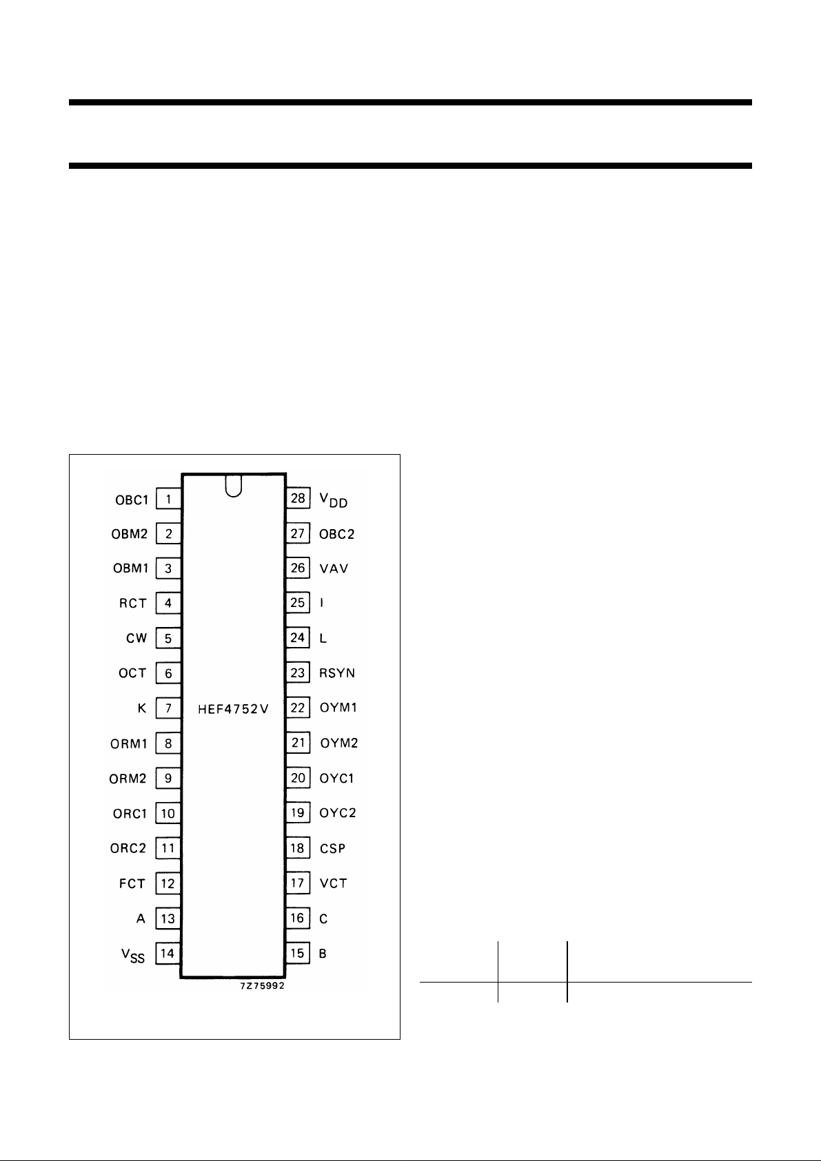
PINNING
Inputs; group I
24 = L data
25 = I data
7 = K data
5 = CW data
13 = A data
15 = B data
16 = C data
Inputs; group II
12 = FCT frequency clock
17 = VCT voltage clock
4 = RCT reference clock
6 = OCT output delay
clock
Outputs; group I
23 = RSYN R-phase synchronization
26 = VAV average voltage
18 = CSP current sampling pulses
Outputs; group II
8 = ORM1 R-phase main
9 = ORM2 R-phase main
10 = ORC1 R-phase commutation
11 = ORC2 R-phase commutation
22 = OYM1 Y-phase main
21 = OYM2 Y-phase main
20 = OYC1 Y-phase commutation
19 = OYC2 Y-phase commutation
3 = OBM1 B-phase main
2 = OBM2 B-phase main
1 = OBC1 B-phase commutation
27 = OBC2 B-phase commutation
SUPPLY VOLTAGE
Fig.1 Pinning diagram.
January 1995 2
RATING RECOMMENDED
OPERATING
HEF4752V −0,5 to 18 4,5 to 12,5 V
Page 3

Philips Semiconductors Product specification
A.C. motor control circuit
HEF4752VP(N): 28-lead DIL; plastic (SOT117-2)
HEF4752VD(F): 28-lead DIL; ceramic (cerdip) (SOT135)
( ): Package Designator North America
FAMILY DATA
See Family Specifications
HEF4752V
LSI
January 1995 3
Page 4
January 1995 4
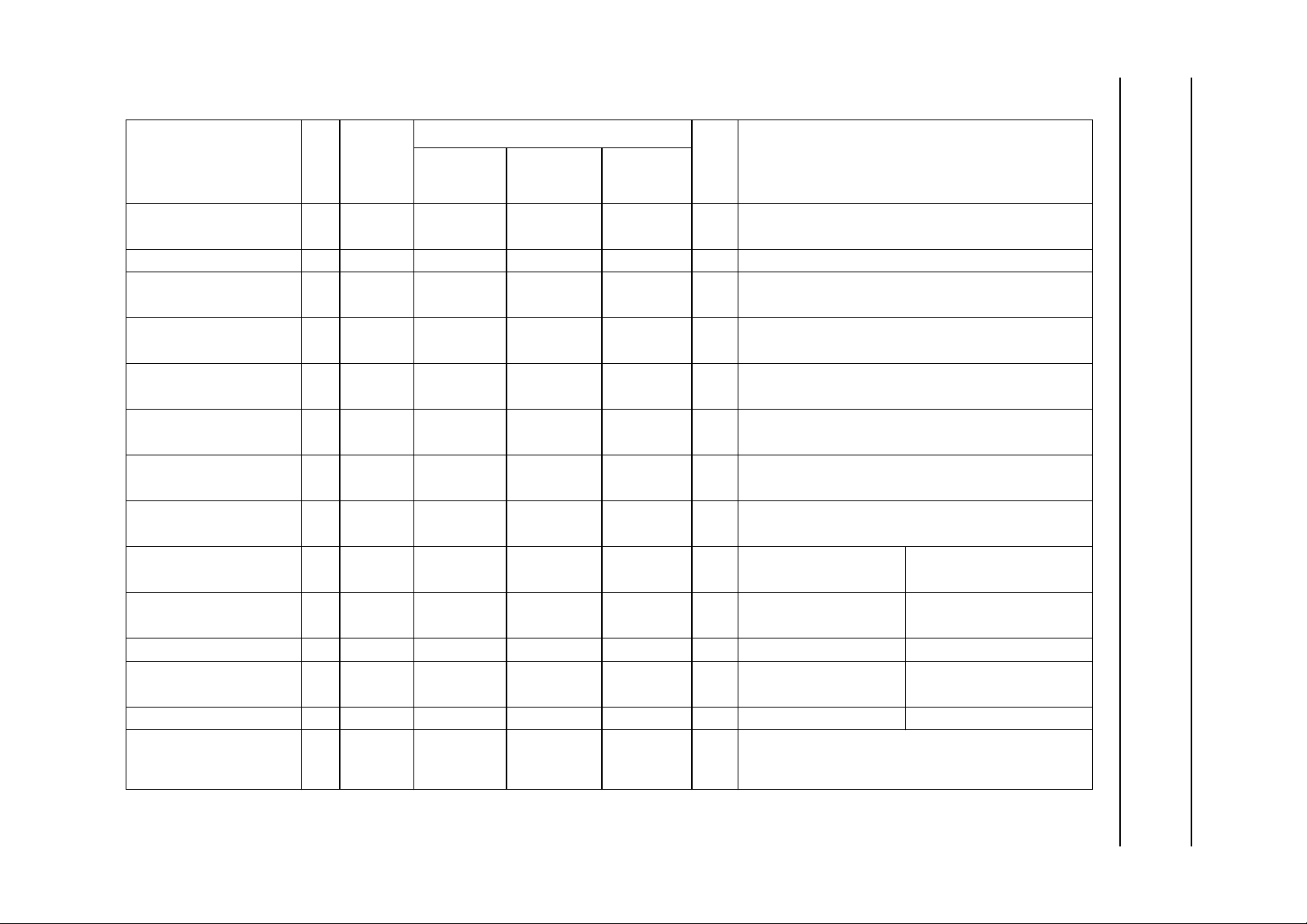
DC CHARACTERISTICS
=0 V
V
SS
T
(°C)
amb
V
DD
PARAMETER
V
SYMBOL
MIN. MAX. MIN. MAX. MIN. MAX.
Quiescent device current
Input leakage current 10 ± I
Input voltage HIGH
Input voltage LOW
Output voltage HIGH
Output voltage LOW
Input tripping level; 5
input voltage increasing 10 3,0 8,0 3,0 8,0 3,0 8,0 V
Input tripping level; 5
input voltage decreasing 10 2,0 7,0 2,0 7,0 2,0 7,0 V
Output current LOW
Output current HIGH 5
Output current HIGH 5 −I
Output current HIGH
Output current HIGH 5 −I
Total supply current 10 I
5
I
DD
10 − 100 − 100 − 750 µAV
IN
5
V
IH
10 7,0 − 7,0 − 7,0 − V
5
V
IL
10 − 3,0 − 3,0 − 3,0 V
5
V
OH
10 9,95 − 9,95 − 9,95 − V
5
V
OL
10 − 0,05 − 0,05 − 0,05 V
V
ti
V
td
5
I
OL
10 1,4 − 1,17 − 0,9 − mA V
−I
OH
10 0,9 − 0,75 − 0,6 − mA V
OH
5
−I
OH
10 1,8 − 1,5 − 1,2 − mA V
OH
tot
− 50 − 50 − 375 µA all valid input combinations;
−−−0,3 − 1 µAV
3,5 − 3,5 − 3,5 − V
− 1,5 − 1,5 − 1,5 V
4,95 − 4,95 − 4,95 − V
− 0,05 − 0,05 − 0,05 V
1,5 4,0 1,5 4,0 1,5 4,0 V
1,0 3,5 1,0 3,5 1,0 3,5 V
0,45 − 0,38 − 0,3 − mA VOL= 0,4 V
0,3 − 0,25 − 0,2 − mA VOH= 4,6 V
0,9 − 0,75 − 0,6 − mA VOH= 2,5 V outputs: group I
0,6 − 0,5 − 0,4 − mA VOH= 4,6 V
1,8 − 1,5 − 1,2 − mA VOH= 2,5 V outputs: group II
−−typ. 2 −−−mA
Philips Semiconductors Product specification
A.C. motor control circuit
UNIT CONDITIONS−40 + 25 + 85
I=VSS
I
or V
= 0 or 10 V
DD
inputs: group I
inputs: group I
V
I=VSS
V
I=VSS
or VDD; IO<1µA
or VDD; IO<1µA
inputs: group II
inputs: group II
OL
OH
OH
= 0,5 V
= 9,5 V
= 9,5 V
outputs: groups I and II
outputs: group I
outputs: groups II
HEF4752V
IOL=IOH= 0; frequency applied to
inputs; FCT = 700 kHz; VCT = 400 kHz;
RCT = 400 kHz
LSI
Page 5
Philips Semiconductors Product specification
A.C. motor control circuit
APPLICATION INFORMATION
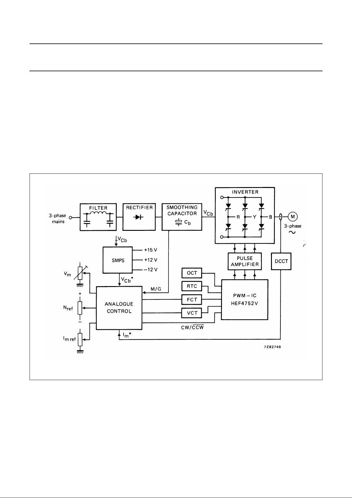
Figure 2 shows the functional block diagram of a 3-phase
a.c. motor speed control system using a thyristorized
inverter with variable frequency output. The inverter
control signals are generated by the HEF4752V
(PWM-IC). A special feature of the PWM (Pulse-Width
Modulation) - IC is here, that the motor is supplied by
sinoidally modulated pulses, hence the resulting motor
current will approach a sine-wave with a minimum on
higher harmonics. In this way, an optimum speed drive
with high performance is obtained.
HEF4752V
LSI
Furthermore, the HEF4752V contains all logic circuitry
required for this special waveform generation, so that the
amount of control circuit components is reduced
considerable. The speed drive system in Fig.2 is controlled
by the analogue control section.
The FCT and VCT clock pulse oscillators are driven in
such a way, that a fast response speed control of the a.c.
motor is obtained, depending on: the reference values for
speed; motor voltage; motor current (Limited by the
measured motor current via DCCT - d.c. current
transformer -); the increasing value of V
action.
during braking
Cb
Fig.2 PWM motor speed control system using HEF4752V.
January 1995 5
Page 6
January 1995 6
Philips Semiconductors Product specification
A.C. motor control circuit
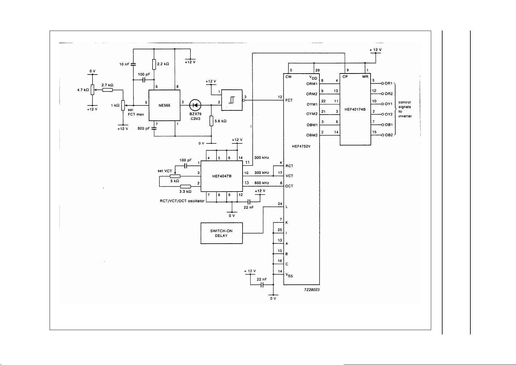
Fig.3 Application of HEF4752V in a basic circuit configuration for AC motor control.
HEF4752V
LSI
 Loading...