

Page 1

DATA SH EET
Product specification
File under Integrated Circuits, IC04
January 1995
INTEGRATED CIRCUITS
HEF4541B
MSI
Programmable timer
For a complete data sheet, please also download:
•The IC04 LOCMOS HE4000B Logic
Family Specifications HEF, HEC
•The IC04 LOCMOS HE4000B Logic
Package Outlines/Information HEF, HEC
Page 2
January 1995 2
Philips Semiconductors Product specification
Programmable timer
HEF4541B
MSI
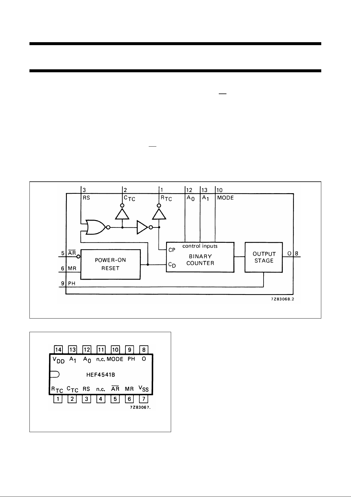
DESCRIPTION
The HEF4541B is a programmable timer which consists of
a 16-stage binary counter, an integrated oscillator to be
used with external timing components, an automatic
power-on reset and output control logic. The frequency of
the oscillator is determined by the external components
Rtand Ctwithin the frequency range 1 Hz to 100 kHz. This
oscillator may be replaced by an external clock signal at
input RS, the timer advances on the positive-going
transition of RS. A LOW on the auto reset input (AR) and
a LOW on the master reset input (MR) enables the internal
power-on reset. A HIGH level at input MR resets the
counter independent on all other inputs. Resetting
disables the oscillator to provide no active power
dissipation.
A HIGH at input
AR turns off the power-on reset to provide
a low quiescent power dissipation of the timer. The
16-stage counter divides the oscillator frequency by
28,210,213or 216depending on the state of the address
inputs (A0,A1). The divided oscillator frequency is
available at output O. The phase input (PH) features a
complementary output signal. If the mode select input
(MODE) is LOW or HIGH the timer can be used
respectively as a single transition timer or 2nfrequency
divider.
Fig.1 Functional diagram.
Fig.2 Pinning diagram.
FAMILY DATA, IDDLIMITS category MSI
See Family Specifications
HEF4541BP(N): 14-lead DIL; plastic
(SOT27-1)
HEF4541BD(F): 14-lead DIL; ceramic (cerdip)
(SOT73)
HEF4541BT(D): 14-lead SO; plastic
(SOT108-1)
( ): Package Designator North America
Page 3
January 1995 3
Philips Semiconductors Product specification
Programmable timer
HEF4541B
MSI
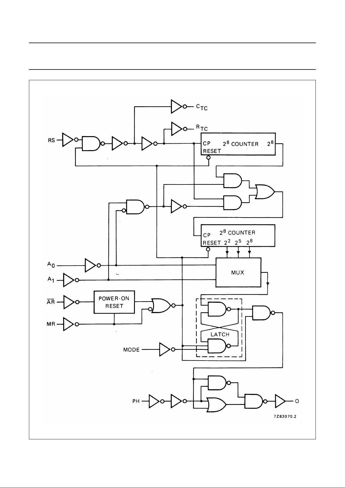
Fig.3 Logic diagram.
Page 4

January 1995 4
Philips Semiconductors Product specification
Programmable timer
HEF4541B
MSI
PINNING
FREQUENCY SELECTION TABLE
A
0,A1
address inputs
MODE mode select input
AR auto reset input
MR master reset input
PH phase input
R
TC
external resistor connection (Rt)
C
TC
external capacitor connection (Ct)
RS external resistor connection (R
S
)or
external clock input
A
0
A
1
NUMBER OF
COUNTER STAGES n
L L 13 8 192
L H 10 1 024
H L 8 256
H H 16 65 536
f
osc
f
out
--------- 2n=
FUNCTION TABLE
Notes
1. For correct power-on reset, the supply voltage should
be above 8.5 V. For V
DD
< 8.5 V, disable the autoreset
and connect AR to VDD.
2. The timer is initialized on a reset pulse and the output
changes state after 2
n-1
counts and remains in that
state (latched). Reset of this latch is obtained by
master reset or by a LOW to HIGH transition on the
MODE input.
H = HIGH state (the more positive voltage)
L = LOW state (the less positive voltage)
X = state is immaterial
INPUTS
MODE
AR MR PH MODE
H L X X auto reset disabled
L L X X auto reset enabled
(1)
X H X X master reset active
X L X H normal operation selected
division to output
X L X L single-cycle mode
(2)
X L L X output initially LOW,
after reset
X L H X output initially HIGH,
after reset
RC oscillator
Fig.4 External component connection for RC
oscillator; RS≈ 2 Rt.
Typical formula for oscillator
frequency:
f
osc
1
23 RtCt××,
---------------------------------=
Timing component limitations
The oscillator frequency is mainly determined by
RtCt, provided Rt << RSand RSC2 << RtCt. The function of
RSis to minimize the influence of the forward voltage
across the input protection diodes on the frequency. The
stray capacitance C2 should be kept as small as possible.
In consideration of accuracy, Ctmust be larger than the
inherent stray capacitance. Rtmust be larger than the
LOCMOS ‘ON’ resistance in series with it, which typically
is 500 Ω at VDD= 5 V, 300 Ω at VDD= 10 V and 200 Ω at
V
DD
= 15 V.
The recommended values for these components to
maintain agreement with the typical oscillation formula are:
Ct≥ 100 pF, up to any typical value,
10 kΩ≤Rt≤1MΩ.
Page 5

January 1995 5
Philips Semiconductors Product specification
Programmable timer
HEF4541B
MSI
Fig.5 RC oscillator frequency as a function of Rtand Ctat VDD= 5 to 15 V; T
amb
=25°C.
Ctcurve at Rt= 56 kΩ;RS= 120 kΩ.
−−− R
t
curve at Ct= 1 nF; RS=2 Rt.
Page 6

January 1995 6
Philips Semiconductors Product specification
Programmable timer
HEF4541B
MSI
Fig.6 Frequency deviation (∆f) as a function of ambient temperature; referenced at : f
osc
at T
amb
=25°C and
VDD= 10 V.
Rt= 56 kΩ;Ct= 1 nF; RS=0.
−−−R
t
= 56 kΩ; Ct= 1 nF; RS= 120 kΩ.
Page 7

January 1995 7
Philips Semiconductors Product specification
Programmable timer
HEF4541B
MSI
DC CHARACTERISTICS
V
SS
=0 V
Note
1. All inputs at 0 V or V
DD
; except input AR = input MR = 0 V (power-on reset active).
AC CHARACTERISTICS
V
SS
= 0 V; T
amb
=25°C; input transition times ≤ 20 ns
Notes
1. where:
f
i
= input frequency (MHz)
fo= output frequency (MHz)
CL= load capacitance (pF)
VDD= supply voltage (V)
Ct= timing capacitance (pF)
f
osc
= oscillator frequency (MHz)
V
DD
V
V
OL
V
V
OH
V
SYMBOL
T
amb
(°C)
−40 + 25 + 85
MIN. MAX. MIN. TYP. MAX. MIN. MAX.
Supply current 5 − 80 − 20 80 − 230 µA
power-on reset 10 I
D
− 750 − 250 600 − 700 µA
enabled (note) 15 − 1600 − 500 1300 − 1500 µA
Supply voltage for automatic
reset initialization (note) V
DD
−−8,5 5 −− −V
Output current 5 4,6 0,5 − 0,4 −− 0,3 − mA
HIGH; CTC,R
TC
10 9,5 −I
OH
1,4 − 1,2 −− 0,95 − mA
15 13,5 4,8 − 4,0 −− 3,2 − mA
5 2,5 −I
OH
1,4 − 1,2 −− 0,95 − mA
Output current 5 0,4 0,33 − 0,27 −− 0,20 − mA
LOW; C
TC,RTC
10 0,5 I
OL
1,00 − 0,85 −− 0,68 − mA
15 1,5 3,20 − 2,70 −− 2,30 − mA
V
DD
V
TYPICAL FORMULA FOR P (µW)
(1)
Dynamic power dissipation 5 1 300 fi+ foCLV
DD
2
per package 10 5 300 fi+ foCLV
DD
2
(P) 15 12 000 fi+ foCLV
DD
2
Total power dissipation 5 1 300 f
osc
+ foCLV
DD
2
+ 2CtV
DD
2
f
osc
+ 10 V
DD
when using the 10 5 300 f
osc
+ foCLV
DD
2
+ 2CtV
DD
2
f
osc
+ 100 V
DD
on-chip oscillator (P) 15 12 000 f
osc
+ foCLV
DD
2
+ 2CtV
DD
2
f
osc
+ 400 V
DD
Page 8

January 1995 8
Philips Semiconductors Product specification
Programmable timer
HEF4541B
MSI
AC CHARACTERISTICS
V
SS
= 0 V; T
amb
=25°C; CL= 50 pF; input transition times ≤ 20 ns
V
DD
V
SYMBOL MIN. TYP. MAX.
TYPICAL EXTRAPOLATION
FORMULA
Propagation delays
RS → O
2
8
selected 5
t
PHL
;
t
PLH
375 750 ns 348 ns + (0,55 ns/pF) C
L
HIGH to LOW
LOW to HIGH
10 150 300 ns 139 ns + (0,23 ns/pF) C
L
15 110 220 ns 102 ns + (0,16 ns/pF) C
L
RS → O
2
10
selected 5
t
PHL
;
t
PLH
425 850 ns 398 ns + (0,55 ns/pF) C
L
HIGH to LOW
LOW to HIGH
10 165 330 ns 154 ns + (0,23 ns/pF) C
L
15 120 240 ns 112 ns + (0,16 ns/pF) C
L
RS → O
2
13
selected 5
t
PHL
;
t
PLH
510 1020 ns 483 ns + (0,55 ns/pF) C
L
HIGH to LOW
LOW to HIGH
10 190 380 ns 179 ns + (0,23 ns/pF) C
L
15 135 270 ns 127 ns + (0,16 ns/pF) C
L
RS → O
2
16
selected 5
t
PHL
;
t
PLH
575 1150 ns 548 ns + (0,55 ns/pF) C
L
HIGH to LOW
LOW to HIGH
10 210 420 ns 199 ns + (0,23 ns/pF) C
L
15 150 300 ns 142 ns + (0,16 ns/pF) C
L
Minimum clock 5 60 30 ns
pulse width; LOW 10 t
WRSL
30 15 ns
15 24 12 ns
Minimum reset 5 60 30 ns
pulse width; HIGH 10 t
WMRH
30 15 ns
15 24 12 ns
Maximum clock 5 8 16 MHz
pulse frequency 10 f
max
15 30 MHz
15 18 36 MHz
Oscillator frequency 5 90 kHz R
t
=5 kΩ
10 f
osc
90 kHz Ct= 1 nF
15 90 kHz R
S
= 10 kΩ
Oscillator frequency 5 8 kHz R
t
= 56 kΩ
10 f
osc
8 kHz Ct= 1 nF
15 8 kHz R
S
= 120 kΩ
 Loading...