

Page 1

HEF4013B
Dual D-type flip-flop
Rev. 8 — 21 November 2011 Product data sheet
1. General description
The HEF4013B is a dual D-type flip-flop that features independent set-direct input (SD),
clear-direct input (CD), clock input (CP) and outputs (Q, Q
LOW and is transferred to the output on the positive-going edge of the clock. The active
HIGH asynchronous CD and SD inputs are independent and override the D or CP inputs.
The outputs are buffered for best system performance. The clock inp ut ’s Schmitt-trig ge r
action makes the circuit highly tolerant of slower clock rise and fall times.
). Data is accepted when CP is
It operates over a recommended V
(usually ground). Unused inputs must be connected to V
power supply range of 3 V to 15 V referenced to VSS
DD
, VSS, or another input.
DD
2. Features and benefits
Tolerant of slow clock rise and fall times
Fully static operation
5 V, 10 V, and 15 V parametric ratings
Standardized symmetrical output characteristics
Specifie d from 40 C to +125 C
Complies with JEDEC standard JESD 13-B
3. Applications
Counters and dividers
Registers
Toggle flip-flops
4. Ordering information
Table 1. Ordering information
All types operate from
Type number Package
HEF4013BP DIP14 plastic dual in-line package; 14 leads (300 mil) SOT27-1
HEF4013BT SO14 plastic small outline package; 14 leads; body width 3.9 mm SOT108-1
HEF4013BTT TSSOP14 plastic thin shrink small outline package; 14 leads; body width 4.4 mm SOT402-1
40
C to +125C
Name Description Version
Page 2
NXP Semiconductors
001aag084
1SD
1D
1CP
1CD
2SD
2D
2Q
2Q
1Q
1Q
13
12
1
2
2CP
2CD
6
5
3
4
8
9
11
10
SD
CD
DQ
FF1
CP
Q
SD
CD
DQ
FF2
CP
Q
D
SD
CD
CP
C
C
001aag086
C
C
C
C
C
C
C
C
Q
Q
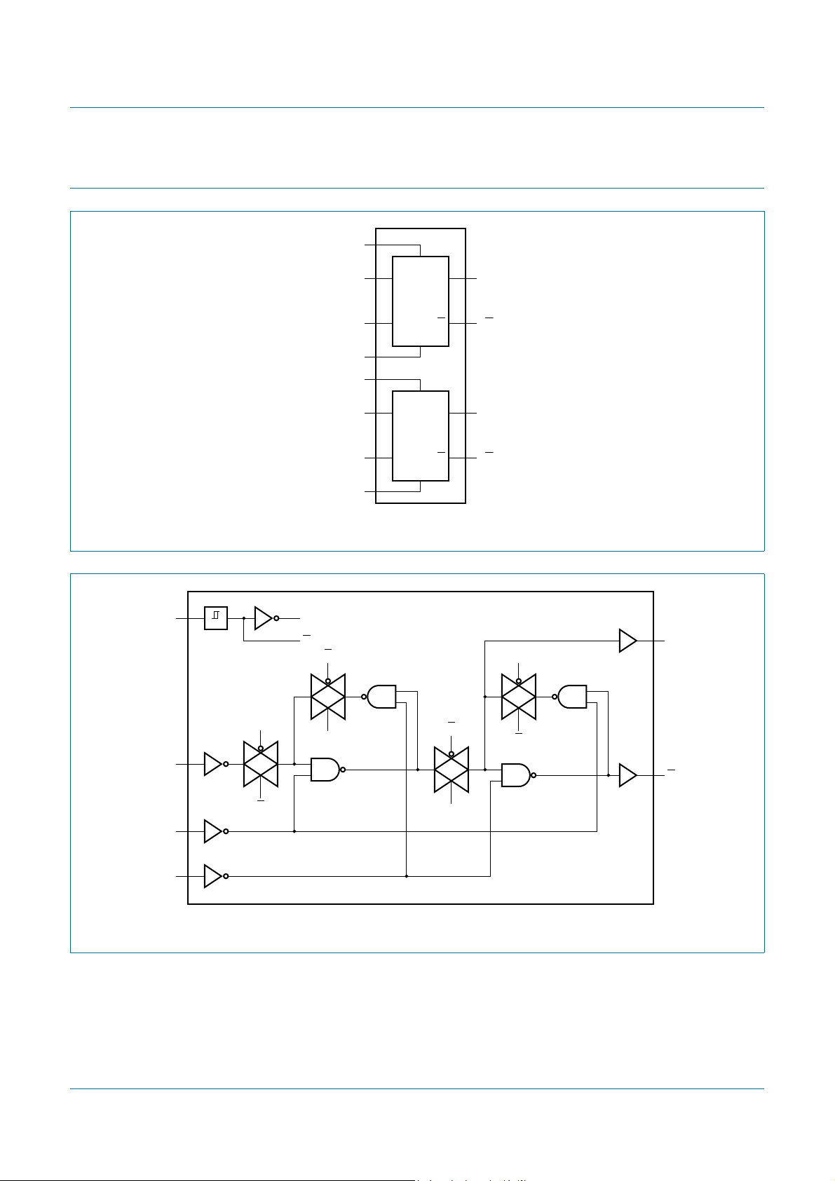
5. Functional diagram
HEF4013B
Dual D-type flip-flop
Fig 1. Functional diagram
Fig 2. Logic diagram (one flip-flop)
HEF4013B All information provided in this document is subject to legal disclaimers. © NXP B.V. 2011. All rights reserved.
Product data sheet Rev. 8 — 21 November 2011 2 of 16
Page 3
NXP Semiconductors
HEF4013B
1Q V
DD
1Q 2Q
1CP 2Q
1CD 2CP
1D 2CD
1SD 2D
V
SS
2SD
001aag085
1
2
3
4
5
6
7 8
10
9
12
11
14
13
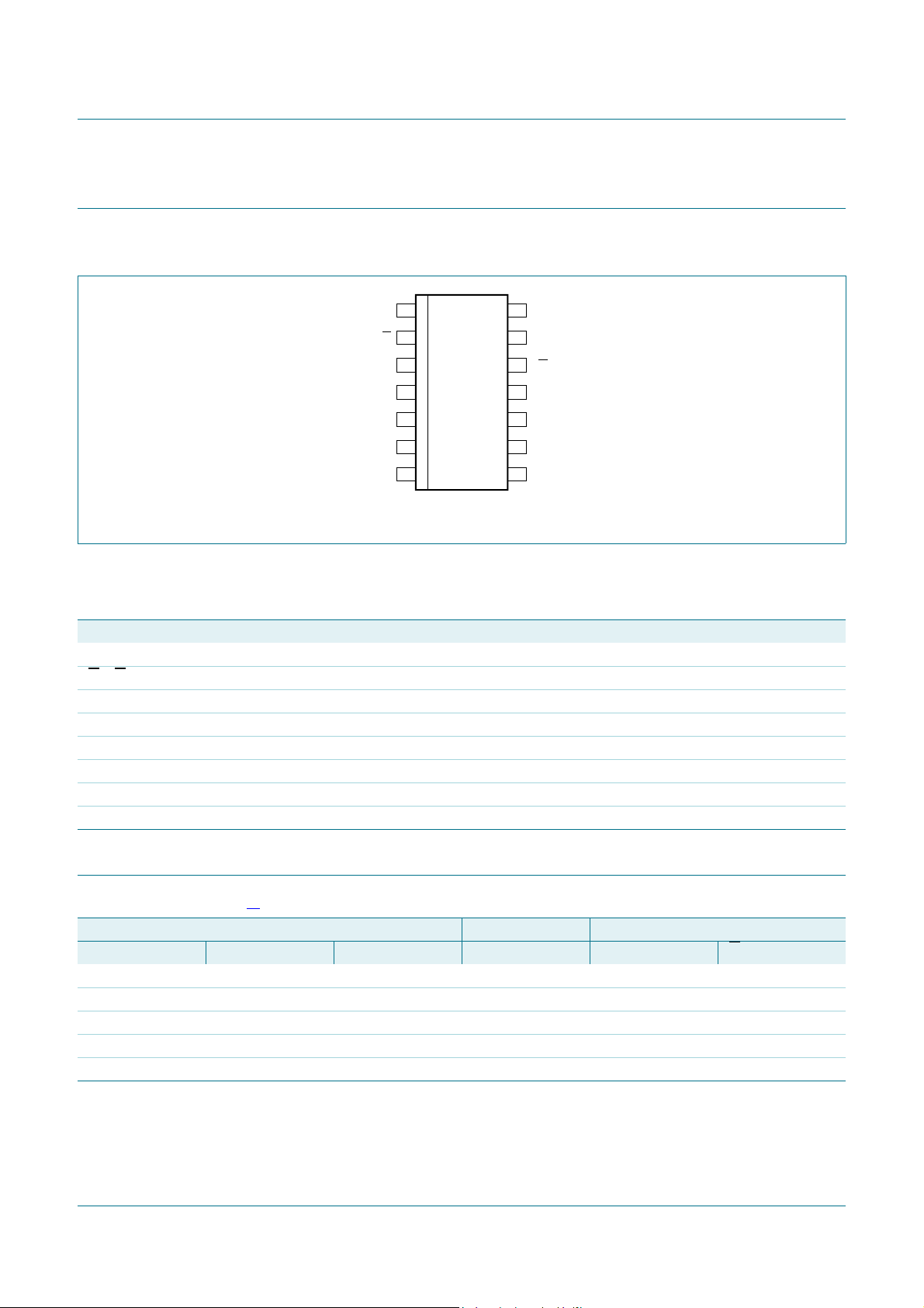
6. Pinning information
6.1 Pinning
Fig 3. Pin configuration
HEF4013B
Dual D-type flip-flop
6.2 Pin description
Table 2. Pin description
Symbol Pin Description
1Q, 2Q 1, 13 true output
, 2Q 2, 12 complement output
1Q
1CP, 2CP 3, 11 clock input (LOW to HIGH edge-triggered)
1CD, 2CD 4, 10 asynchronous clear-direct input (active HIGH)
1D, 2D 5, 9 data input
1SD, 2SD 6, 8 asynchronous set-direct input (active HIGH)
V
SS
V
DD
7 ground (0 V)
14 supply voltage
7. Functional description
Table 3. Function table
Control Input Output
nSD nCD nCP nD nQ nQ
HLXXHL
LHXXLH
HHXXHH
LL LLH
LL HHL
[1]
[1] H = HIGH voltage level; L = LOW voltage level; X = don’t care; = LOW-to-HIGH clock transition.
HEF4013B All information provided in this document is subject to legal disclaimers. © NXP B.V. 2011. All rights reserved.
Product data sheet Rev. 8 — 21 November 2011 3 of 16
Page 4

NXP Semiconductors
8. Limiting values
HEF4013B
Dual D-type flip-flop
Table 4. Limiting values
In accordance with the Absolute Maximum Rating System (IEC 60134). Voltages are referenced to VSS= 0 V (ground).
Symbol Parameter Conditions Min Max Unit
V
DD
I
IK
V
I
I
OK
I
I/O
I
DD
T
stg
T
amb
P
tot
supply voltage 0.5 +18 V
input clamping current VI< 0.5 V or VI>VDD + 0.5 V - 10 mA
input voltage 0.5 VDD + 0.5 V
output clamping current VO< 0.5 V or VO>VDD + 0.5 V - 10 mA
input/output current - 10 mA
supply current - 50 mA
storage temperature 65 +150 C
ambient temperature 40 +125 C
total power dissipation T
= 40 C to +125 C
amb
DIP14
SO14
TSSOP14
[1]
- 750 mW
[2]
- 500 mW
[3]
- 500 mW
P power dissipation per output - 100 mW
[1] For DIP14 packages: above T
[2] For SO14 packages: above T
[3] For TSSOP14 packages: above T
= 70 C, P
amb
= 70 C, P
amb
amb
tot
derates linearly with 8 mW/K.
tot
= 60 C, P
derates linearly with 12 mW/K.
derates linearly with 5.5 mW/K.
tot
9. Recommended operating conditions
Table 5. Recommended operating conditions
Symbol Parameter Conditions Min Max Unit
V
DD
V
I
T
amb
supply voltage 3 15 V
input voltage 0 V
ambient temperature 40 +125 C
t/V input transition rise and fall rate V
DD
= 5 V - 3.75 s/V
DD
= 10 V - 0.5 s/V
V
DD
= 15 V - 0.08 s/V
V
DD
V
HEF4013B All information provided in this document is subject to legal disclaimers. © NXP B.V. 2011. All rights reserved.
Product data sheet Rev. 8 — 21 November 2011 4 of 16
Page 5

NXP Semiconductors
10. Static characteristics
HEF4013B
Dual D-type flip-flop
Table 6. Static characteristics
VSS = 0 V; VI=VSS or VDD; unless otherwise specified.
Symbol Parameter Conditions V
V
IH
HIGH-level
IO < 1 A 5 V 3.5 - 3.5 - 3.5 - 3.5 - V
input voltage
DD
10 V 7.0 - 7.0 - 7.0 - 7.0 - V
15 V 11.0 - 11.0 - 11.0 - 11.0 - V
V
IL
LOW-level
input voltage
IO < 1 A 5 V - 1.5 - 1.5 - 1.5 - 1.5 V
10 V - 3.0 - 3.0 - 3.0 - 3.0 V
15 V - 4.0 - 4.0 - 4.0 - 4.0 V
V
OH
HIGH-level
output voltage
IO < 1 A 5 V 4.95 - 4.95 - 4.95 - 4.95 - V
10 V 9.95 - 9.95 - 9.95 - 9.95 - V
15 V 14.95 - 14.95 - 14.95 - 14.95 - V
V
OL
LOW-level
output voltage
IO < 1 A 5 V - 0.05 - 0.05 - 0.05 - 0.05 V
10 V - 0.05 - 0.05 - 0.05 - 0.05 V
15 V - 0.05 - 0.05 - 0.05 - 0.05 V
I
OH
HIGH-level
output current
I
OL
LOW-level
output current
I
I
input leakage
VO = 2.5V 5V - 1.7 - 1.4 - 1.1 - 1.1 mA
= 4.6 V 5 V - 0.64 - 0.5 - 0.36 - 0.36 mA
V
O
= 9.5 V 10 V - 1.6 - 1.3 - 0.9 - 0.9 mA
V
O
V
= 13.5 V 15 V - 4.2 - 3.4 - 2.4 - 2.4 mA
O
VO = 0.4 V 5 V 0.64 - 0.5 - 0.36 - 0.36 - mA
= 0.5 V 10 V 1.6 - 1.3 - 0.9 - 0.9 - mA
V
O
= 1.5 V 15 V 4.2 - 3.4 - 2.4 - 2.4 - mA
V
O
15 V - 0.1 - 0.1 - 1.0 - 1.0 A
current
I
DD
supply current all valid input
combinations;
=0 A
I
O
C
I
input
5 V - 1.0 - 1.0 - 30 - 30 A
10 V - 2.0 - 2.0 - 60 - 60 A
15 V - 4.0 - 4.0 - 120 - 120 A
- ---7.5--- -pF
capacitance
T
= 40 C T
amb
= +25 C T
amb
= +85 C T
amb
= +125 C Unit
amb
Min Max Min Max Min Max Min Max
HEF4013B All information provided in this document is subject to legal disclaimers. © NXP B.V. 2011. All rights reserved.
Product data sheet Rev. 8 — 21 November 2011 5 of 16
Page 6
NXP Semiconductors
11. Dynamic characteristics
HEF4013B
Dual D-type flip-flop
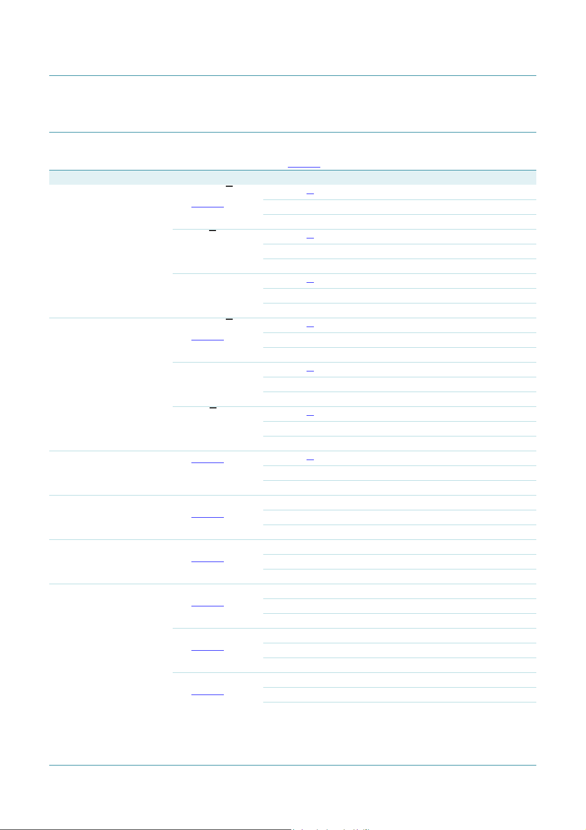
Table 7. Dynamic characteristics
T
= 25 C; unless otherwise specified. For test circuit see Figure 6.
amb
Symbol Parameter Conditions V
t
PHL
HIGH to LOW
propagation delay
nCP to nQ, nQ;
see Figure 4
DD
5 V
10 V 34 + 0.23 C
15 V 22 + 0.16 C
nSD to nQ
5 V
10 V 29 + 0.23 C
15 V 22 + 0.16 C
nCD to nQ 5 V
10 V 29 + 0.23 C
15 V 22 + 0.16 C
t
PLH
LOW to HIGH
propagation delay
nCP to nQ, nQ;
see Figure 4
5 V
10 V 29 + 0.23 C
15 V 22 + 0.16 C
nSD to nQ 5 V
10 V 24 + 0.23 C
15 V 17 + 0.16 C
nCD to nQ
5 V
10 V 19 + 0.23 C
15 V 12 + 0.16 C
t
t
transition time see Figure 4 5 V
10 V 9 + 0.42 C
15 V 6 + 0.28 C
t
su
set-up time nD to nCP;
see Figure 4
5 V 40 20 - ns
10 V 25 10 - ns
15 V 15 5 - ns
t
h
hold time nD to nCP;
see Figure 4
5 V 20 0 - ns
10 V 20 0 - ns
15 V 15 0 - ns
t
W
pulse width nCP input LOW;
see Figure 4
5 V 60 30 - ns
10 V 30 15 - ns
15 V 20 10 - ns
nSD input HIGH;
see Figure 5
5 V 50 25 - ns
10 V 24 12 - ns
15 V 20 10 - ns
nCD input HIGH;
see Figure 5
5 V 50 25 - ns
10 V 24 12 - ns
15 V 20 10 - ns
Extrapolation formula Min Typ Max Unit
[1]
83 + 0.55 C
[1]
73 + 0.55 C
[1]
73 + 0.55 C
[1]
68 + 0.55 C
[1]
48 + 0.55 C
[1]
33 + 0.55 C
[1]
10 + 1.00 C
L
L
L
L
L
L
L
L
L
L
L
L
L
L
L
L
L
L
L
L
L
- 110 220 ns
- 4590ns
- 3060ns
- 100 200 ns
- 4080ns
- 3060ns
- 100 200 ns
- 4080ns
- 3060ns
-95190ns
- 4080ns
- 3060ns
-75150ns
- 3570ns
- 2550ns
-60120ns
- 3060ns
- 2040ns
-60120ns
- 3060ns
- 2040ns
HEF4013B All information provided in this document is subject to legal disclaimers. © NXP B.V. 2011. All rights reserved.
Product data sheet Rev. 8 — 21 November 2011 6 of 16
Page 7
NXP Semiconductors
001aah016
0 V
0 V
t
h
t
su
1/f
clk(max)
t
h
t
su
t
f
t
r
t
W
V
M
V
M
V
M
V
I
V
OH
V
OL
V
I
output nQ
input nCP
input nD
t
t
t
t
t
PHL
t
PLH
V
Y
V
X
HEF4013B
Dual D-type flip-flop
Table 7. Dynamic characteristics
T
= 25 C; unless otherwise specified. For test circuit see Figure 6.
amb
Symbol Parameter Conditions V
t
rec
recovery time nSD input;
…continued
see Figure 5
DD
Extrapolation formula Min Typ Max Unit
5 V +15 5- ns
10 V 15 0 - ns
15 V 15 0 - ns
nCD input;
see Figure 5
5 V 40 25 - ns
10 V 25 10 - ns
15 V 25 10 - ns
f
clk(max)
maximum clock
frequency
see Figure 4 5 V 7 14 - MHz
10 V 14 28 - MHz
15 V 20 40 - MHz
[1] Typical values of the propagation delays and output transition times can be calculated with the extrapolation formulas. CL is given in pF.
Table 8. Dynamic power dissipation
= 0 V; tr = tf 20 ns; T
V
SS
amb
= 25 C.
Symbol Parameter VDDTypical formula Where
P
D
dynamic power dissipation 5 V PD = 850 fi + (fo CL) V
10 V P
15 V P
= 3600 fi + (fo CL) V
D
= 9000 fi + (fo CL) V
D
2
Wfi = input frequency in MHz;
DD
2
f
= output frequency in MHz;
W
2
W
o
C
= output load capacitance in pF;
L
DD
DD
(fo CL) = sum of the outputs;
V
= supply voltage in V.
DD
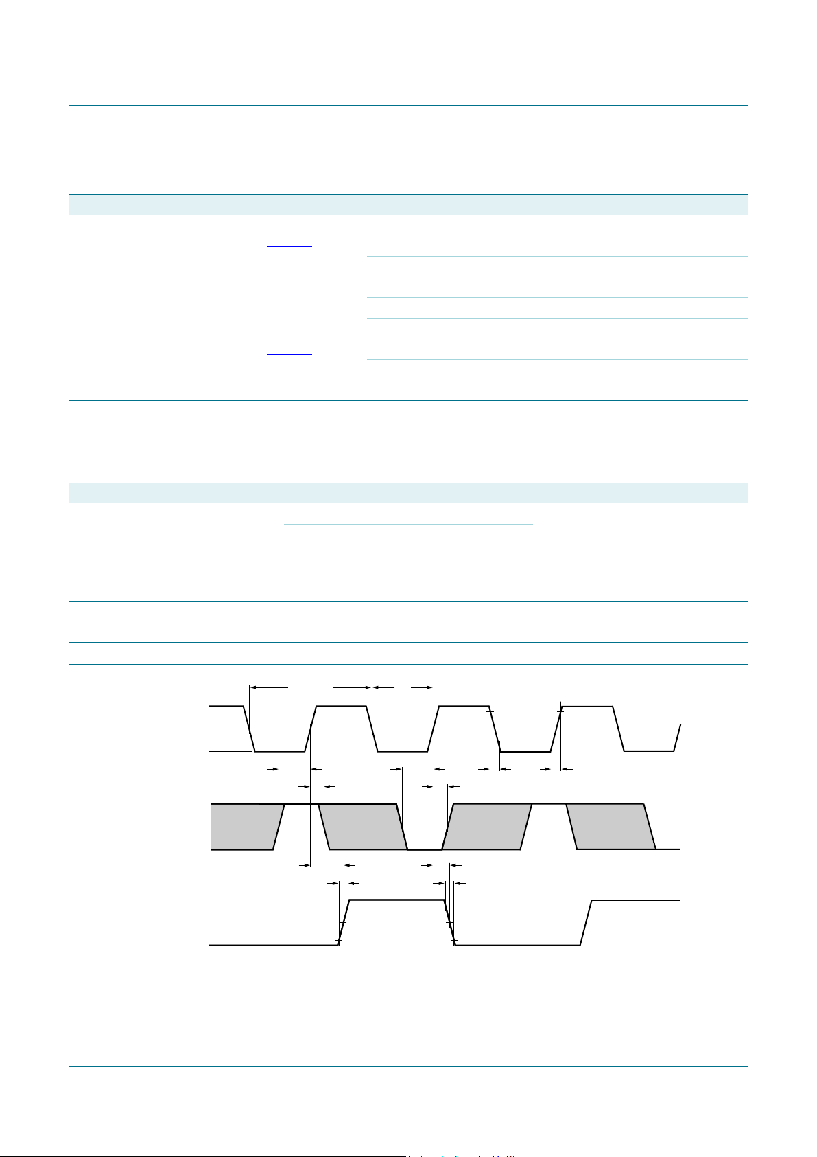
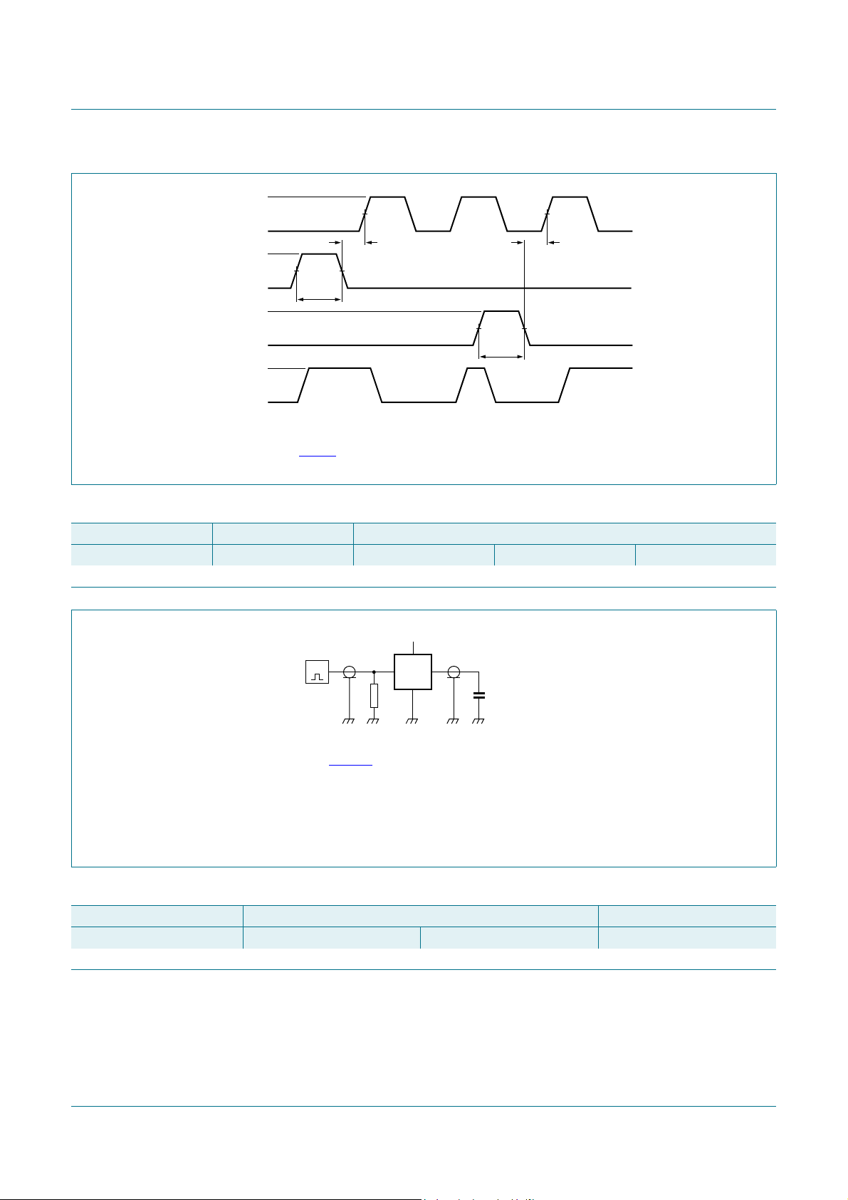
12. Waveforms
Set-up and hold times are shown as positive values but may be specified as negative values.
The shaded areas indicate when the input is permitted to change for predictable output performance.
Measurement points are given in Table 9
Fig 4. Set-up time, hold time, minimum clock pulse width, propagation de la y s an d tra n sition times
HEF4013B All information provided in this document is subject to legal disclaimers. © NXP B.V. 2011. All rights reserved.
Product data sheet Rev. 8 — 21 November 2011 7 of 16
.
Page 8
NXP Semiconductors
001aag088
input nSD
input nCD
input nCP
V
I
0 V
0 V
V
OL
0 V
V
I
V
I
V
OH
t
W
V
M
t
W
V
M
V
M
output nQ
t
rec
t
rec
V
DD
V
I
V
O
001aag182
DUT
C
L
R
T
G
Recovery times are shown as positive values but may be specified as negative values.
Measurement points are given in Table 9
Fig 5. nSD, nCD recovery time and pulse width
.
HEF4013B
Dual D-type flip-flop
Table 9. Measurement points
Supply voltage Input Output
V
DD
5 V to 15 V 0.5V
Test and measurement data is given in Table 10;
Definitions test circuit:
DUT = Device Under Test.
= Termination resistance should be equal to output impedance Zo of the pulse generator.
R
T
C
= Load capacitance including jig and probe capacitance.
L
V
M
DD
V
M
0.5V
DD
V
X
0.1V
DD
Fig 6. Test circuit for measuring switching times
Table 10. Test data
Supply voltage Input Load
V
DD
5 V to 15 V VSS or V
V
I
DD
tr, t
f
C
L
20 ns 50 pF
V
Y
0.9V
DD
HEF4013B All information provided in this document is subject to legal disclaimers. © NXP B.V. 2011. All rights reserved.
Product data sheet Rev. 8 — 21 November 2011 8 of 16
Page 9
NXP Semiconductors
001aag089
CP
FF
1
Q
Q
DDQ
clock
CP
FF
2
Q
Q
D
CP
FF
n
Q
Q
D
001aag090
CP
T-type flip-flop
FF
1
Q
Q
DQ
clock
CP
FF
2
Q
Q
D
CP
FF
n
Q
Q
D
001aag091
CP
FF
1
Q
Q
DQ
clock
CP
FF
2
Q
Q
D
CP
FF
n
Q
Q
D
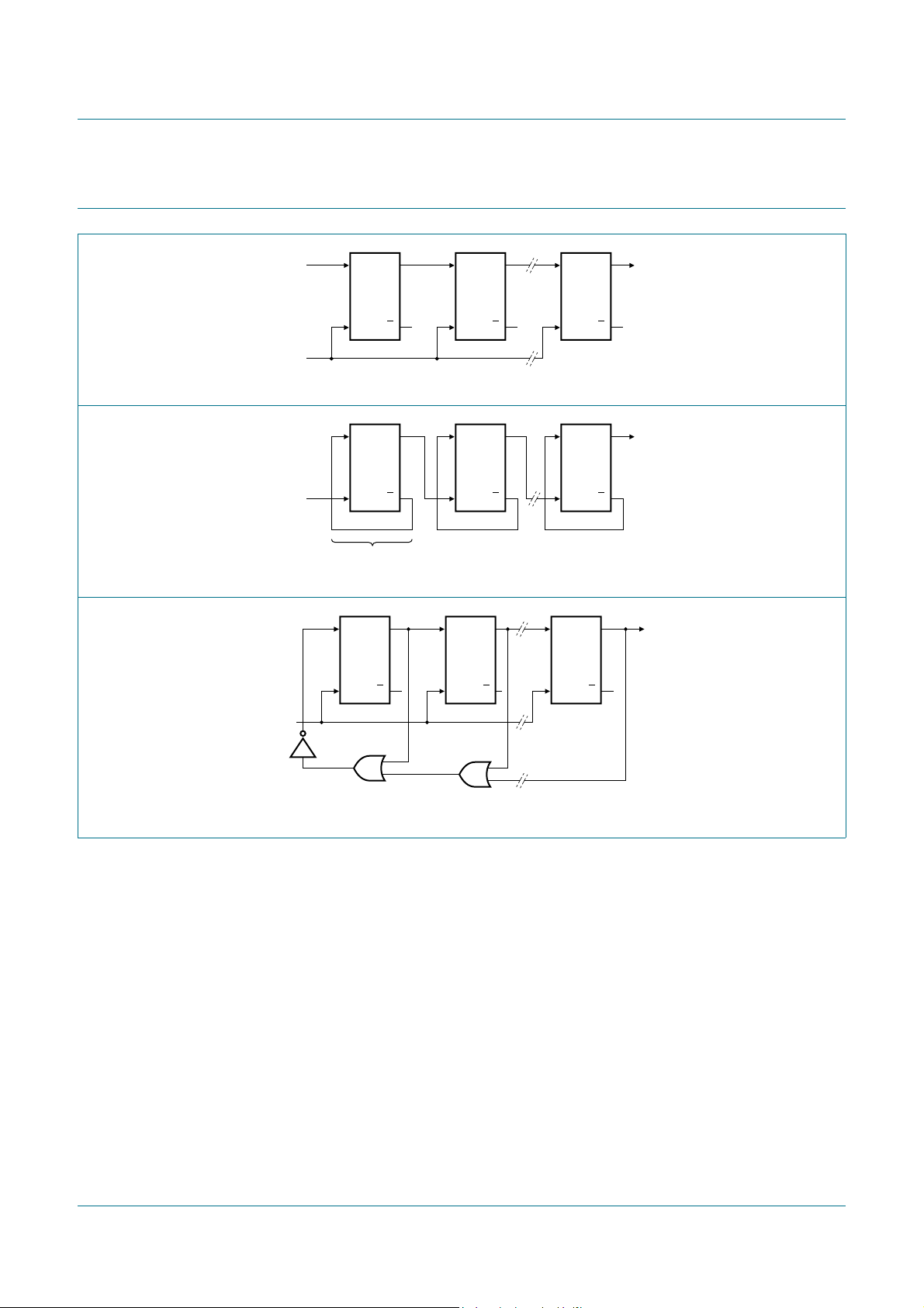
13. Application information
Fig 7. N-stage shift register
HEF4013B
Dual D-type flip-flop
Fig 8. Binary ripple up-counter; divide-by-2
n
Fig 9. Modified ring counter; divide-by-(n + 1)
HEF4013B All information provided in this document is subject to legal disclaimers. © NXP B.V. 2011. All rights reserved.
Product data sheet Rev. 8 — 21 November 2011 9 of 16
Page 10
NXP Semiconductors
UNIT
A
max.
1 2
(1) (1)
b
1
cD
(1)
Z
Ee M
H
L
REFERENCES
OUTLINE
VERSION
EUROPEAN
PROJECTION
ISSUE DATE
IEC JEDEC JEITA
mm
inches
DIMENSIONS (inch dimensions are derived from the original mm dimensions)
SOT27-1
99-12-27
03-02-13
A
min.
A
max.
b
max.
w
M
E
e
1
1.73
1.13
0.53
0.38
0.36
0.23
19.50
18.55
6.48
6.20
3.60
3.05
0.2542.54 7.62
8.25
7.80
10.0
8.3
2.24.2 0.51 3.2
0.068
0.044
0.021
0.015
0.77
0.73
0.014
0.009
0.26
0.24
0.14
0.12
0.010.1 0.3
0.32
0.31
0.39
0.33
0.0870.17 0.02 0.13
050G04 MO-001 SC-501-14
M
H
c
(e )
1
M
E
A
L
seating plane
A
1
w M
b
1
e
D
A
2
Z
14
1
8
7
b
E
pin 1 index
0 5 10 mm
scale
Note
1. Plastic or metal protrusions of 0.25 mm (0.01 inch) maximum per side are not included.
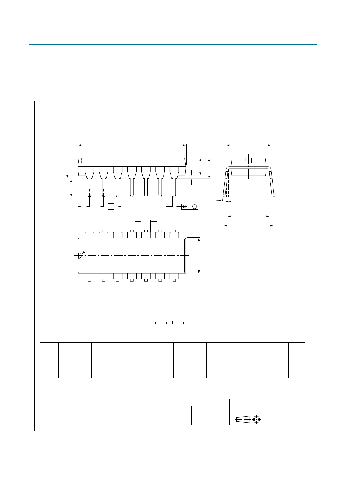
DIP14: plastic dual in-line package; 14 leads (300 mil)
SOT27-1
14. Package outline
HEF4013B
Dual D-type flip-flop
Fig 10. Package outline SOT27-1 (DIP14)
HEF4013B All information provided in this document is subject to legal disclaimers. © NXP B.V. 2011. All rights reserved.
Product data sheet Rev. 8 — 21 November 2011 10 of 16
Page 11
NXP Semiconductors
UNIT
A
max.
A1A2A3b
p
cD
(1)E(1)
(1)
eHELLpQZywv θ
REFERENCES
OUTLINE
VERSION
EUROPEAN
PROJECTION
ISSUE DATE
IEC JEDEC JEITA
mm
inches
1.75
0.25
0.10
1.45
1.25
0.25
0.49
0.36
0.25
0.19
8.75
8.55
4.0
3.8
1.27
6.2
5.8
0.7
0.6
0.7
0.3
8
0
o
o
0.25 0.1
DIMENSIONS (inch dimensions are derived from the original mm dimensions)
Note
1. Plastic or metal protrusions of 0.15 mm (0.006 inch) maximum per side are not included.
1.0
0.4
SOT108-1
X
w M
θ
A
A
1
A
2
b
p
D
H
E
L
p
Q
detail X
E
Z
e
c
L
v M
A
(A )
3
A
7
8
1
14
y
076E06 MS-012
pin 1 index
0.069
0.010
0.004
0.057
0.049
0.01
0.019
0.014
0.0100
0.0075
0.35
0.34
0.16
0.15
0.05
1.05
0.041
0.244
0.228
0.028
0.024
0.028
0.012
0.01
0.25
0.01 0.004
0.039
0.016
99-12-27
03-02-19
0 2.5 5 mm
scale
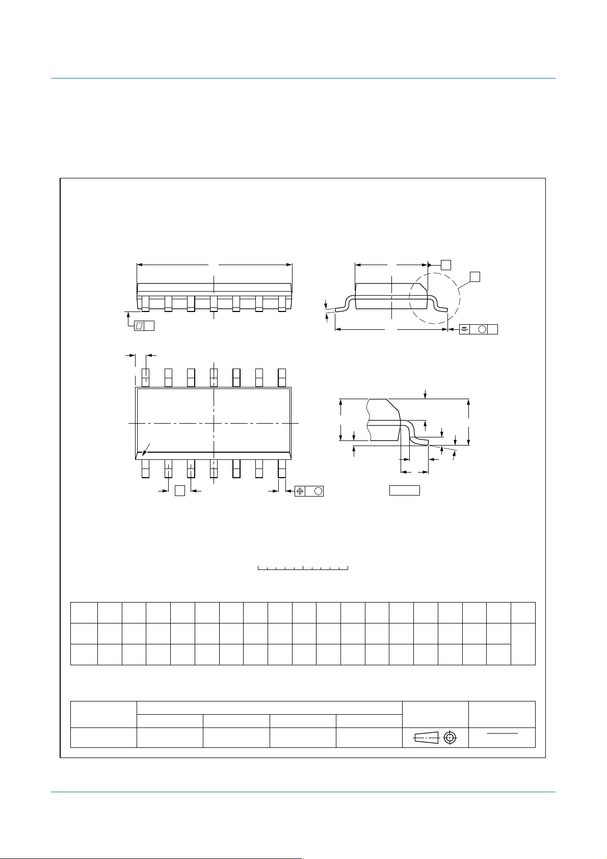
SO14: plastic small outline package; 14 leads; body width 3.9 mm
SOT108-1
HEF4013B
Dual D-type flip-flop
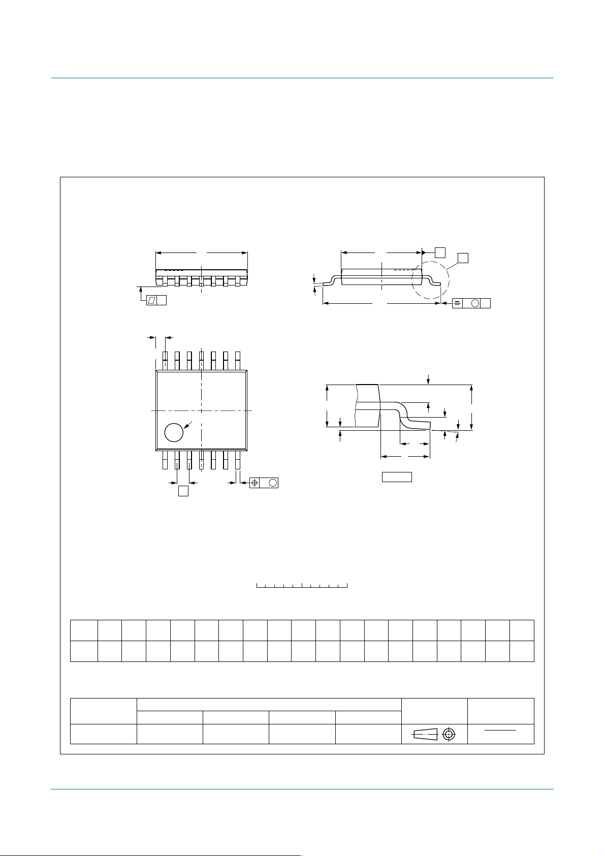
Fig 11. Package outline SOT108-1 (SO14)
HEF4013B All information provided in this document is subject to legal disclaimers. © NXP B.V. 2011. All rights reserved.
Product data sheet Rev. 8 — 21 November 2011 11 of 16
Page 12
NXP Semiconductors
UNIT A1A2A3b
p
cD
(1)E(2) (1)
eHELLpQZywv θ
REFERENCES
OUTLINE
VERSION
EUROPEAN
PROJECTION
ISSUE DATE
IEC JEDEC JEITA
mm
0.15
0.05
0.95
0.80
0.30
0.19
0.2
0.1
5.1
4.9
4.5
4.3
0.65
6.6
6.2
0.4
0.3
0.72
0.38
8
0
o
o
0.13 0.10.21
DIMENSIONS (mm are the original dimensions)
Notes
1. Plastic or metal protrusions of 0.15 mm maximum per side are not included.
2. Plastic interlead protrusions of 0.25 mm maximum per side are not included.
0.75
0.50
SOT402-1 MO-153
99-12-27
03-02-18
w M
b
p
D
Z
e
0.25
17
14
8
θ
A
A
1
A
2
L
p
Q
detail X
L
(A )
3
H
E
E
c
v M
A
X
A
y
0 2.5 5 mm
scale
TSSOP14: plastic thin shrink small outline package; 14 leads; body width 4.4 mm
SOT402-1
A
max.
1.1
pin 1 index
HEF4013B
Dual D-type flip-flop
Fig 12. Package outline SOT402-1 (TSSOP14)
HEF4013B All information provided in this document is subject to legal disclaimers. © NXP B.V. 2011. All rights reserved.
Product data sheet Rev. 8 — 21 November 2011 12 of 16
Page 13

NXP Semiconductors
HEF4013B
Dual D-type flip-flop
15. Revision history
Table 11. Revision history
Document ID Release date Data sheet status Change notice Supersedes
HEF4013B v.8 20111121 Product data sheet - HEF4013B v.7
Modifications:
HEF4013B v.7 20110913 Product data sheet - HEF4013B v.6
HEF4013B v.6 20091027 Product data sheet - HEF4013B v.5
HEF4013B v.5 20090619 Product data sheet - HEF4013B v.4
HEF4013B v.4 20080515 Product data sheet - HEF4013B_CNV v.3
HEF4013B_CNV v.3 19950101 Product specification - HEF4013B_CNV v.2
HEF4013B_CNV v.2 19950101 Product specification - -
• Legal pages updated.
• Changes in “General description”, “Features and benefits” and “Applications”.
HEF4013B All information provided in this document is subject to legal disclaimers. © NXP B.V. 2011. All rights reserved.
Product data sheet Rev. 8 — 21 November 2011 13 of 16
Page 14

NXP Semiconductors
HEF4013B
Dual D-type flip-flop
16. Legal information
16.1 Data sheet status
Document status
Objective [short] data sheet Development This document contains data from the objective specification for product development.
Preliminary [short] data sheet Qualification This document contains data from the preliminary specification.
Product [short] data sheet Production This document contains the product specification.
[1] Please consult the most recently issued document before initiating or completing a design.
[2] The term ‘short data sheet’ is explained in section “Definitions”.
[3] The product status of device(s) d escribed i n this docu ment may have changed si nce this d ocument was p ublished and may dif fer in case of multiple devices. The latest product statu s
information is available on the Internet at URL http://www.nxp.com.
[1][2]
Product status
[3]
Definition
16.2 Definitions
Draft — The document is a draft version only. The content is still under
internal review and subject to formal approval, which may result in
modifications or additions. NXP Semiconductors does not give any
representations or warranties as to the accuracy or completeness of
information included herein and shall have no liability for the consequences of
use of such information.
Short data sheet — A short data sheet is an extract from a full data sheet
with the same product type number(s) and title. A short data sheet is intended
for quick reference only and should not be relied upon to co nt ain det ailed and
full information. For detailed and full information see the relevant full data
sheet, which is available on request via the local NXP Semiconductors sales
office. In case of any inconsistency or conflict with the short data sheet, the
full data sheet shall prevail.
Product specification — The information and data provided in a Product
data sheet shall define the specification of the product as agreed between
NXP Semiconductors and its customer, unless NXP Semiconductors and
customer have explicitly agreed otherwise in writing. In no event however,
shall an agreement be valid in which the NXP Semiconductors product is
deemed to offer functions and qualities beyond those described in the
Product data sheet.
16.3 Disclaimers
Limited warranty and liability — Information in this document is believed to
be accurate and reliable. However, NXP Semiconductors does not give any
representations or warranties, expressed or implied, as to the accuracy or
completeness of such information and shall have no liability for the
consequences of use of such information.
In no event shall NXP Semiconductors be liable for any indirect, incidental,
punitive, special or consequential damages (including - without limitation - lost
profits, lost savings, business interruption, costs related to the removal or
replacement of any products or rework charges) whether or not such
damages are based on tort (including negligence), warranty, breach of
contract or any other legal theory.
Notwithstanding any damages that customer might incur for any reason
whatsoever, NXP Semi conductors’ aggregat e and cumulative liabil ity towards
customer for the products described herein shall be limited in accordance
with the Terms and conditions of commercial sale of NXP Semiconductors.
Right to make changes — NXP Semiconductors reserves the right to make
changes to information published in this document, including without
limitation specifications and product descriptions, at any time and without
notice. This document supersedes and replaces all information supplied prior
to the publication hereof.
Suitability for use — NXP Semiconductors products are not designed,
authorized or warranted to be suitable for use in life support, life-critical or
safety-critical systems or equipment, nor in applications where failure or
malfunction of an NXP Semiconductors product can reasonably be expected
to result in personal injury, death or severe property or environmental
damage. NXP Semiconductors accepts no liability for inclusion and/or use of
NXP Semiconductors products in such equipment or applications and
therefore such inclusion and/or use is at the customer’s own risk.
Applications — Applications that are described herein for any of these
products are for illustrative purposes only. NXP Semiconductors makes no
representation or warranty that such applications will be suitable for the
specified use without further testing or modification.
Customers are responsible for the design and operation of their applications
and products using NXP Semiconductors products, and NXP Semiconductors
accepts no liability for any assistance with applications or customer product
design. It is customer’s sole responsibility to determine whether the NXP
Semiconductors product is suitable and fit for the customer’s applications and
products planned, as well as for the planned application and use of
customer’s third party customer(s). Customers should provide appropriate
design and operating safeguards to minimize the risks associated with their
applications and products.
NXP Semiconductors does not accept any liability related to any default ,
damage, costs or problem which is based on any weakness or default in the
customer’s applications or products, or the application or use by customer’s
third party customer(s). Customer is responsible for doing all necessary
testing for the customer’s applications and products using NXP
Semiconductors products in order to avoid a default of the applications and
the products or of the application or use by customer’s third part y
customer(s). NXP does not accept any liability in this respect.
Limiting values — Stress above one or more limiting values (as defined in
the Absolute Maximum Ratings System of IEC 60134) will cause permanent
damage to the device. Limiting values are stress ratings only and (proper)
operation of the device at these or any other conditions above those given in
the Recommended operating conditions section (if present) or the
Characteristics sections of this document is not warranted. Constant or
repeated exposure to limiting values will permanently and irreversibly affect
the quality and reliability of the device.
Terms and conditions of commercial sale — NXP Semiconductors
products are sold subject to the general terms and conditions of commercial
sale, as published at http://www.nxp.com/profile/terms
agreed in a valid written individual agreement. In case an individual
agreement is concluded only the terms and conditions of the respective
agreement shall apply. NXP Semiconductors hereby expressly objects to
applying the customer’s general terms and conditions with regard to the
purchase of NXP Semiconductors products by customer.
No offer to sell or license — Nothing in this document may be interpreted or
construed as an offer to sell product s that is open for accept ance or the gr ant,
conveyance or implication of any license under any copyrights, patents or
other industrial or intellectual property rights.
Export control — This document as well as the item(s) described herein
may be subject to export control regulations. Export might require a prior
authorization from competent authorities.
, unless otherwise
HEF4013B All information provided in this document is subject to legal disclaimers. © NXP B.V. 2011. All rights reserved.
Product data sheet Rev. 8 — 21 November 2011 14 of 16
Page 15

NXP Semiconductors
HEF4013B
Dual D-type flip-flop
Non-automotive qualified products — Unless this data sheet expressly
states that this specific NXP Semiconductors product is automotive qualified,
the product is not suitable for automotive use. It i s neit her qua lif ied nor tested
in accordance with automotive testing or application requirements. NXP
Semiconductors accepts no liability for inclusion and/or use of
non-automotive qualified products in automotive equipment or applications.
In the event that customer uses the product for design-in and use in
automotive applications to automotive specifications and standards, custome r
(a) shall use the product without NXP Semiconductors’ warranty of the
product for such automotive applications, use and specifications, and (b)
whenever customer uses the product for automotive applications beyond
NXP Semiconductors’ specifications such use shall be solely at customer’s
own risk, and (c) customer fully indemnifies NXP Semiconductors for any
liability, da mages or failed produ ct claims result ing from custome r design and
use of the product for automotive applications beyond NXP Semiconductors’
standard warranty and NXP Semiconductors’ product specifications.
16.4 Trademarks
Notice: All referenced brands, prod uct names, service names and trademarks
are the property of their respective owners.
17. Contact information
For more information, please visit: http://www.nxp.com
For sales office addresses, please send an email to: [email protected]
HEF4013B All information provided in this document is subject to legal disclaimers. © NXP B.V. 2011. All rights reserved.
Product data sheet Rev. 8 — 21 November 2011 15 of 16
Page 16

NXP Semiconductors
18. Contents
1 General description. . . . . . . . . . . . . . . . . . . . . . 1
2 Features and benefits . . . . . . . . . . . . . . . . . . . . 1
3 Applications . . . . . . . . . . . . . . . . . . . . . . . . . . . . 1
4 Ordering information. . . . . . . . . . . . . . . . . . . . . 1
5 Functional diagram . . . . . . . . . . . . . . . . . . . . . . 2
6 Pinning information. . . . . . . . . . . . . . . . . . . . . . 3
6.1 Pinning . . . . . . . . . . . . . . . . . . . . . . . . . . . . . . . 3
6.2 Pin description . . . . . . . . . . . . . . . . . . . . . . . . . 3
7 Functional description . . . . . . . . . . . . . . . . . . . 3
8 Limiting values. . . . . . . . . . . . . . . . . . . . . . . . . . 4
9 Recommended operating conditions. . . . . . . . 4
10 Static characteristics. . . . . . . . . . . . . . . . . . . . . 5
11 Dynamic characteristics . . . . . . . . . . . . . . . . . . 6
12 Waveforms . . . . . . . . . . . . . . . . . . . . . . . . . . . . . 7
13 Application information. . . . . . . . . . . . . . . . . . . 9
14 Package outline . . . . . . . . . . . . . . . . . . . . . . . . 10
15 Revision history. . . . . . . . . . . . . . . . . . . . . . . . 13
16 Legal information. . . . . . . . . . . . . . . . . . . . . . . 14
16.1 Data sheet status . . . . . . . . . . . . . . . . . . . . . . 14
16.2 Definitions. . . . . . . . . . . . . . . . . . . . . . . . . . . . 14
16.3 Disclaimers. . . . . . . . . . . . . . . . . . . . . . . . . . . 14
16.4 Trademarks. . . . . . . . . . . . . . . . . . . . . . . . . . . 15
17 Contact information. . . . . . . . . . . . . . . . . . . . . 15
18 Contents . . . . . . . . . . . . . . . . . . . . . . . . . . . . . . 16
HEF4013B
Dual D-type flip-flop
Please be aware that important notices concerning this document and the product(s)
described herein, have been included in section ‘Legal information’.
© NXP B.V. 2011. All rights reserved.
For more information, please visit: http://www.nxp.com
For sales office addresses, please send an email to: [email protected]
Date of release: 21 November 2011
Document identifier: HEF4013B
 Loading...