

Page 1

ELECTRONI C COMPON ENTS
GP2W2001YK
SHARP IrDA Control Infrared Transceiver
IrDA Control Infrared Transceiver
for Peripheral Type 1
Revision 1.1.1
November 26, 1998
SHARP CORPORATION
SHARP Electronic Components
Rev. 1.1.1
November 26, ‘98
1
Page 2

ELECTRONI C COMPON ENTS
SHARP IrDA Control Infrared Transceiver
Record of Modification and Revision
Version Issue Date Comments
0.9 October 17th, 1997 First Edition
0.92 February 23rd, 1998 Outline Dimensions Modified
0.95 March 31st, 1998 Name of compliant standard changed to “IrDA Control”
Compliant Specification is limited to “IrDA Control Peripheral Type 1”.
0.96 April 1st, 1998 Outline Dimension Modified (Eliminate Shield of Front).
1.0 August 25th, 1998 Outline Dimension and Absolute Maximum Rating Modified
1.1 November 6th, 1998 Outline Dimension and Recommended Circuit Modified
1.1.1 November 26th, 1998 Recommended Operating Conditions Modified
(Preliminary Information Disclaimer)
This doc ument includes a “Preliminar y Information” of Sharp IrDA Cont rol Infrar ed Transc eiver (for Ir DA Control
Peripheral Type 1). Any of information under this document, such as Specifications and outline dimensions, are
applicable only for reference purpose, and Sharp hold all rights to change or alter prices at any time without notice.
In absence of confirmat ion by device Specification Sheets, SHARP takes no responsibility for any defect s t hat occ ur in
equipment using any of SHARP’s device, shown in catalogues, data books, Preliminary Information, etc. Contact
SHARP, or SHARP local representatives in order to obtain the latest version of the device Specification Sheets before
using any SHARP’s devices.
SHARP Electronic Components
Rev. 1.1.1
November 26, ‘98
2
Page 3

ELECTRONI C COMPON ENTS
Table Of Contents
SHARP IrDA Control Infrared Transceiver
ESCRIPTION
1. D
RDA CONTROL INFRARED TRANSCEIVER INTERNAL BLOCK DIAGRAM
2. I
ACKAGE OUTLINE DIMENSIONS
3. P
BSOLUTE MAXIMUM RATINGS
4. A
ECOMMENDED OPERATING CONDITIONS
5. R
LECTRICAL AND OPTICAL SPECIFICATIONS
6. E
INOUT
7. P
PPLICATION CIRCUIT AND RECOMMENDED COMPONENTS
8. A
AVEFORM EXAMPLES
9. W
10. RESET F
..................................................................................................................................................... 4
(TENTATIVE)........................................................................................... 5
....................................................................................................................... 5
...................................................................................................... 6
................................................................................................... 7
.............................................................................................................................................................. 8
........................................................................... 9
.................................................................................................................................... 9
UNCTION
........................................................................................................................................ 10
........................................................ 4
HE DERATING CURVE OF PEAK FORWARD
11. T
LED C
URRENT
....................................................................... 10
SHARP Electronic Components
Rev. 1.1.1
November 26, ‘98
3
Page 4
ELECTRONI C COMPON ENTS
SHARP IrDA Control Infrared Transceiver
IrDA Control Infrared Transceiver (for Peripheral Type 1)
GP2W2001YK
Technical Data
MEMBER IrDA
1. Description
The Sharp IrDA Control Infrared Transceiver provides
the wireless interface between logic and IR signals for
through-air, serial, half-duplex IrDA Control data links
and is designed to satisfy the IrDA Control Physical
Layer Specifications for Peripheral Type 1.
The GP2W2001YK is a low power operatable
integrated infrared transceiver that contains an IRLED,
a LED driver circuit, a PIN photodiode, an excellent
sensitivity receiver, and an envelope detector. The
transceiver also contains some additional functions,
such as shut down and sensitivity recovery for low
current consumption and longer communication
distance.
<Features>
Meets IrDA Control (for Peripheral Type 1)
Â
Long Range (approx. 8m [Min. 5m]) Wireless
Â
Communication at 75kbps data rate (Radiant Intensity
= 100mW/sr)
Low Power Operation - at 3.3V
Â
Built-in Envelope Detector
Â
By using assistance LED(GL710) , able to use for
Â
Host Type.
RESET Function to Recover the Receiver
Â
Sensitivity
Optimized Interface to Sharp Peripheral Engine, an
Â
embedded communication controller for IrDA
Control.
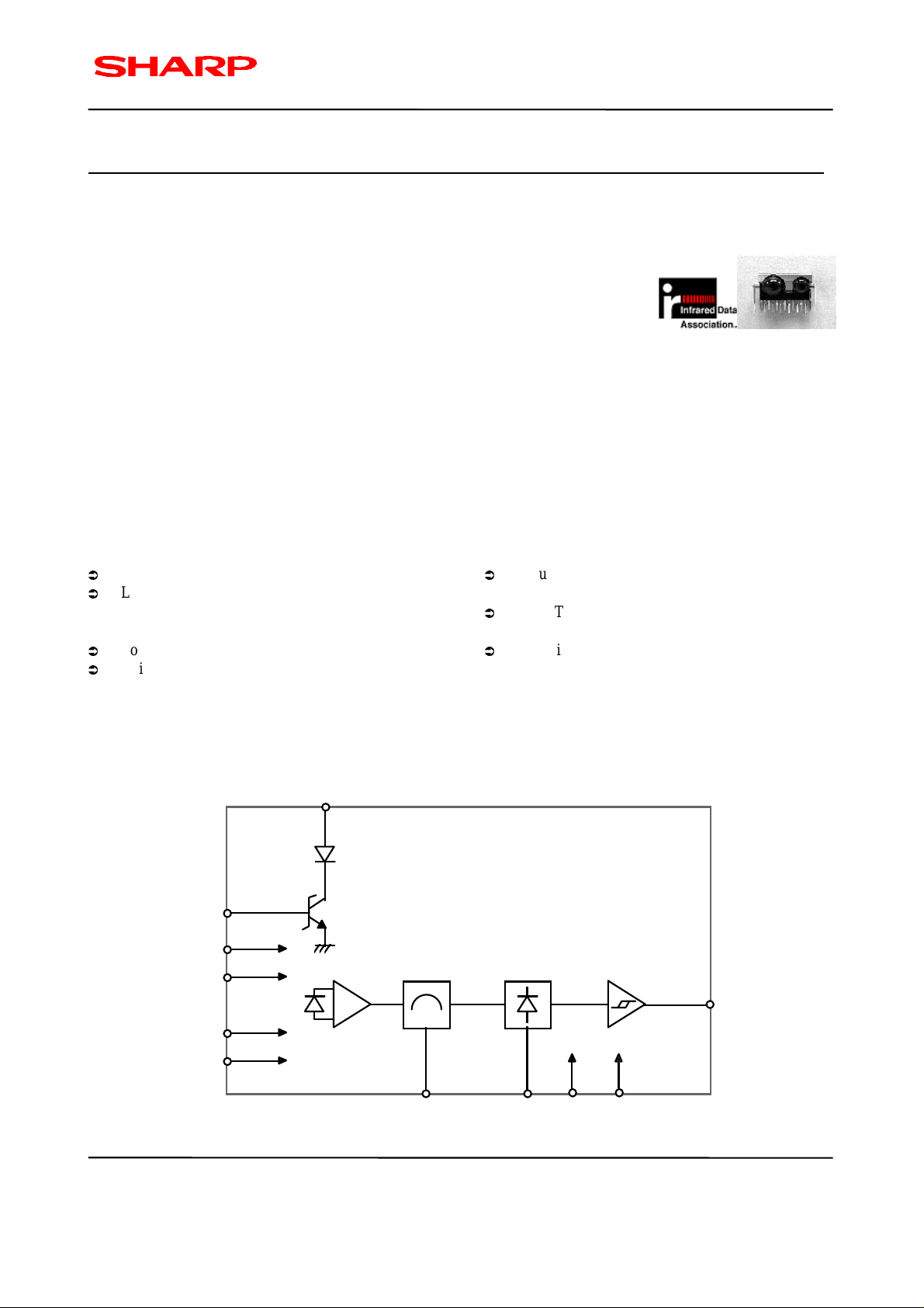
2. IrDA Control Infrared Transceiver Internal Block Diagram
LEDA
11
10
TXD
1
AVcc
DVcc
AGND
DGND
6
PIN
PD
5
7
AMP. B.P.F. Detect
943
f
O
CX RESET
SD
8
V
O
2
SHARP Electronic Components
Rev. 1.1.1
November 26, ‘98
Figure 2.1 GP2W2001YK Internal Block Diagram
4
Page 5

ELECTRONI C COMPON ENTS
(
)
3. Package Outline Dimensions ( TENTATIVE)
17.5
14.0
7.6
3.1
(3.7)
SHARP IrDA Control Infrared Transceiver
(6.3)
SHIELD CASE
4.5
(8.2)
0.45
1. Unspecified tolerance shall be ± 0.3(mm).
2. Resin burr shall not be included in outline dimensions.
3. Package Material : Visible Light Cut-off Resin (Color: Black)
4. Pin Assignment : See “Pinout” for details.
5. Lead pitch distance represents that of the lead root.
6. The appearance of the shieled case is TENTATIVE, and is subject to change without notice.
(0.89)
0.25
(2.1)
(0.84)
0.9
3.35
UNIT: mm
2.5
1.3
(1.25)
2.0
4. Absolute Maximum Ratings
Parameter Symbol Min. Max. Units Conditions
Supply Voltage V
Operating Temperature T
Storage Temperature T
Average Forward LED Current I
Peak Forward LED Current I
Transmitter Data Input Current I
Receiver Data Output Voltage V
Soldering Temperature T
CC
OP
ST
(DC) - 60 mA
LED
(PF) - 600 mA
LED
TXD
O
SOL
(NOTES)
1. The derating curve of peak forward current vs. ambient temperature is shown in section 11, figure 11.1.
2. The soldering should be done at the distance from 1.3mm from the resin edge of the transceiver module.
0 6.0 V
-10 70
-20 85
- 5.0 mA
-VCCV
- 260
o
C
o
C
*1
o
*2
C
, For 5s
SHARP Electronic Components
Rev. 1.1.1
November 26, ‘98
5
Page 6

ELECTRONI C COMPON ENTS
)
)
SHARP IrDA Control Infrared Transceiver
5. Recommended Operating Conditions
Parameter Symbol Min. Max. Units Conditions
Operating Temperature T
Supply Voltage V
Supply Voltage V
Transmitter Input Subcarrier
OP
CC1
CC2
fsc 1.484 1.517 MHz
-10 70
2.7 5.5 V Supply voltage for receiver side
4.25 5.25 V Supply voltage for emitter side
Frequency
Logic High Transmitter
V
IH (TXD
2.7 - V
Input Voltage (TXD)
Logic Low Transmitter
V
IL (TXD
0.0 0.3 V
Input Voltage (TXD)
0.4 1250
Logic High Receiver Input EI
IL
Irradiance 1.111 1250
LED (Logic High) Current
I
LEDA
400 - mA IE=100mW/sr,
Pulse Amplitude
Receiver Signal Rate D
RATE
74.175 75.825 kb/s
Receiver RESET Input Voltage Vrs_th 0.7 2.0 V
SD Recovery Time T
SD
-1msec
µ
W/cm
µ
W/cm
o
C
*3
Frequency accuracy within the
range of + 1.1%
2 *4
Θr < +30o, Φr < +15
*5
For in-band signals < 75.83kb/s
2 *4
Θr < +50o, Φr < +15
*5
For in-band signals < 75.83kb/s
*4 Θt < +15o, Φt < +15
Refer to
´
o
o
o
RESET Function
µ
[NOTES]:
3. IrDA Control system uses 16PSM coding scheme over 1.5MHz sub-carrier. See IrDA Control Physical Layer
Link Specification for the details of coding scheme and pulse characteristics.
4. See Figure 5.1 (below) for the viewing angle definition.
5. An in-band optical signal is a pulse/sequence where the peak wavelength λp, is defined as 850nm < λp <
900nm,
and the pulse characteristics are compliant with the IrDA Control Physical Layer Link Specification.
( ): TENTATIVE Value
Receiver
:
Θ
Horizontal (X-Axis)
Φ
: Vertical Angle (Y-Axis)
Θ
r, Φr
Θ
t, Φt
Θ
Transmitter
Φ
Figure 5.1 IrDA Control Transceiver Viewing Angle Criteria
SHARP Electronic Components
November 26, ‘98
Rev. 1.1.1
6
Page 7

ELECTRONI C COMPON ENTS
SHARP IrDA Control Infrared Transceiver
6. Electrical and Optical Specifications
Specifications hold over the Recommended Operating Conditions unless otherwise notified herein. Test Conditions
represent worse case values for the parameters under test. Unspecified test conditions can be anywhere in their
operating range. All typicals are at Ta=25
Parameter Symbol Min. Typ. Max. Units Conditions
RECEIVER SIDE
Current Dissipation I
S/D Current Dissipation Iccsd - 7.0 10.0
Receiver Data Logic High V
Output Voltage Logic Low V
Single Pulse tws 3.66 6.67 9.67
Pulse Width Double Pulse twd 10.33 13.33 16.34
Multi Pulse twm 50.36 53.36 56.36
Jitter tj -1.8 - +1.8
Receiver Data Output Rise Time tr - - 6.0
Receiver Data Output Fall Time tf - - 6.0
Receiver Detecting Distance L1 5.0 - - m
TRANSMITTER SIDE
Transmitter Radiant Intensity I
Peak Wavelength
Rise Time tr
Fall Time tf
(NOTES)
6. “L”: Low current consumption mode, “H” or OPEN: Normal operating mode.
7. The time difference or time gap from the pulse judgement criteria point of the output waveform at the 50% point
between V
and VOL.
OH
8: Receiver output wavelength definition:
o
C, and VCC=3.3V unless otherwise notified herein.
CC
- 5.0 7.0 mA No input IR signal, VCC=3.3V
µ
A
mode
VCC-0.5 - - V No input IR signal, High level
OH
OL
- - 0.5 V
µ
µ
µ
µ
µ
µ
sec *
sec *
sec *
sec
sec
sec
I
*
*
*
L2 3.0 - - m
E
100 - - mW/sr
I
λ
p
(IE)
(IE)
850 - 900 nm I
- - 80 nsec *
- - 80 nsec *
*6
at low current consumption
=400µA
OL
8,9
Input pulse width 6.33µs
8,9
Input pulse width 13.0µs
8,9
Input pulse width 53.00µs
7,8
8
8
*4
Θr = 30o, Φr = 15
*4
Θr = 50o, Φr = 15
*4
Θt < +15o, Φt < +15
=400mA
LED
=400mA
LED
9,10
9,10
o
o
o
VOH
90%
50%
10%
Criterion for
Pulse Position
SHARP Electronic Components
Rev. 1.1.1
November 26, ‘98
tj tws, twd, twm
tf tr
VOL
Figure 6.1 GP2W2001YK Receiver Output Waveform
90%
50%
10%
7
Page 8

ELECTRONI C COMPON ENTS
9: Emitter output wavelength definition:
Pulse Width
SHARP IrDA Control Infrared Transceiver
90%
50%
10%
tr tf
IE
Figure 6.2 GP2W2001YK Emitter Output Waveform
10: Recommended Circuit for Emitter Side:
4.7Ω
LEDA
TX
GP2W2001YK
Ω
The output signal shown above (Figure 6.2) should be obtained by
applying the “recommended circuit for emitter side” shown right.
V
=3.0V
IH
V
=5V
cc2
560pF
820
7. Pinout
Pin Description Sy mbol
1 Analog Supply Voltage AV
2 Shut Down for Low Current Consumption SD
3 RESET Terminal for Receiver Sensitivity Recovery RESET
4 - CX
5 Analog Ground AGND
6 Digital Supply Voltage DV
7 Digital Ground DGND
8 Receiver Data Output V
9 Bandpass Filter f
10 Transmitter Data Input TXD
11 IRLED Anode LEDA
0
6.67µs
100mW/sr
T
CC
CC
O
PIN 1 PIN 11
PIN 11 PIN 1
SHARP Electronic Components
Rev. 1.1.1
November 26, ‘98
8
Page 9

ELECTRONI C COMPON ENTS
SHARP IrDA Control Infrared Transceiver
8. Application Circuit and Recommended Components
Parts Recommended Value
CX1 470pF, + 10%, Ceramic
CX2
0.1µF, + 10%, Ceramic
CX3
4.7µF, + 20%, Aluminum
CX4
0.1µF, + 10%, Ceramic
CX5 560pF, + 10%, Ceramic
R1
10Ω, + 5%, 0.125 Watt
R2
8.2kΩ, + 1%, 0.125 Watt
R3
820 Ω, + 5%, 0.125 Watt
R4
4.7Ω, + 5%, 0.5 Watt
Receiver
1
2 3
CX1
5
4
6
CX4
7 8
R2
Transmitter
9 10 11
FERESET
RxCNT
R1
3.3V
CX2
CX3
IRRX
R3
IRTX
CX5
R4
Ç
LED
I
=400mA
5V
Figure 8.1 GP2W2001YK Application Circuit Example
9. Waveform Examples
The following diagram shows and example of IrDA Control implementation using Sharp IrDA Control Infrared
Transceiver. The waveform of the implemented system with Sharp IrDA Control Infrared Transceiver will be as shown
below:
cc2
LEDA
TXD
V
I
II
Vo
IRTx1
IRRx1
Section Waveform
I
16PSM code x 1.5MHz
RESET
SD
Figure 9.1 IrDA Control Transceiver Implementation
SHARP Electronic Components
Rev. 1.1.1
November 26, ‘98
FRESET
RxCNT
II
Receiver Original Output
9
Page 10

ELECTRONI C COMPON ENTS
SHARP IrDA Control Infrared Transceiver
10. RESET Function
The “RESET” terminal is used to recover the receiver sensitivity to its maximum level. Since Sharp IrDA Control
Infra red Tra nsc eiver h as a built-in cap abilit y to adj us t t he r eceiving sensitivity, as a result, a very weak IR signals may
not be correctly received just after receiving a very strong IR signals.
Following figure shows an example of “RESET” signal in order to recover the Sharp IrDA Control Infrared
Transceiver’s receiving sensitivity to its receiving sensitivity to its maximum level:
Optical
Signal
Gap Time
Vo
RESET
input
> 13µsec
AGCN
tret: The time period until AGCN
tret
(NOTES)
This pinout is an Active Low terminal, and stays HIGH level when it is OPEN. The Low Level Pulse for the period of
> 13µsec enables this function to work. This >
13µsec input must be pulsed within the period of Gap time in order for
the transceiver to have receiver sensitivity recovery. The timing for this “RESET” pulse should be adjusted at
controller side.
11. The Derating Curve of Peak Forward LED Current
600
500
(mA)
FM
400
300
200
Peak Forward Current : I
100
0
-25 0 25 50 75 100
-10 70
Ambient Temperature : Ta (
o
C)
Figure 11.1 Derating Curve of Peak LED Current
SHARP Electronic Components
Rev. 1.1.1
November 26, ‘98
(Pulse width < 3.3µsec, Duty Ratio <
25%)
10
Page 11

ELECTRONI C COMPON ENTS
SHARP IrDA Control Infrared Transceiver
LIFE SUPPORT POLICY
SHARP components should not be used in medical devices with life support functions or in safety equipment (or
similar applications where component failure result in loss of life or physical harm) without the writte n approval of an
officer of the SHARP Corporation.
SHARP reserves the right to make changes in specifications at any time and without notice. SHARP does not assume
any responsibility for the use of any circuitry described; no circuit patent licenses are implied.
SHARP Electronic Components
Rev. 1.1.1
November 26, ‘98
11
Page 12

ELECTRONI C COMPON ENTS
SHARP CORPORATION Japan
INTERNATIONAL SALES & MARKETING GROUP
-IC/ELECTRONIC COMPONENTS
22-22 Nagaike-cho, Abeno-ku, OSAKA, 545, JAPAN
PHONE: (81) 6-621-1221
FAX: (81) 6-624-0163
NORTH AMERICA:
SHARP ELECTRONICS CORPORATION
Microelectronics Group
5700 Northwest, Pacific Rim Boulevard#20
Camas, WA, 98607, U.S.A.
PHONE: (1) 360-834-2500
FAX: (1) 360-834-8903
EUROPE:
SHARP ELECTRONICS (EUROPE) GmbH
Microelectronics Division
Sonninstrasse 3, 20097 Hamburg, Germany
PHONE: (49) 40-2376-2286
FAX: (49) 40-2376-2232
SHARP IrDA Control Infrared Transceiver
TAIWAN:
SHARP ELECTRONIC COMPONENTS (TAIWAN)
CORPORATION
8 Fl., No. 16, Sec 4, Nanking E Rd.,
Taipei, T aiwan, Republic of China
PHONE: (886) 2-577-7341
FAX: (886) 2-577-7326 / 2-577-7328
HONG KONG
SHARP - ROXY (HONG KONG) LTD.
3rd Business Division,
Room 1701 - 1711, Admiralty Centre Tower 1,
Harcourt Road, Hong Kong
PHONE: (852) 28229311
FAX: (852) 28660779
SINGAPORE:
SHARP ELECTRONICS (SINGAPORE) PTE., LTD.
438A, Alexandra Road, #05-01/02,
Alexandra Technopark, Singapore 119967
PHONE: (65) 271-3566
FAX: (65) 271-3855
KOREA:
SHARP ELECTRONIC COMPONENTS (KOREA)
CORPORATION
RM 501 Geosung B/D.
541, Dohwa-dong, Mapo-ku, Seoul, Korea
PHONE: (82) 2-711-5813 ~ 8
FAX: (82) 2-711-5819
SHARP Electronic Components
Rev. 1.1.1
November 26, ‘98
12
 Loading...