

Page 1
GP2S30
GP2S30
Long Focal Distance Type
Photointerrupter with
Connector
■ Features
1. Long focal distance
Detection distance: 3 to 7mm
2. High sensing accuracy by laser
trimming of resistor
3. 3-pin connector
■ Applications
1. Printers
2. Facsimiles
3. Copiers
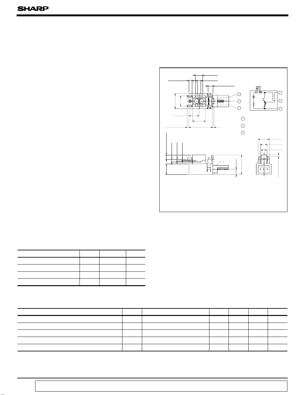
■ Outline Dimensions
±
0.3
2 - 2.0
0.4-0.2
+
7.0
10.0
±
0.3
7.0
±
0.3
2 - 1.0
0.3
±
2 - 2.7
2 - 1.6
2 - 1.2
2 - 1.0
+ 0.4
- 0.2
7.0
❈❈ Recommended connectors on the inserted side
are shown on the below page.
2 - 4.5
2 - 2.5
9.0
±
0.3
16.0
GP2S30
∗Tolerance:± 0.2mm
∗( ): Reference dimensions
❈ Japan AMP made EI 3pin connector 171825-3
Recommended connector on the
inserted side 172053-3, etc. ❈❈
2- 3.0
0.8
❈
±
0.3
1
2
3
1
Vo
Vcc
2
3
GND
)
0.5
±
3.15
(
13.0
(
Unit : mm
Internal connection
diagram
±
7.6
5.0
±
4.0
)
1
2
3
0.3
0.3
0.5
±
1.0
-
2
■ Absolute Maximum Ratings
(
Ta= 25˚C
)
Parameter Symbol Rating Unit
Supply voltage V
Output current I
∗1
Operating temperature T
∗1
Storage temperature T
CC
opr
stg
O
- 0.5 to + 7
1mA
- 20 to + 70
- 40 to + 80
∗1 The connector should be plugged in/out and the unit's hook should be used at normal temperature.
■ Electro-optical Characteristics
V
˚C
˚C
(
VCC= 5V, Ta= 25˚C unless otherwise specified
Parameter Symbol Conditions MIN. TYP. MAX. Unit
Operating supply voltage V
Dissipation current I
Low level output voltage V
High level output voltage V
Ta=- 20 to + 70˚C 4.5 5.0 5.5 V
CC
∗2
At detecting, d= 5mm - 26 35 mA
CC
∗3
At non-detecting, d= 5mm - 0.2 0.8 V
OL
∗2
At detecting, d= 5mm 2.1 3.0 3.9 V
OH
Response frequency f ∗4 - - 170 Hz
∗2 At detecting : White PPC paper as a reflective object without external disturbing light in Fig. 1.
∗3 At non-detecting : Black suede tape as a reflective object without external disturbing light in Fig. 1.
∗4 The definition of response frequency is shown in Fig. 2.
“ In the absence of confirmation by device specification sheets, SHARP takes no responsibility for any defects that occur in equipment using any of SHARP's devices, shown in catalogs,
data books, etc. Contact SHARP in order to obtain the latest version of the device specification sheets before using any SHARP's device.”
)
Page 2
GP2S30
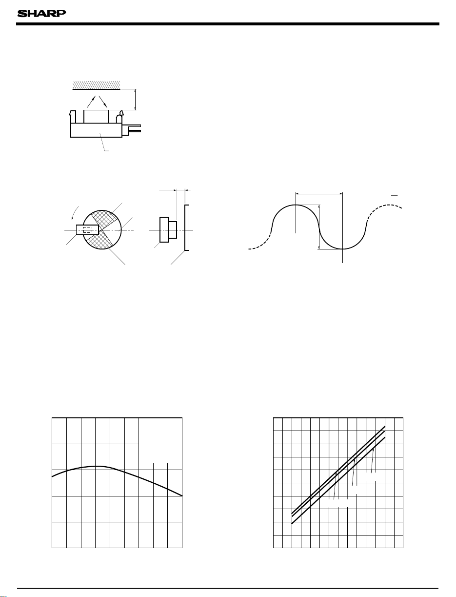
Fig. 1 Test Condition for V
Reflective
object
O
d= 5mm
GP2S30
Fig. 2 Definition of Response Frequency
5mm
Rotation
GP2S30
Black
White
GP2S30
Rotating disk
φ>= 40mm
VO waveform
T
V
OH
V
H-L
V
OL
Response frequency:Rotational frequency f when V
decreases 3dB from DC.
1
f=
T
H-L
Fig. 3 Relative Output Voltage vs.
Ambient Temperature
120
110
)
%
(
100
90
Relative output voltage
80
70
- 20 0 20 40 60 70
Ambient temperature Ta (˚C
VCC=5V
d= 5mm
Reflective object:
PPC paper(white
Fig. 4 Dissipation Current vs.
Supply Voltage
30
)
)
)
mA
(
CC
25
Dissipation current I
20
4.5 5.0 5.5
25˚C
= 70˚C
T
a
Supply voltage VCC (V
- 20˚C
)
Page 3

GP2S30
Fig. 5 Relative Output Voltage vs.
Detecting Distance
100
80
)
%
(
60
40
Relative output voltage
20
0
0481216
Distance between GP2S30 and reflector d (mm
VCC=5V
Reflective object:PPC paper(White
Fig. 7 Relative Collector Voltage vs.
Reflector Moving Distance (2
VCE= 5V, d= 5mm
Reflective object:PPC paper(White
100
)
%
(
80
60
40
Relative collector current
20
Art work tape(black
L
-
0
Fig. 6 Relative Collector Voltage vs.
Reflector Moving Distance (1
= 5V, d= 5mm
V
CC
)
d
20
)
100
)
%
(
80
60
40
Relative collector current
20
0
-5 0
Reflective object:PPC paper(White
Art work tape(black
Reflector moving distance L(mm)
)
)
)
L
-
+
d
0
5
)
)
)
+
d
0
Reflector moving distance L(mm
0-5
Recommended Mounting Holes (mm
Board thickness 1.6
7.4
5.3
2
GP2S30
-
2
Mounting Method
5
)
)
+ 0.17
mm
- 0.12
7
16
Board thickness 1.2
4
-
2
Recommended Mounting Holes
7.3
5.3
+ 0.17
mm Board thickness 1.0
- 0.12
7
16
+ 0.17
mm
- 0.12
7.2
5.3
7
-
2
7
16
Page 4

■ Recommended Connectors on the Inserted Side
● JAPAN AMP made El series connector
(
standard type
Housing color
Housing Model No.
Special
terminal
Model No.
■ Recommended Circuit
)
Natural
171822-3 2-171822-3 4-171822-3 6-171822-3 8-171822-3
26 to 20
30 to 26
Black Blue Green Red
color
AWG
size
AWG
Product
shape
Chain
Bulk
AWG
Chain
Bulk
Object
R
1
R
2
Material Model No.
Brass 170204-1
phosphor
bronze
Brass
phosphor
bronze
Brass 170205-1
phosphor
bronze
Brass 170263-1
phosphor
bronze
GP2S30
170204-2
170262-1
170262-2
170205-2
170263-2
V
CC
V
OUT
GND
R
R
●JAPAN AMP made Series connectors
●JAPAN AMP made Series connectorsEI
∗ Terminal Material: phosphor bronze
3
+
Comp.
-
4
(low profile type
Housing color
Housing Model No.
Special
terminal
Model No.
(
Material:
phosphor
)
bronze
(
amp. mass termination
Housing
terminal
united type
connector
R
5
)
Natural
172142-3 2-172142-3 4-172142-3 6-172142-3 8-172142-3
26 to 22
30 to 26
R
6
Black Blue Green Red
color
AWG
Product shape
size
AWG
AWG
AWG28
(
Green
172054-3 172053-3 172052-3 172051-3
V
CC
V
OUT
GND
GP2S30
EI
Model No.
Bulk 170369-1
Chain 170354-1
Bulk 170370-1
Chain 170355-1
)
AWG26
(
)
Natural color
AWG24
)
(
Black
)
AWG22
(
Red
)
■ Precautions for Use
(1)
In this product, the PWB is fixed with a hook, and cleaning solvent may remain inside the
case; therefore, dip cleaning or ultrasonic are prohibited.
(2)
Remove dust or stains, using an air blower or a soft cloth moistened in cleaning solvent.
However, do not perform the above cleaning using a soft cloth with cleaning solvent in the
marking portion.
In this case, use only the following type of cleaning solvent used for wiping off:
Ethyl alcohol, Methyl alcohol, Isopropyl alcohol,
When the cleaning solvents except for specified materials are used, please consult us.
(3)
As for other general cautions, refer to the chapter “Precautions for Use .”
 Loading...