

Page 1
GP1A21
GP1A21
OPIC Photointerrupter with
Connector
■ Features
1. Snap-in mounting type
2. Uses 3-pin connector terminal
3. High sensing accuracy (Slit width : 0.5mm
4. Wide gap between light emitter and detec tor (5mm
)
■ Applications
1. Copiers
2. Printers
3. Facsimiles
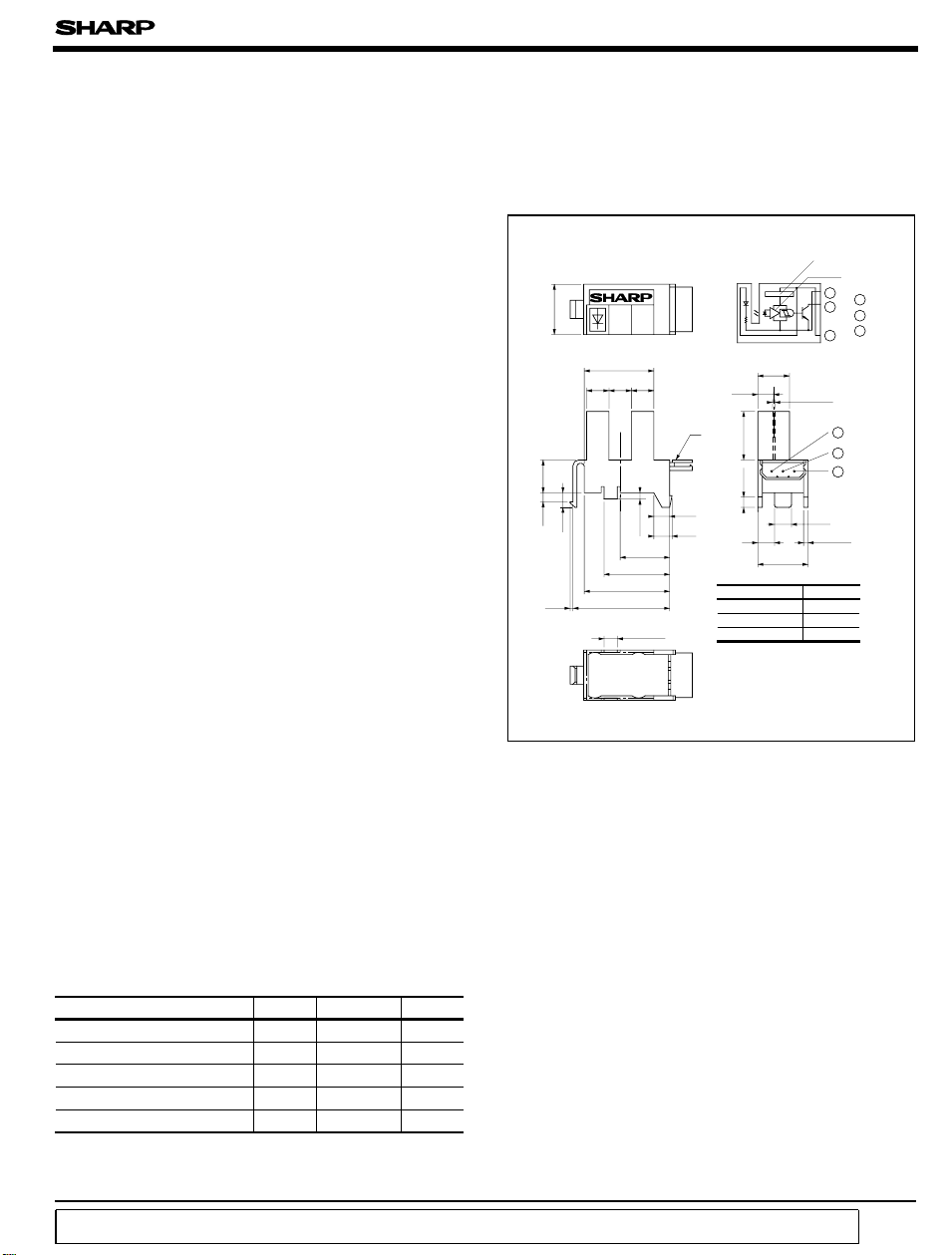
■ Outline Dimensions
Internal connection diagram
)
10.8
15.5
5.0 5.0 5.0
7.0
1.1
1.6
0.9
*“ OPIC” (Optical IC) is a trademark of the SHARP Corporation.
An OPIC consists of a light-detecting element and signal processing circuit integrated onto a single chip.
Note) Terminal No. shown in the above figure is
sometimes different from the number shown
on the connector.
11.8
15.8
19.8
22.0
3.0
1.5
±
0.1
±
0.1
3.4
❈
11.0
2 - 1.6
3.0
4.0
3.4
* Unspecified tolerances shall be as follows;
Dimensions(d)Tolerance
5.0<=d< 15.0 ± 0.2
15.0<=d ±0.3
* ( ): Reference dimensions
❈ MOLEX JAPAN CO., LTD.
made connector 5267-03A
Recommended connectors on
the inserted side
Housing : 5264-03
Terminal: 5263 PBT etc.
(
Unit : mm
Voltage regulator
Amp.
1
2
3
6.8
Slit width
±
0.1
0.5
4.0
2 - 0.9
±0.1
10.8
d< 5.0 ± 0.15
3
2
1
1 GND
2 V
O
3 V
CC
)
■ Absolute Maximum Ratings
(
Ta= 25˚C
)
Parameter Symbol Rating Unit
I
CC
O
OL
opr
stg
- 0.5 to + 7
- 0.5 to + 28
50 mA
- 20 to + 75
- 30 to + 85
Supply voltage V
*1
Output voltage V
*2
Low level output current
*3
Operating temperature T
*3
Storage temperature T
*1 Collector-emitter voltage of output transistor
*2 Collector current of output transistor
“ In the absence of confirmation by device specification sheets, SHARP takes no responsibility for any defects that occur in equipment using any of SHARP's devices, shown in catalogs,
data books, etc. Contact SHARP in order to obtain the latest version of the device specification sheets before using any SHARP's device.”
V
V
˚C
˚C
*3 The connector should be plugged in/out and the unit's hook
should be used at normal temperature.
Page 2
GP1A21
■ Electro-optical Characteristics
(
Unless otherwise specified, V
Parameter Symbol Conditions MIN. TYP. MAX. Unit
Operating supply voltage V
Low level supply current I
Low level output voltage V
High level supply current I
High level output voltage V
*5
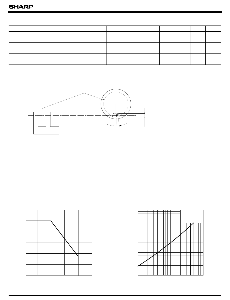
Response frequency
*4 Output should not be DC level.
*5 Response frequency is measured with the disk shown below being rotated. (Unit: mm
Disk
CC
Light beam uninterrupted - - 30 mA
CCL
Light beam uninterrupted, IOL= 16mA
OL
Light beam interrupted - - 30 mA
CCH
Light beam interrupted, R
OH
*4
RL= 47kΩ−−Hz
f
0.5
0.5
)
= 47kΩ
L
2.0
= 5V, Ta= 25˚C
CC
4.5 - 5.5 V
- - 0.35 V
VCCx0.9
--V
3 000
)
Fig. 1 Low Level Output Current vs.
Ambient Temperature
60
)
50
mA
(
OL
40
30
20
Low level output current I
10
0
-20
0
Ambient temperature Ta (˚C
)
Fig. 2 Low Level Output Voltage vs.
Low Level Output Current
1.0
0.5
)
V
(
OL
0.2
0.1
0.05
Low levle output voltage V
0.02
100755025
0.01
Low level output current I
VCC=5V
T
= 25˚C
a
(mA
OL
502052
100101
)
Page 3

GP1A21
Fig. 3 Low Level Output Voltage vs.
Ambient Temperature
0.6
VCC=5V
)
0.5
V
(
OL
0.4
0.3
0.2
Low levle output voltage V
0.1
0
-25
0
IOL= 30mA
25 50 75 100
Ambient temperature Ta (˚C
16mA
5mA
)
Fig. 5 Detecting Position Characteristics (1
=5V
V
CC
T
= 25˚C
a
R
=
L
47kΩ
d
Shield
Output OFF
Fig. 4 Supply Current vs.Supply Voltage
30
)
mA
(
20
CC
I
{
CCL
I
CCH
10
Supply current I
0
4.5 5.0 5.5
Supply voltage VCC (V
)
Fig. 6 Detecting Position Characteristics (2
=5V
V
CC
T
= 25˚C
a
R
= 47kΩ
L
Shield
Ta=- 20˚C
=- 20˚C, + 25˚C, + 75˚C
T
a
)
h
+ 25˚C
+ 75˚C
)
Output OFF
Output ON
0
Detecting position d=3.4
Shield distance d (mm
754321
6 7654321
)
± 0.3
mm Detecting posititon h= 4.2
0
Shield distance h (mm
± 1.5
■ Recommended Mounting Holes (Following dimensions are recommended values, so confirm the
+ 0.2
)
- 0
21.9
)
intencity by using actual equipment before mounting.
4.5
10.2
+ 0.2
-
+
-
0
0
0.2
-
+
3.2
0.1
0
0.2
±
-
+
4.0
16.0
0.2
0
+ 0.17
1.0
-
0.12
Mounting method
±
0.1
2.85
Recommended mounting holes (Unit : mm
ON
Output
)
mm
Page 4

■ Precautions for Use
(1) In this product, the PWB is fixed with a resin cover, and cleaning solvent may remain
inside the case; therefore,dip cleaning or ultrasonic cleaning are prohibited.
(2) Remove dust or stains, using anair blower or soft cloth moistened in cleaning solvent.
However, do not perform the above cleaning using a soft cloth with cleaning solvevt in the
marking portion.
In this case use only the following type of cleaning solvent used for wiping off:
Ethyl alcohol, Methyl alcohol, Isopropyl alcohol.
When the cleaning solvents except for specified materials are used, please consult us.
(3) In order to stabilize power supply line, connect a by-pass capacitor of more than 0.01µF
between Vcc and GND near the device.
(4) As for other general cautions, refer to the chapter “Precautions for Use .”
GP1A21
 Loading...