

Page 1
GP2010
GPS Receiver RF Front End
Supersedes edition in August 1996 Global Positioning Products Handbook, HB4305-1.0 DS4056 - 3.4 October 1996
The GP2010 is Mitel Semiconductor second generation
RF Front-end for Global Positioning System (GPS) receivers.
The GP2010 uses many innovative design techniques and a
leading-edge bipolar process to offer a low power, low cost
and high reliability RF Front End solution . The GP2010 is
designed to operate from either 3 or 5 Volt power supplies.
The input to the device is the L1 (1575.42MHz) CoarseAcquisition (C/A) code Global Positioning signal from an
antenna (via a low-noise pre-amplifier). The output is 2-bit
quantised for subsequent signal processing in the digital
domain. The GP2010 contains an on-chip synthesiser, mixers,
AGC and a quantiser which provides Sign and Magnitude
digital outputs. A minimum of external components is required
to make a complete GPS front-end.
The device has been designed to operate with the GP2021
12-channel Global Positioning Correlator, and DW9255 SAW
filter, both also available from Mitel Semiconductor.
FEATURES
■ Low Voltage Operation (3V - 5V)
■ Low Power - 200mW typ. (3V supply)
■ C/A Code Compatible
■ On-chip PLL Including Complete VCO
■ Triple Conversion Receiver
■
44-Lead Surface Mount Quad Flat-Pack Package
■ Sign and Magnitude Digital Outputs
■ Compatible with GP2021 CMOS Correlator
APPLICATIONS
■ C/A Code Global Positioning by Satellite Receivers
■ Time Standards
■ Navigation
■ Surveying
Pin
1
2
3
4
5
6
7
8
9
10
11
12
13
14
15
16
17
18
19
20
21
22
24
25
26
27
28
29
30
31
32
33
34
35
36
37
38
39
40
41
42
43
44
IF Output
PLL Filter 1
PLL Filter 2
(OSC)
V
EE
(OSC)
V
CC
(OSC)
V
EE
VEE (REG)
PRef
PReset
(IO)
V
EE
CLK
MAG
SIGN
IK-
OPC
OPCIK+
VDD (IO)
N
PD
TEST
LD
(DIG)
V
EE
AGC AGC +
1
Name
GP
43 2
2010
Pin
23
24
25
26
27
28
29
30
31
32
33
34
35
36
37
38
39
40
41
42
43
44
10
98765
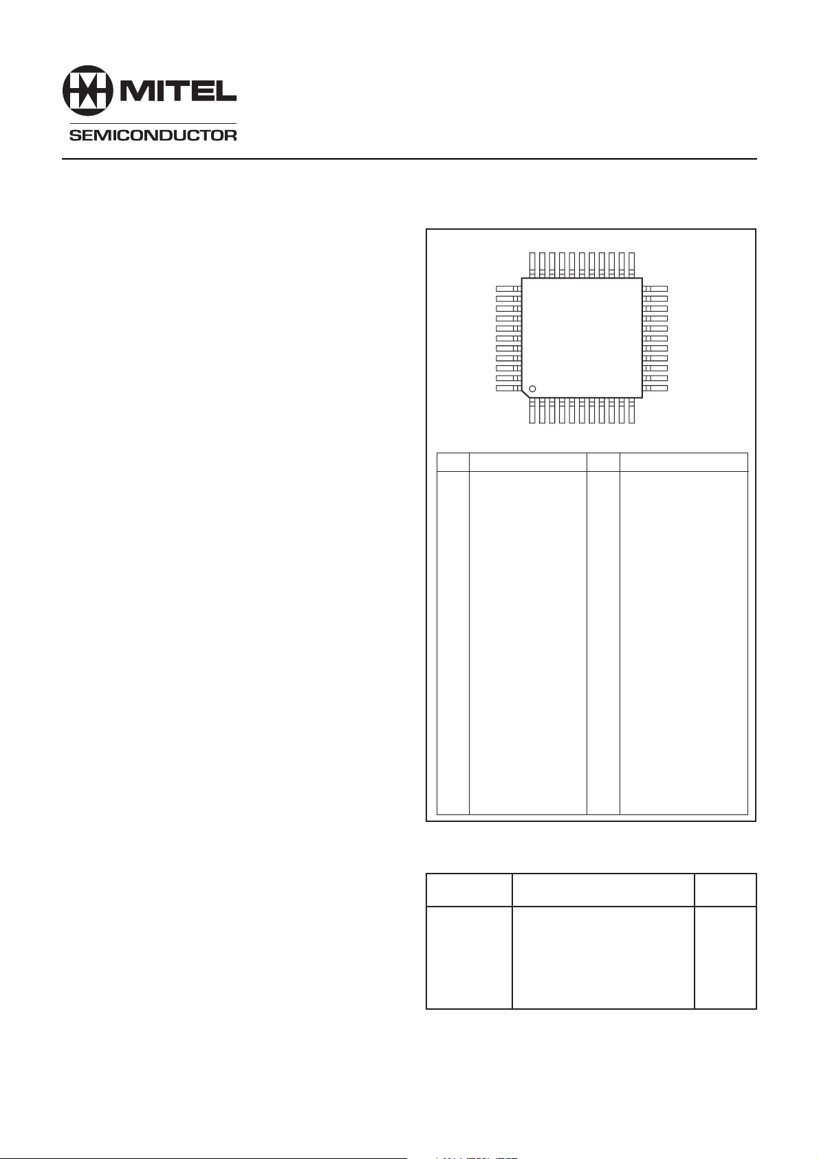
Fig. 1 Pin connections - top view
23
11
(DIG)
V
CC
REF 2
REF 1
(RF)
V
CC
(RF)
V
EE
(RF)
V
EE
RF Input
(RF)
V
EE
(RF)
V
EE
(RF)
V
CC
O/P 1O/P 1+
(2)
V
CC
I/P 2I/P 2+
(IF)
V
EE
(IF)
V
EE
O/P 2O/P 2+
(3)
V
CC
I/P 3I/P 3+
22
21
20
19
18
17
16
15
14
13
12
Name
GP
44
ORDERING INFORMATION
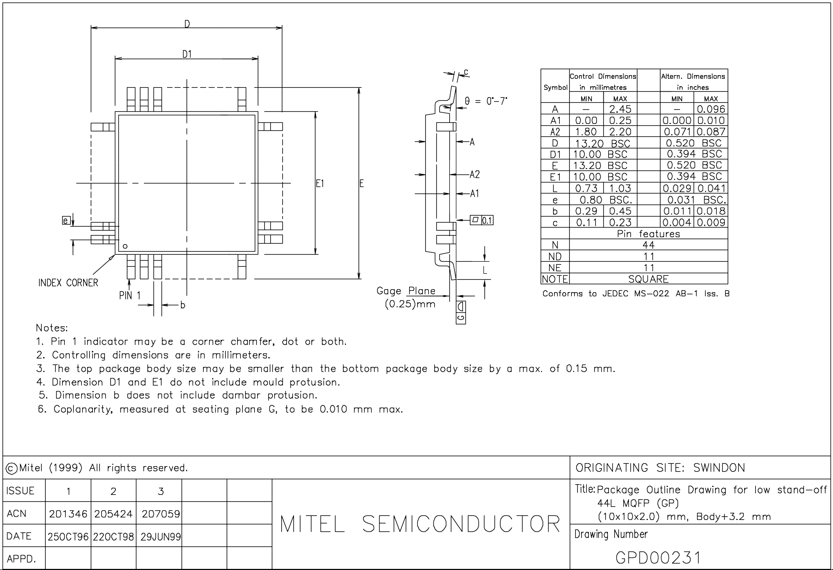
The GP2010 is available in 44 pin Quad Flat pack (gullwing
formed leads) to Industrial (-40°C to +85°C) grade.
ORDERING CODE
GP2010 IG GPBR Industrial - Plastic 44-pin PQFP
RELATED PRODUCTS AND PUBLICATIONS
Part
DW9255
GP2021
GPSBuilder-2
GP2010
GP2015
GP2015
35.42MHz SAW Filter
Twelve-Channel Correlator
Twelve-Channel GPS receiver
development system
Design with the GP2010
Small RF Format Front End
Design with the GP2015
Description
Reference
Data
DS3861
DS4057
DS4004
AN4364
DS4374
AN4533
Page 2
GP2010
ABSOLUTE MAXIMUM RATINGS
(Non-simultaneous)
Max. Supply Voltage 7V
Max. RF Input +15dBm
Max. voltage on any pin V
except LD (pin 19) and PReset (pin 9), which are 5.5V
CC/VDD
+ 0.5V
Min. voltage on any pin VEE - 0.5V
Storage Temperature -65°C to +150°C
Operation Junction Temperature -40°C to +150°C
10MHz Reference Input 1.5V pk -pk
ESD PROTECTION
The GP2010 device is static sensitive. The most
sensitive pins withstand a 750V test by the human body
model. Therefore, ESD handling precautions are essential to
avoid degradation of performance or permanent damage to
this device.
PRODUCT DESCRIPTION
The GP2010 receives the 1575.42MHz signal
transmitted by GPS satellites and converts it to a 4.309MHz
IF, using a triple down-conversion. The 4.309MHz IF is
sampled to produce a 2-bit digital output. If the GP2010 is
used in conjunction with the GP2021 correlator, then the
GP2021 provides a sampling clock of 5.714MHz. This converts
the IF to a 1.405MHz 2-bit digital output at TTL levels.
The GP2010 can operate from a single supply from
+3V (nominal) to +5V (nominal).
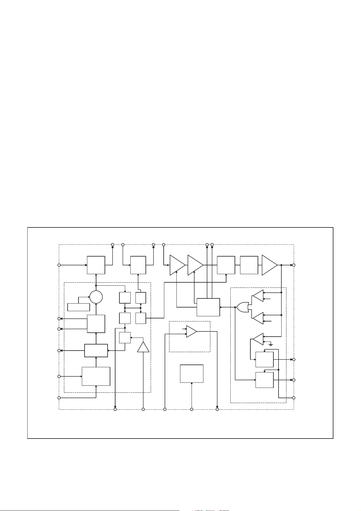
A block diagram of the circuit is shown in figure 2.
IF STRIP
The input signal to the GP2010 is the GPS L1 signal
received via an antenna and a suitable LNA. The L1 input is
a spread spectrum signal at 1575.42MHz with 1.023Mbps
BPSK modulation. The signal level at the antenna is about
-130dBm, spread over a 2.046MHz bandwidth, so the wanted
signal is actually buried in noise. The high RF input compression
point of the GP2010 means that with subsequent IF filtering
it is possible to reject large out of band jamming signals, in
particular 900MHz as used by mobile telephones.The on-chip
PLL generates the first local-oscillator frequency at 1400MHz.
The output of the front-end mixer (Stage 1) at 175.42 MHz can
then be filtered before being applied to the second stage. The
double-balanced stage 1 mixer outputs are open-collectors,
and require external dc bias to V
CC
.
The second stage contains further gain and a mixer
with a local oscillator signal at 140 MHz giving a second IF at
35.42 MHz. The second stage mixer is also double-balanced
with open-collector outputs requiring external dc bias to V
CC
The signal from stage 2 is passed through an external
filter with a 1dB bandwidth of 1.9MHz. The performance of this
filter is critical to system performance and it is recommended
that a SAW filter is used (part number DW9255, also available
from Mitel Semiconductor). The output of the filter then feeds
the main IF amplifier. This includes 2 AGC amplifiers and a
third mixer with a local oscillator signal at 31.111 MHz giving
a final IF at 4.309 MHz. There is an on-chip filter after the third
mixer which provides filtering centred on 4.309 MHz. The IF
output, which has 1kΩ output impedance, is provided for test
purposes. All of the signals within the IF amplifier are differential
including the filter inputs and outputs, except the IF output (pin
1), to reduce any common mode interference.
.
RF Input
EXTERNAL
LOOP
FILTER
PLL LOCK
LOGIC O/P
(LD)
PLL REF I/P
10MHz (REF 2)
REF 1 I/P
(FOR USE WITH
CRYSTAL REF
ONLY)
(29)
(2)
(3)
(19)
(24)
(25)
L1
(1575.42MHz)
VOLTAGE
REGULATOR
175.42MHz FILTER
(33,34) (36,37) (40,41) (43,44) (21) (22)
FRONT
END
MIXER
1.400GHz
VCO
PLL
LOOP
FILTER
PHASE
DETECTOR
PLL
REFERENCE
OSCILLATOR
40MHz CLOCK O/P
(FOR CORRELATOR
(14, 15)
CHIP)
(OPCIK +/-)
÷5 ÷5÷5
÷7÷4÷9
1.400GHz
PHASE-
LOCKED
LOOP
35.42MHz FILTER
2nd
STAGE
MIXER
÷2
BITE
(TEST)
POWER-ON
REFERENCE
I/P
(PREF)
AGC AGC
+1.21V
POWER-ON
_
+
RESET
POWER
CONTROL
POWER
DOWN I/P
(PDn)
AGC CAPACITOR
AGC
CONTROL
POWER-ON
RESET O/P
(PRESET)
3rd
STAGE
MIXER
(9)(17)(8)(18)
31.11MHz140MHz
4.3MHz
FILTER
SIGN
O/P
LATCH
MAG
O/P
LATCH
A -> D
CONVERTER
(1)
IF Output
(4.309MHz)
+Vr
-Vr
(13)
SIGN
TTL O/P
(12)
MAG
TTL O/P
(11)
SAMPLE
CLOCK I/P (CLK)
(5.71MHz TTL)
Fig. 2 Block diagram of GP2010
2
Page 3

The IF output is fed to a 2-bit quantiser which provides
sign and magnitude (MSB and LSB) outputs. The magnitude
data controls the AGC loop, such that on average the magnitude
bit is set (high) 30% of the time. The AGC time constant is set
by an external capacitor.
The sign and magnitude data, SIGN (pin 13) and MAG (pin
12), are latched by the rising edge of the sample clock, CLK
(pin 11), which is normally derived from the correlator; the
GP2021 provides a 5.714MHz (=40/7) clock, giving a sampled
IF centred on 1.405MHz.
The Digital Interface circuits use a separate power-supply,
V
(IO), which would normally be shared with the correlator to
DD
minimise crosstalk between the analog and digital sections of
the device.
ON-CHIP PHASE-LOCKED LOOP SYNTHESISER
All of the local oscillator signals are derived from an on
chip phase locked loop synthesiser. This includes a 1400MHz
VCO complete with on-chip tank circuit, dividers and phase
detector, with external loop filter components. A 10.000MHz
reference frequency is required for the PLL. This can be
achieved by attaching an external 10.000MHz crystal to the
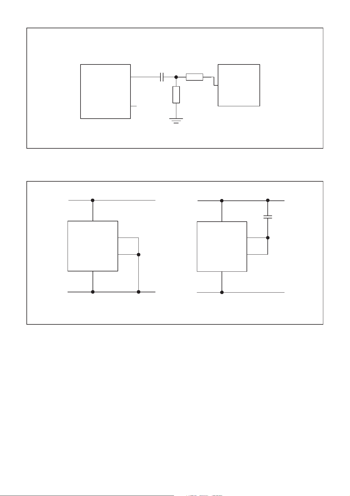
on-chip PLL reference oscillator (see figure 5). However in
most applications the user will need an external source, such
as a TCXO, to provide greater frequency stability (see figure
6). An external reference should be ac coupled to REF2 (pin
24); REF 1 (pin 25) should be left open circuit.
The three local oscillator signals 1400MHz, 140.0MHz
and 31.11MHz are derived from the 1400MHz synthesiser
output. The synthesiser also provides a 40 MHz balanced
differential output clock (pins 14 & 15) which can be used to
clock the GP2021 correlator. The clock is a low level differential
signal which helps minimise interference with the analog
areas of the circuit. A PLL lock-detect output, LD (pin 19), is
also provided, which is logic high when the PLL is phaselocked to the 10.000MHz reference signal.
The VCO power-supply incorporates an on-chip
regulator to improve the noise-immunity of the PLL. This
feature is only available when operating with a 5 volt (nominal)
supply which is regulated to 3.3 volts internally. This internal
regulated supply is referenced to V
(OSC) (pin 5). Figure 7
CC
shows the required connections for both 3 volt and 5 volt
operation.
A further feature of the circuit is the TEST input (pin 18).
When this input is held high the PLL is unlocked with the VCO
at its maximum frequency.
GP2010
POWER-DOWN CAPABILITY
A power down function is provided on the GP2010, to
limit power consumption. This powers down the majority of
the circuit except the “power-on reset” function (see below).
If the power down feature is not required, the Powerdown input, PD
(=Vee/Ground).
POWER-ON RESET FUNCTION
The GP2010 includes a voltage detector which
operates from the digital interface supply. This circuit is used
to produce a TTL logic low output while the GPS receiver
power supply is switching on, and produces a logic high
output when the power supply voltage has achieved a nominal
value. This output can be used to disable the GP2021
correlator while the power supply is switching on. An internal
bandgap reference of approximately +1.21V is compared
with the voltage on a sense pin, PRef (pin 8); when the
voltage on this pin exceeds the reference, a TTL logic high
level appears at the Power-on Reset output, PReset (pin 9).
Thus, if the sense input voltage is derived from an external
resistive divider from the Digital Interface supply, V
16), such that the sense voltage at nominal VCC is VS, then the
supply threshold, Vcc(thresh), at which the PReset output
goes to logic high is:-
For a VCC (nom) of 5.0V, VCC (thresh) may be set to approx.
4.0V, giving VS of 1.5V.
For a V
CC
2.4V, giving VS of 1.5V.
ADDITIONAL INFORMATION
All the digital inputs and outputs can use a separate
power supply to help prevent digital switching transitions
interacting with the analog sections of the device, and as an
additional precaution, the digital inputs and outputs are on
the opposite side of the device to the critical analog pins.
(pin 17), should be connected to 0V dc
n
(IO) (pin
DD
VS = VCC (nom) x 1.21
V
(thresh)
CC
(nom) of 3.0V, VCC (thresh) may be set to approx.
3
Page 4
GP2010
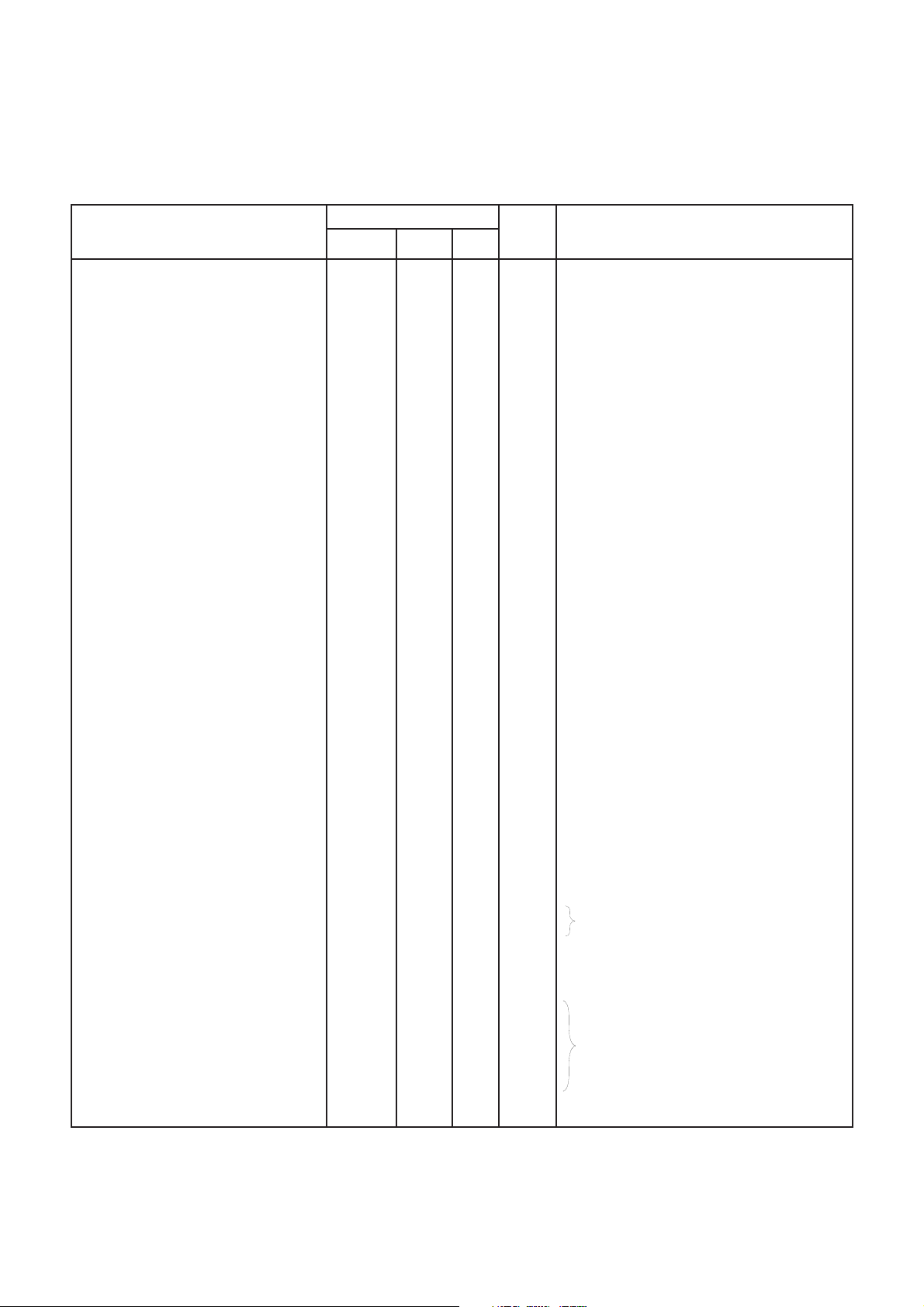
ELECTRICAL CHARACTERISTICS
The Electrical Characteristics are guaranteed over the following range of operating conditions (see Fig. 3 for test circuit):
Industrial (I) grade: T
Supply voltage: V
Test conditions (unless otherwise stated):
Supply voltages: VCC = +2.7V and +5.5V, VDD = +2.7V and +5.5V
Test temperature: Industrial (I) grade product: +25°C
= -40°C to +85°C
AMB
and VDD = +2.7V to +5.5V
CC
Characteristic
SUPPLY CURRENT
Normal mode - Analog interface
- Digital interface
Power down mode - Analog interface
- Digital interface
Power Supply Differential
Power down Response time
IF STRIP
Front End/Mixer 1
Conversion Gain (G1)
Noise Figure
Input Compression (1dB)
Input Impedance
Differential Output Impedance
RF Input Image Rejection
Stage 2/Mixer 2
Conversion Gain (G2)
Input Compression (1dB)
Differential Input Impedance
Differential Output Impedance
Min.
11
-22
22
5
Value
Typ. Max.
55
77
14.5
9
3
3
100
3
18
25
9
-16
15
3.6
700
8
27
33
14
700
500
6
5
Units
mA
mA
mA
mA
mV
µs
dB
dB
dBm
Ω
nH
Ω
dB
dB
mV rms
Ω
Ω
Conditions
Pins 5, 23, 26, 32, 35, 42
Pin 16
Pins 5, 23, 26, 32, 35, 42
Pin 16
Between any V
CC/VDD
pins (Note 7)
(Note 7)
R
= 600Ω (Note 2)
O
FIN = 1575.42MHz
Z
= 50Ω (Note 7)
S
Pin 29 (Notes 1 and 7)
(Notes 1 and 7)
Pins 33 & 34 (Note 8)
F
= 1224.58MHz (Note 7)
IN
F
= 175.42MHz
IN
Pins 36 & 37 (Note 8)
Pins 40 & 41 (Note 8)
Stage 3
High Gain (In terms of total strip)
High Gain (G3)
Gain Control Range
Differential Input Impedance
IF Output amplitude
IF Output impedance
4.3MHz Filter Response
Flatness 4.3 ± 1MHz
Rejection @ 0.5MHz
@ 50MHz
2 BIT QUANTISER
Sign Duty Cycle
Mag Duty Cycle
AGC Time Constant
ON-CHIP PLL SYNTHESISER
Phase Noise
± 1kHz
± 10kHz
± 100kHz
± 1MHz
± 5MHZ
± 50MHz
PLL Spurs
106-G1-G2
60
-1.5
45
40
20
75
60
1
85
1
14
70
50
30
2
-68
-75
-88
-110
-120
-120
-50
120
+1.0
60
40
dB
dB
dB
kΩ
mV rms
kΩ
dB
dB
dB
%
%
ms
dBc/Hz
dBc/Hz
dBc/Hz
dBc/Hz
dBc/Hz
dBc/Hz
dBc
(Note 6)
F
= 35.42MHz
IN
(Note 3)
Pins 43 & 44 (Note 8)
CW input (Note 3)
Pin 1(Note 8)
(Note 7 and 9)
(Note 10)
C
= 100nF
AGC
15kHz Loop Bandwidth
(Note 7)
(Note 7)
4
Page 5
Characteristic
Min.
Value
Typ. Max.
Units
GP2010
Conditions
VCO Maximum Lock Frequency
VCO Minimum Lock Frequency
VCO regulator output voltage
VCO Gain
Phase Detector Gain
10MHz Reference Input
10MHz Reference Input Impedance
PLL Lockup Time
PLL Loop Gain
DIGITAL INTERFACES
Sample Clock, Power Down,
Test Inputs.
V
IH
V
IL
Input Current High I
Input Current Low I
IH
IL
Sign/Mag Outputs
V
OH
V
OL
Sample Clock to Sign/Mag Delay
40MHz Clock Output
High Level (V
OH
)
Low Level (VOL)
Output (differential)
Duty Cycle
1414
3
50
0.1
2
0
-300
V
-1
DD
VDD-1.25
3.3
150
5.3
0.6
5
6
150
20
V
-1
DD
VOH-0.1
220
43
1386
3.5
240
1.2
V
DD
0.5
10
0.5
VDD-0.8
MHz
MHz
V
MHz/V
V/rad
V pk-pk
kΩ
ms
dB
V
V
µA
µA
V
V
ns
V
V
mV p-p
%
(Note 4)
(Note 7)
Pin 24
(Note 11)
From Power up (Note 7)
(Note 7)
Pins 11, 17, 18
V
= V
IH
DD
VIL = V
EE
Pins 13, 12
IO = -0.5mA
IO = 0.5mA
CL = 15pF, RL = 15kΩ (Note 7)
Pins 14 & 15
(Note 5)
CL = 15pF (GND) (Note 7)
CL = 5pF (Diff) (Note 7)
(Note 7)
LD (PLL Lock)/PReset Outputs
Low Level (V
High Level (V
OL
OH
)
)
Power-on Reset comparator input
Power Reset Reference Level
Power Reset Reference Input Current
VDD-1
1.1
-10
0.2
V
DD
0.5
1.35
10
µA
V
V
V
Pins 19 and 9
I
= 0.5mA
O
I
= -10µA
O
Pin 8
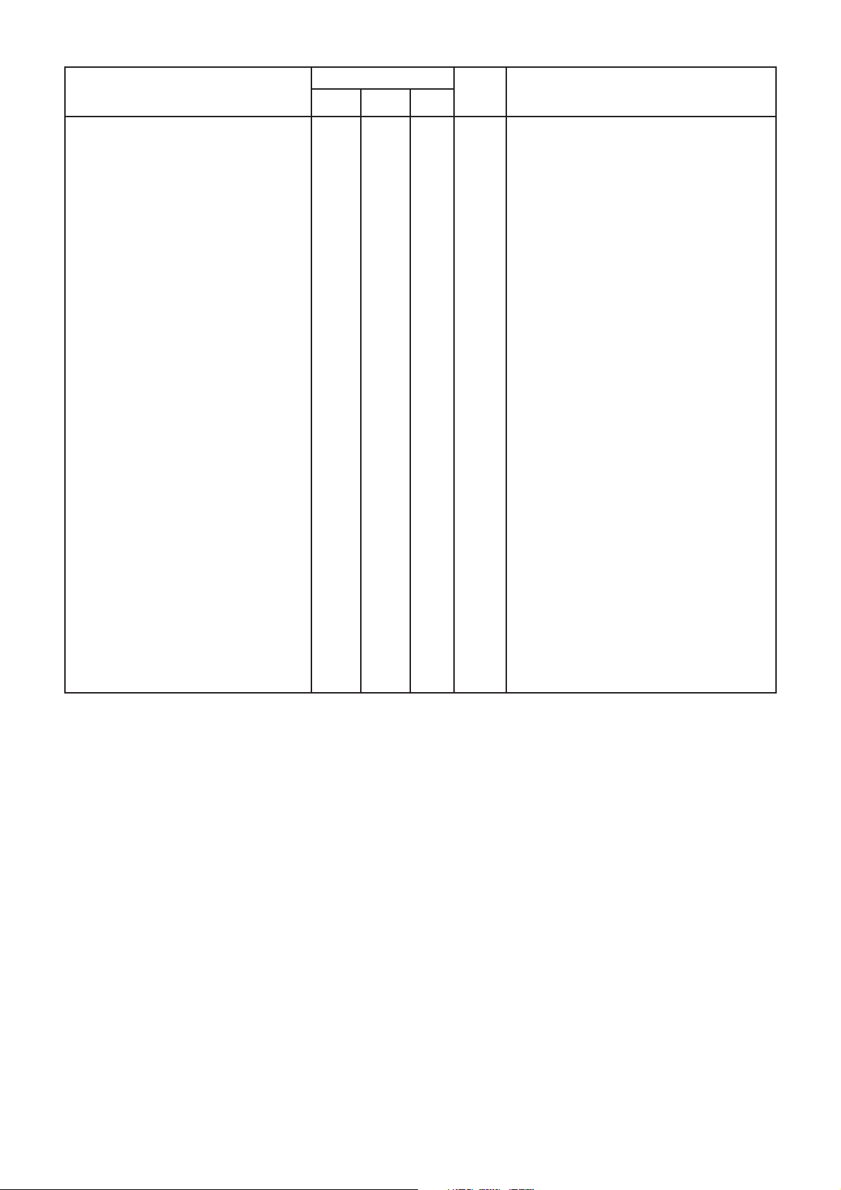
Notes On Electrical Characteristics:- All RF measurements are made with appropriate matching to the input or output
impedances, such as balun transformers, and levels refer to matched 50ohm ports (see figure 3 for test circuit)
1. RF input impedance (series) without input matching components connected - expressed as Real impedance with reactive
inductor value. Measured at 1575.42MHz.
2. Input matched to 50ohm, output loaded wlth 600ohms differential
3. Maximum Stage 3 input signal amplitude for correct AGC operation = 20mV rms.
4. VCO regulator voltage measured with respect to Vcc (OSC) - pin 5.
5. OPCLK outputs are differential and are referenced to V
DD
.
6. Minimum gain requirement expressions:
-7dBm < -174dBm/Hz + 19dB + G1 + G2 + G3 - 21dB + 63dB
where -7dBm = typical IF Output level with AGC active (equivalent to 100mV rms)
-174dBm/Hz = background noise level at RF input
19dB = sum of LNA gain and noise figure
-21dB = total loss in 175MHz and 35MHz filters
63dB = summation of noise over a 2MHz bandwidth
Rearranging the above expression gives G1 + G2 + G3 > 106dB.
7. This parameter is not production tested.
8. This impedance is toleranced at +/-30% and is not production tested.
9. Roll off occurs in on-chip capacitive coupling IF Output to input of ADC circuit. Not measurable at IF Output.
10. CW input on pins 43 & 44 of 35.42MHz at 7mV rms.
11. This input impedance applies to the typical input level. The impedance is level dependent and is not tested or guaranteed.
5
Page 6
GP2010
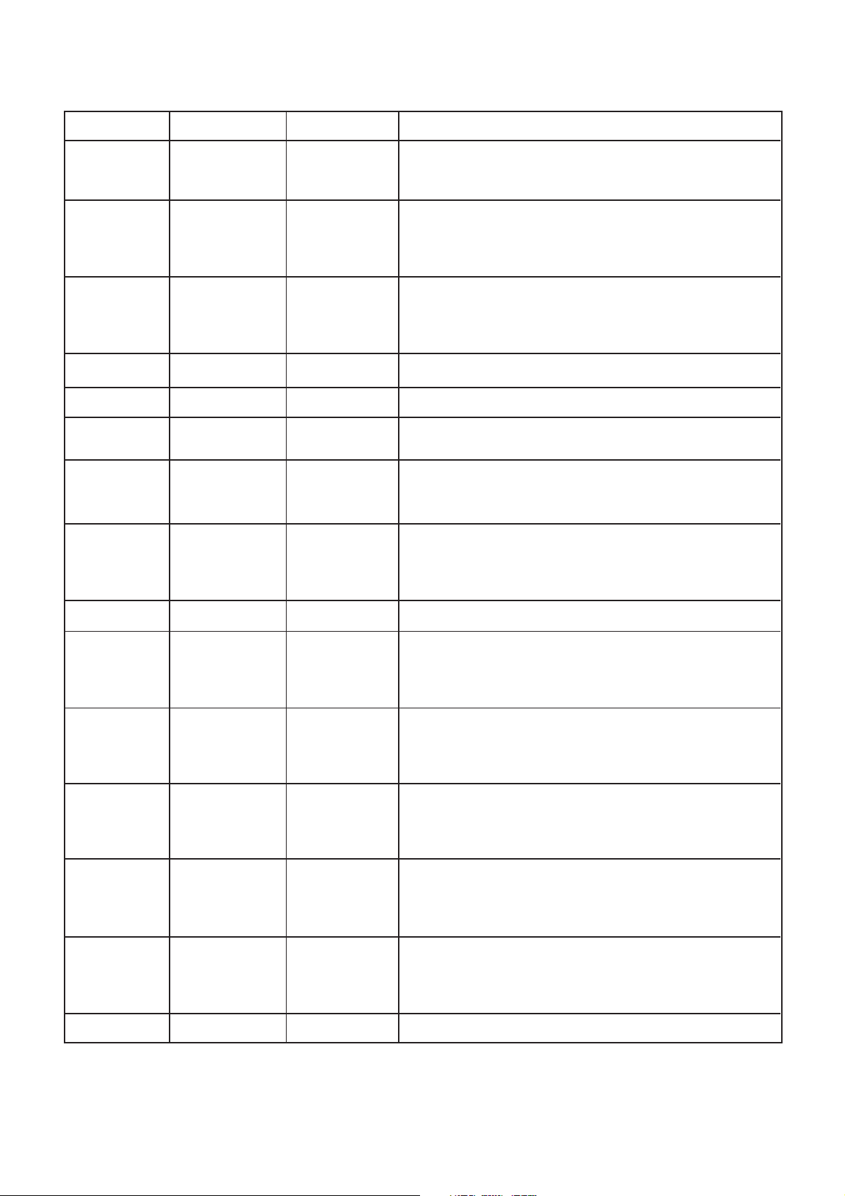
PIN DESCRIPTIONS
All VEE and VCC/VDD pins should be connected to ensure reliable operation
Pin No. Signal Name Input/Output Description
1 IFOutput Output IF Test output.
Connected to output of Stage 3 prior to the A to D converter.
A series 1kΩ resistor is incorporated for buffering purposes.
2 PLL Filt1 Output PLL Filter 1.
Connected to the bias network within the on-chip VCO. An
external PLL loop filter network should be connected between
this pin and PLL Filt 2 (see below).
3 PLL Filt2 Output PLL Filter 2.
Connected to the varactor diodes within the on-chip VCO. An
external PLL loop filter network should be connected between
this pin and PLL Filt 1 (see above).
4,6 VEE (OSC) Input Negative supply to the on-chip VCO. (See Note 1)
5V
7V
8 PRef Input Power-on Reset Reference input.
9 PReset Output Power-on Reset Output.
10 VEE (IO) Input Negative supply to the Digital Interface. (See Note 2)
11 CLK Input Sample Clock input from the correlator chip.
12 MAG Output Magnitude bit data output.
13 SIGN Output Sign bit data output.
(OSC) Input Positive supply to the on-chip VCO.
CC
(REG) Input Negative supply to the VCO regulator.
EE
This must be connected to GND.
An on-chip comparator produces a logic HI when the PRef
input voltage exceeds +1.21V. (Nom) (See Page 3).
A TTL compatible output controlled by the Power-on reset
comparator (See above). This output remains active even
when the chip is powered down. (See pin 17 - PDn).
A TTL compatible input (which operates at 5.714MHz if used
with GP2021 correlator device) used to clock the MAG & SIGN
output latches, on the rising edge of the CLK signal.
A TTL compatible signal, representing the
mixed down IF signal. Derived from the on-chip 2-bit A to D
converter, synchronised to the CLK input clock signal.
A TTL compatible signal, representing the
down IF signal. Derived from the on-chip 2-bit A to D converter,
synchronised to the CLK input clock signal.
magnitude
polarity
of the mixed
of the
14 OPClk- Output 40MHz Clock output - inverse phase.
One side of a balanced differential output clock, with opposite
polarity to Pin 15 - OPClk+. Used to drive a master-clock signal
within the correlator chip.
15 OPClk+ Output 40MHz Clock output - true phase.
Other side of a balanced differential output clock set, with
opposite polarity to Pin 14 - OPClk-. Used to drive a masterclock signal within the correlator chip.
16 VDD (IO) Input Positive supply to the Digital Interface. (See Note 2)
6
Page 7

Pin No. Signal Name Input/Output Description
17 PDn Input Power-Down control input.
A TTL compatible input, which when set to logic high, will
disable ALL of the GP2010 functions, except the power-on
reset block. Useful to reduce the total power consumption of
the GP2010. If this feature is not required, the pin should be
connected to 0V (VEE/GND).
18 TEST Input Test control input - Disable PLL.
A TTL compatible input, which when set to logic high, will
disable the on-chip PLL, by disconnecting the divided-down
VCO signal to the phase-detector. The VCO will free run at its
upper range of frequency operation. If this feature is not
required, the pin should be connected to 0V (VEE/GND).
19 LD Output PLL Lock Detect output.
A TTL compatible output, which indicates if the PLL is phaselocked to the PLL reference oscillator. Will become logic high
only when phase-lock is achieved.
20 VEE (DIG) Input Negative supply to the PLL and A to D converter.
21 AGC- Output AGC Capacitor output - inverse phase.
One side of a balanced output from the AGC block within IF
Stage 3, to which an external capacitor is connected to set the
AGC time-constant.
GP2010
22 AGC+ Output AGC Capacitor output - true phase.
One side of a balanced output from the AGC block within IF
Stage 3, to which an external capacitor is connected to set the
AGC time-constant.
23 VCC (DIG) Input Positive supply to the PLL and A to D converter.
24 REF 2 Input 10.000MHz PLL Reference signal input .
Input to which an externally generated 10.000MHz PLL
reference signal should be ac coupled, if an external PLL
reference frequency source (e.g TCXO) is used (see fig. 6).
If no external reference is used, this pin forms part of the on-
chip PLL reference oscillator, in conjunction with an external
10.000MHz crystal (see fig. 5).
25 REF 1 Input PLL reference oscillator auxillary connection.
Used in conjunction with Pin 24 (REF 2) to allow a 10.000MHz
external crystal to provide the PLL reference signal if no
external PLL reference frequency source (e.g TCXO) is used.
This pin should NOT be connected if an external TCXO is
being used (see fig. 5).
26, 32 VCC (RF) Input Positive supply to the RF input and Stage 1 IF mixer.
Both pins 26 & 32 (VCC (RF)) are connected internally, but
must both be connected to VCC externally, to keep series
inductance to a minimum.
27, 28, VEE (RF) Input Negative supply to the RF input and Stage 1 IF mixer.
30, 31 Pins 27, 28, 30 & 31 are all connected internally, but must ALL
be connected to 0V (VEE/GND) externally, to keep series
inductance to a minimum.
7
Page 8
GP2010
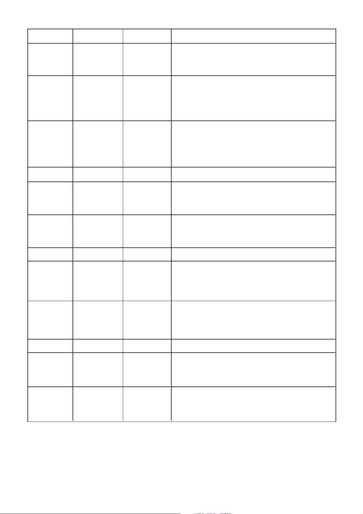
Pin No. Signal Name Input/Output Description
29 RF Input Input RF input.
The GPS RF input signal @ 1575.42MHz from an external
antenna with LNA and filter is connected to this pin via an
input-matching network (see fig.4).
33 O/P 1- Output Stage 1 mixer output @ 175.42MHz - inverse phase.
One of a balanced output from first stage IF mixer, to which
one input of an external balanced 175MHz bandpass filter is
connected. External dc biasing is required via an inductor
connected to VCC(RF) - the value of which is dependent on the
filter used.
34 O/P 1+ Output Stage 1 mixer output @ 175.42MHz - true phase.
Second of a balanced output from first stage IF mixer, to which
the second input of an external balanced 175MHz bandpass
filter is connected. External dc biasing is required via an
inductor connected to VCC(RF) - the value of which is dependent
on the filter used.
35 VCC (2) Input Positive supply to the Stage 2 IF mixer.
36 I/P 2- Input Stage 2 mixer input @ 175.42MHz - inverse phase.
One of a balanced input to the second stage IF mixer, to which
one of the balanced signal outputs from the external 175MHz
bandpass filter is connected.
37 I/P 2+ Input Stage 2 mixer input @ 175.42MHz - true phase.
Second of a balanced input to the second stage IF mixer, to
which the second of the balanced signal outputs from the
external 175MHz bandpass filter is connected.
38,39 VEE (IF) Input Negative supply to the Stage 2 IF mixer, and Stage 3 IF block.
40 O/P 2- Output Stage 2 mixer output @ 35.42MHz - inverse phase.
One of a balanced output from second stage IF mixer, to which
one input of an external balanced 35.42MHz bandpass filter is
connected. External dc biasing is required via an Inductor
connected to VCC. (See Note 3)
41 O/P 2+ Output Stage 2 mixer output @ 35.42MHz - true phase.
Second of a balanced output from second stage IF mixer, to
which the second input of an external balanced 35.42MHz
bandpass filter is connected. External dc biasing is required
via an Inductor connected to VCC. (See Note 3)
42 VCC (3) Input Positive supply to the Stage 3 IF mixer.
43 I/P 3- Input Stage 3 mixer input @ 35.42MHz - inverse phase.
One of a balanced input to the third stage IF mixer, to which
one of the balanced signal outputs from the external 35.42MHz
bandpass filter is connected. (See Note 3)
44 I/P 3+ Input Stage 3 mixer input @ 35.42MHz - true phase.
Second of a balanced input to the third stage IF mixer, to which
the second of the balanced signal outputs from the external
35.42MHz bandpass filter is connected. (See Note 3)
8
Page 9
GP2010
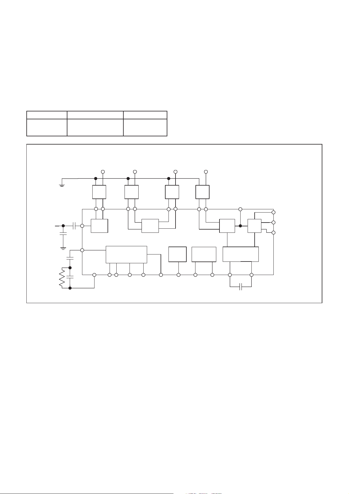
Notes on Pin Descriptions
1). Both pins 4 & 6 (V
4 & 6 must be left floating, with either pin de-coupled to VCC (OSC) with a 100nF capacitor. In this configuration, the dc output
level of the regulator can be monitored from V
V
<+4.0V, the VCO regulator cannot be used, and both VEE (OSC) pins must be shorted to VEE (REG) (Pin 7) -
CC
see Fig. 7.
2). The Digital Interface supply is independent from all the other supply pins, allowing supply separation to reduce the likelihood
of undesirable digital signals interfering with the IF strip. (Note the maximum allowable Power Supply Differential in the
Electrical Characteristics - page 4).
3). The 35.42MHz Bandpass filter should have a bandwidth of approx 2.0MHz. Ideally, this should be a DW9255 SAW filter.
CONTROL SIGNALS
Power Down Normal Operation Powered Down
TEST Normal Operation Test
(OSC)) are connected internally. If the VCO regulator is used (VCC = +5.00V nominal) then both pins
EE
(OSC), with respect to V
EE
(OSC) - NOT 0V (VEE/GND). For operation at
CC
LH
Stage 2
Input
175 MHz
M2M1
PLL
SYNTHESISER
37363433
Stage
Stage
2
2
24 18
40
RF
INPUT
PLL
LOOP
FILTER
R1
C1
Cs
Cp
Stage 1
Output
175 MHz
M1 M2 M3 M4
29
Stage
1
2
3 14 15 19
C2
OPClk LD REF 2 TEST PDn
Fig. 3 GP2010 test circuit
OPERATING NOTES
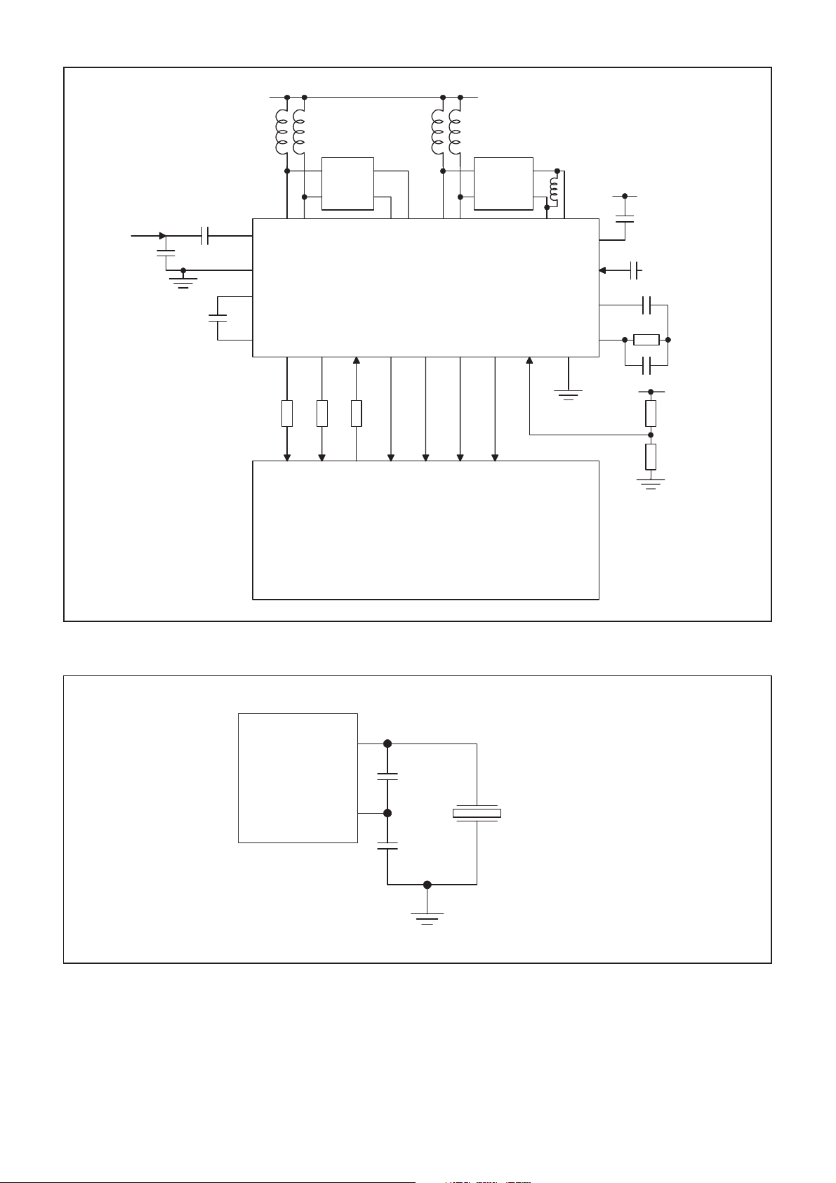
A typical application circuit is shown in figure 4 with the
GP2010 front-end interfaced to the GP2021 12 channel
correlator integrated circuit. The RF input has an unmatched
input impedance (see page 4). The RF input matching components Cs and Cp should be mounted as close to the RF
input as possible: also the Vee(RF) tracks must be kept as
short as possible. A SAW may be used as a 175.42MHz filter,
but this can be replaced by a simpler coupled-tuned LC filter
if there is no critical out-of band jamming immunity requirement. The DC bias to mixer 1 is provided via inductors L1 and
L2, which may form part of the 175.42MHz filter. The output
of mixer 2 requires an external dc bias, achieved with inductors
L3 and L4, which also serve to tune out the input capacitance
of the DW9255 SAW filter. The output of the SAW is tuned with
inductor L5. The AGC capacitor (Cagc) determines the AGC
time-constant. The PLL loop filter components are selected to
give a PLL loop bandwidth of approx. 10kHz. The IF Output
is normally used for test-purposes only, but is available to the
user if required. Typically a low noise preamplifier (gain
>+15dB) is used, and may be located with a remote antenna.
Stage 2
Output
35 MHz
Power
Down
17
Stage 3
Input
35 MHz
M4M3
444341
Power
Detect
98
PRESET PREF
M1 - 4 = Matching
Networks, incorporating
Balun transformers
IF
Output
1
Stage
Stage
3
3
AGC Control
AGC Control
21
ADC
22
Cagc
CLK
11
SIGN
13
MAG
12
C1 = 470nF
C2 = 10nF
R1 = 270Ω
Cagc = 100nF
Cs = 5pF
Cp = 1.5pF
QUALITY AND RELIABILITY
At Mitel Semiconductor, quality and reliability are built
into products by rigorous control of all processing operations,
and by minimising random, uncontrolled effects in all manufacturing operations. Process management involves full documentation of procedures, recording of batch-by-batch data,
using traceability procedures, and the provision of appropriate equipment and facilities to perform sample screening and
conformance testing on finished product.
A common information management system is used to
monitor the manufacturing on Mitel Semiconductor CMOS
and Bipolar processes. All products benefit from the use of an
integrated monitoring system throughout all manufacturing
operations, leading to high quality standards for all technologies.
Further information is contained in the Quality Brochure, available from Mitel Semiconductor Sales Offices.
9
Page 10
GP2010
VALUES FOR L1 AND L2 ARE
DEPENDENT ON FILTER USED
RF INPUT
MATCHING
Cs = 4.7pF
Cp = 1.5pF
RF
INPUT
Cs
Cp
Cagc
=0.1uF
R4, R5 = 470Ω
R6 = 1.5kΩ
Vcc
L3,4 = 560nH
L5 = 2.2uH
MAG 0
L4
DW9255
FILTER
PLL LOCK
SAW
2667776737170
POWER_GOOD
L3L1 L2
175MHz
FILTER
33 34 36 37 40 41 43 44
29
27,28,
30,31
21
22
15 14 11
CLK_T
GP2010 FRONT-END
44 PIN
13 12 19 9
SAMP CLK
CLK_I
SIGN 0
L5
4, 6
24
2
818
POWER-ON REF
3
Vcc
Creg = 0.1uF
(Vcc = +5.0V only)
REF2
10MHz I/P
C1
R1
C2
Vcc
R2R4 R5 R6
R3
PLL LOOP
FILTER
C1 = 0.47uF
R1 = 270Ω
C2 = 10nF
NOTE:
DIAGRAM IS REPRESENTATIVE
ONLY. REFER TO AN4364
FOR ACTUAL CIRCUIT
GP2010
GP2021 CORRELATOR
80 PIN
Fig. 4 GP2010 typical application
Ref 2
(24)
33pF
(25)
Ref 1
22pF
POWER-ON
REF
LADDER
R3 =2.7k
R2 = 2.7k (Vcc = +3.0V)
= 6.8k (Vcc = +5.0V)
10.000MHz
CRYSTAL
10
Fig. 5 Crystal Reference connections
Page 11
GP2010
GP2010
V
(5)
GP2010
CCOSC
(4)
(6)
Ref 2
(24)
(25)
Ref 1
3V
47nF
RA
RB
NC
Fig. 6 TCXO Reference connections
V
EEOSC
10.000MHz
TCXO
RA & RB SET TO REDUCE TCXO
O/P TO REQUIRED LEVEL
5V
V
CCOSC
(5)
(4)
V
GP2010
EEOSC
(6)
100nF
(7)
V
EEREG
0V
No VCO Regulator needed
Using VCO regulator with Vcc > +4.0V
Fig. 7 VCO power-supply connections
(7)
V
EEREG
0V
11
Page 12
GP2010
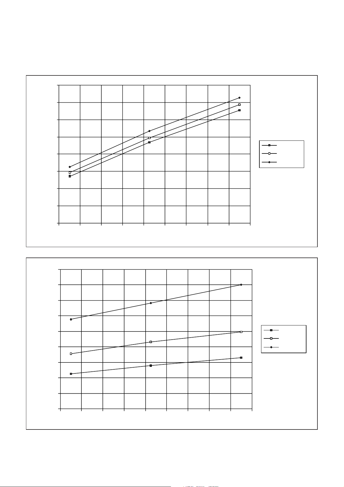
TYPICAL CHARACTERISTICS OF THE GP2010 GPS RECEIVER RF FRONT-END
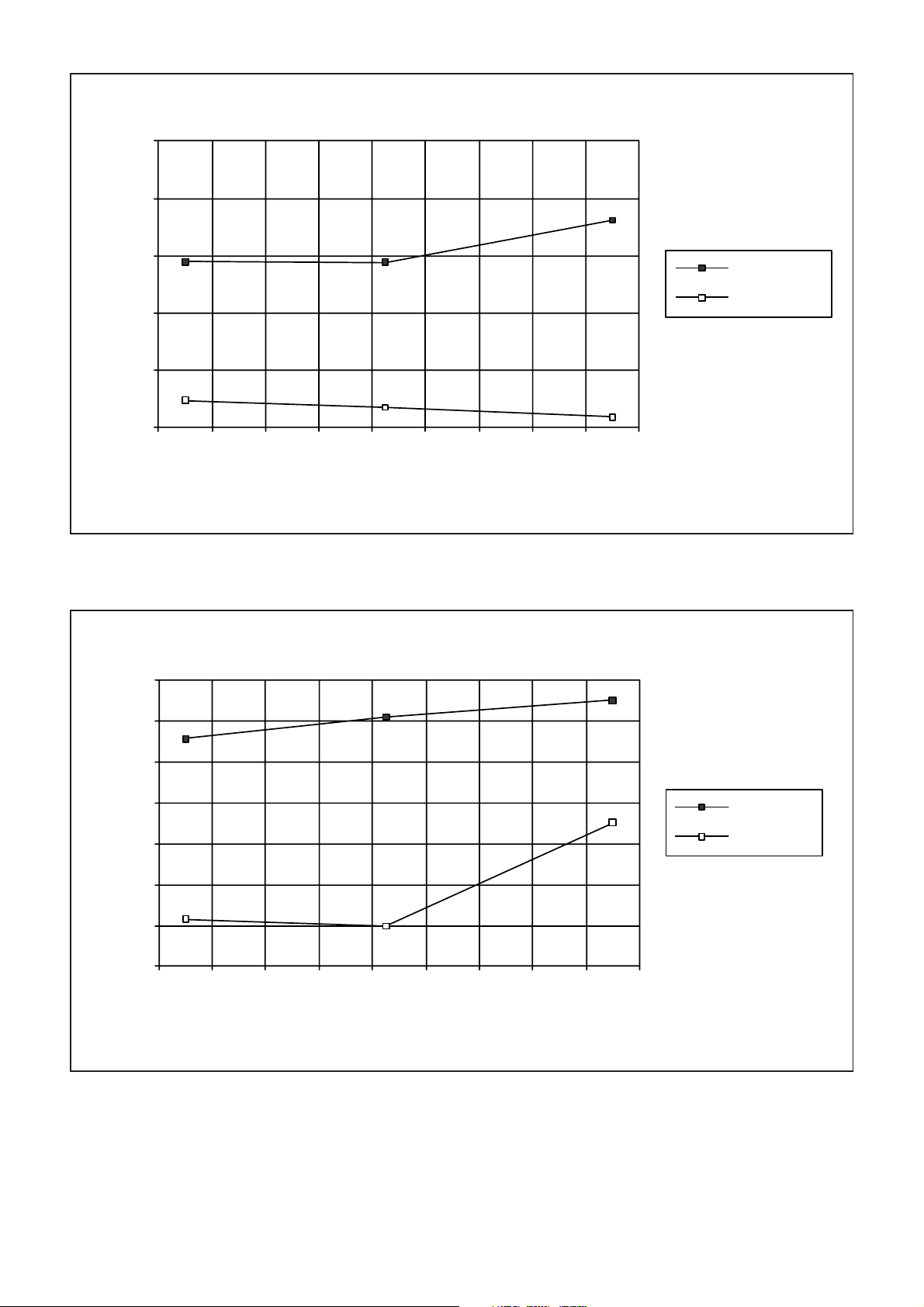
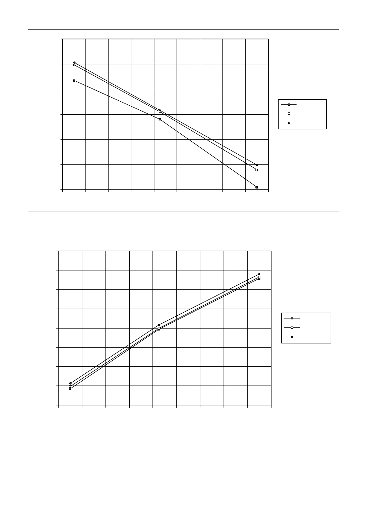
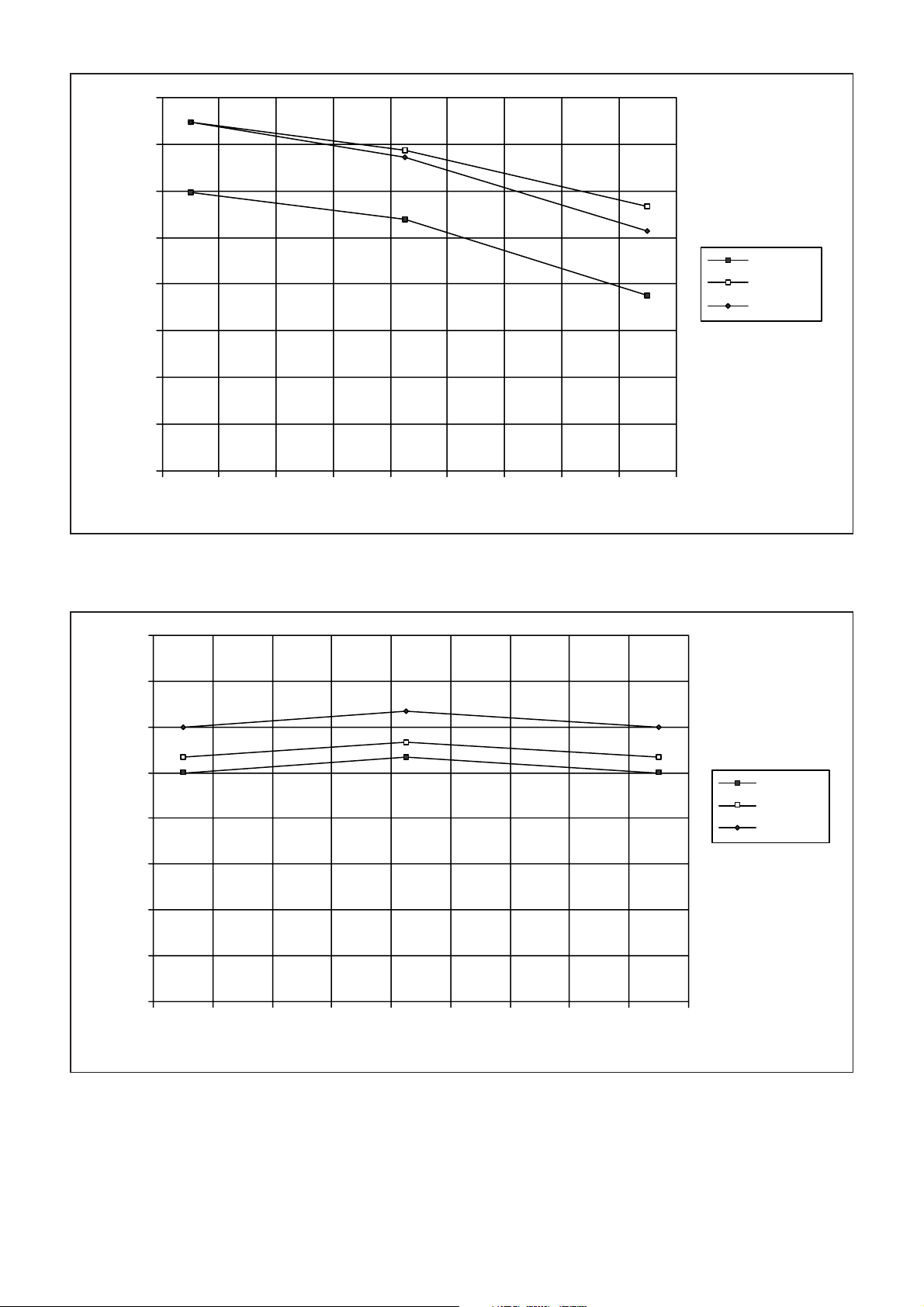
The GP2010 has been characterised to guarantee reliable operation over the Industrial Temperature range (-40°C -> +85°C
ambient). This was achieved by setting the device case temperature to extremes of +110°C and -50°C.
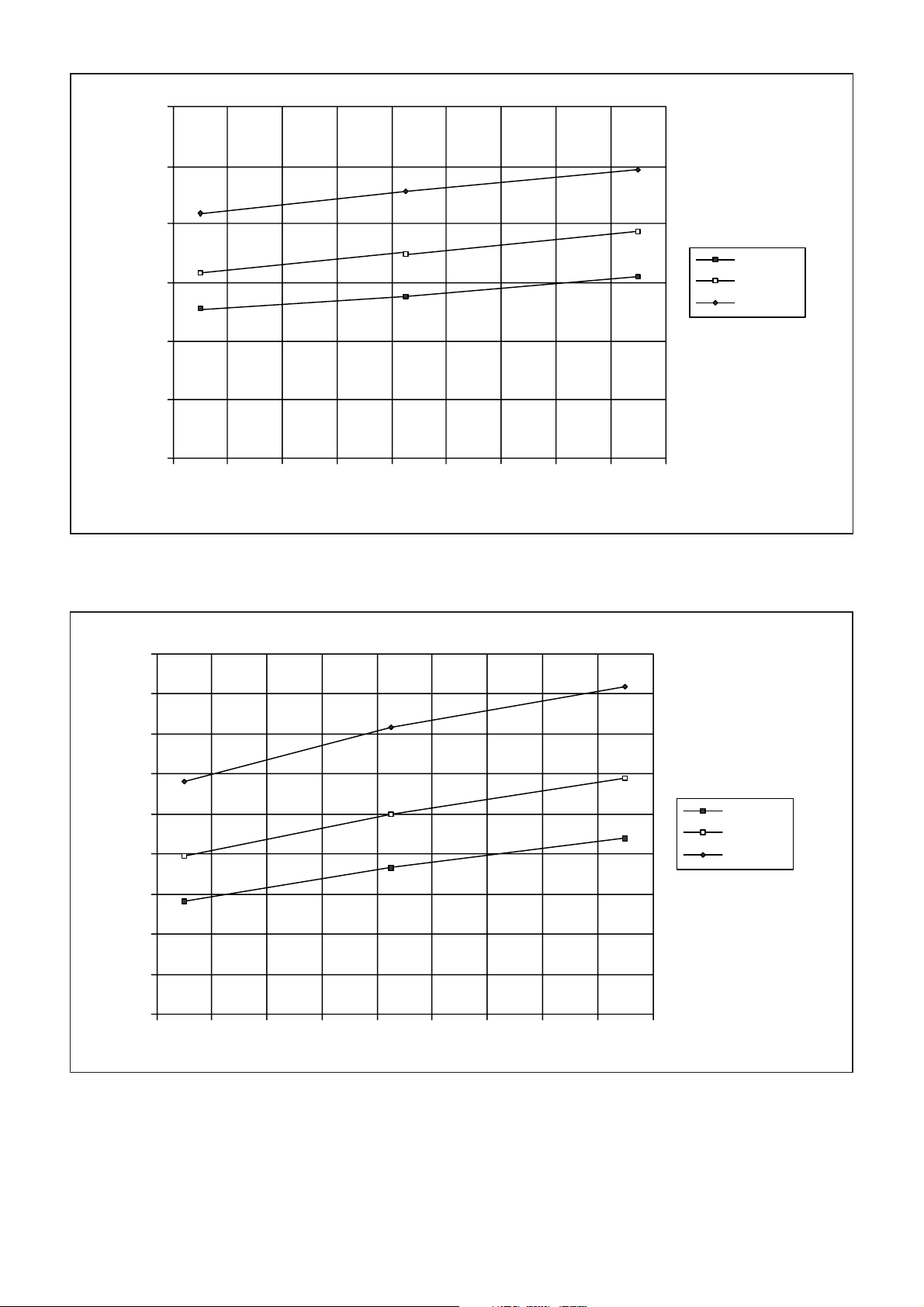
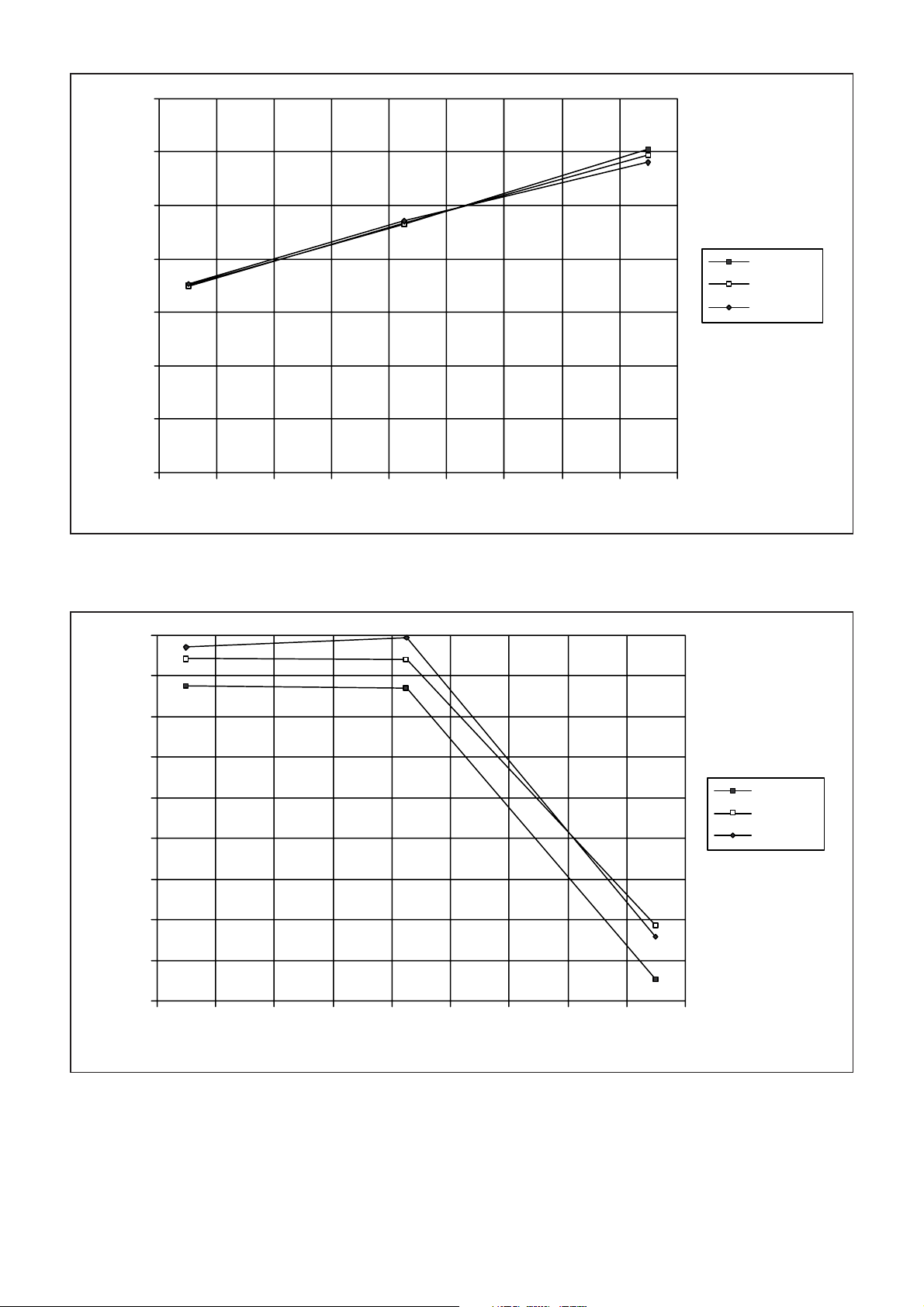
The following charts show the typical variation of key parameters across the extended case temperature range.
NOTE:-
ALL Measurements at Vcc = +2.65V made with VCO voltage-regulator
70
65
60
55
50
CURRENT (mA)
45
40
35
30
-60 -40 -20 0 20 40 60 80 100 120
CASE TEMP(°C)
DISABLED.
Vcc = +2.65V
Vcc = +3.8V
Vcc = +5.55V
Fig. 8 Supply Current - Analog interface - normal mode
4.5
4
3.5
3
2.5
2
CURRENT (mA)
1.5
1
0.5
0
-60 -40 -20 0 20 40 60 80 100 120
CASE TEMP(°C)
Vcc = +2.65V
Vcc = +3.8V
Vcc = +5.55V
12
Fig. 9 Supply Current - Analog interface - power-down mode
Page 13
12
10
8
6
CURRENT (mA)
4
2
0
-60 -40 -20 0 20 40 60 80 100 120
CASE TEMP(°C)
GP2010
Vcc = +2.65V
Vcc = +3.8V
Vcc = +5.55V
4.5
4
3.5
3
2.5
2
CURRENT (mA)
1.5
1
0.5
Fig. 10 Supply Current - Digital interface - normal mode
Vcc = +2.65V
Vcc = +3.8V
Vcc = +5.55V
0
-60 -40 -20 0 20 40 60 80 100 120
CASE TEMP(°C)
Fig. 11 Supply Current - Digital interface - power-down mode
13
Page 14
GP2010
14
12
10
8
6
NOISE FIGURE (dB)
4
2
0
-60 -40 -20 0 20 40 60 80 100 120
CASE TEMP (°C)
Fig. 12 Noise figure of IF chain in a typical application circuit
151
150.5
Vcc = +2.65V
Vcc = +3.8V
Vcc = +5.55V
150
149.5
149
148.5
LOOP GAIN (dB)
148
147.5
147
146.5
-60 -40 -20 0 20 40 60 80 100 120
Vcc = +2.65V
Vcc = +3.8V
Vcc = +5.55V
CASE TEMP(°C)
Fig. 13 On-chip Phase-locked-loop Synthesiser Loop gain
14
Page 15
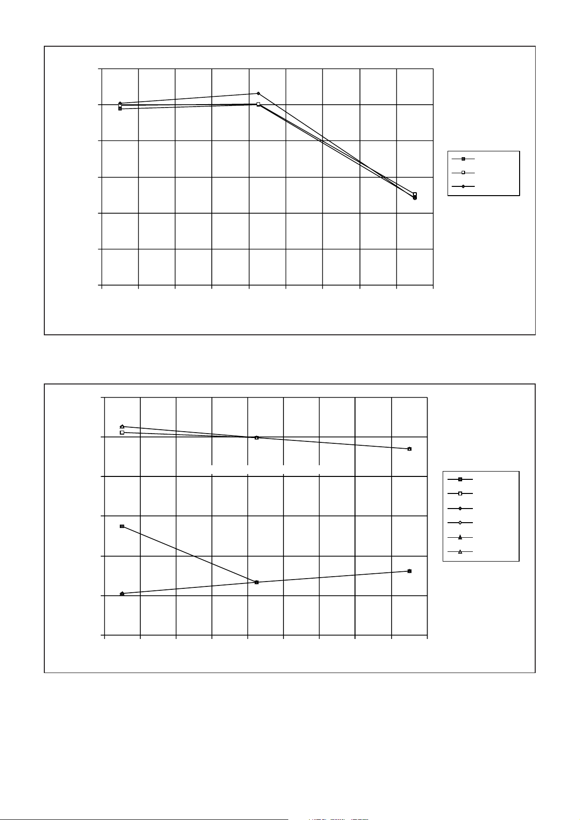
6
5.5
5
4.5
4
PHASE-DETECTOR GAIN (V/radian)
3.5
3
-60 -40 -20 0 20 40 60 80 100 120
CASE TEMP(°C)
GP2010
Vcc = +2.65V
Vcc = +3.8V
Vcc = +5.55V
1600
1500
1400
1300
VCO FREQUENCY (MHz)
1200
1100
Fig. 14 On-chip Phase-locked-loop Synthesiser Phase-detector gain
NOTE:- 1400MHz is the nominal VCO frequency
LOW - 2.65V
HIGH - 2.65V
LOW - 3.8V
HIGH - 3.8V
LOW - 5.55V
HIGH - 5.55V
1000
-60 -40 -20 0 20 40 60 80 100 120
CASE TEMP(°C)
Fig. 15 On-chip Phase-locked-loop Synthesiser - LOW and HIGH limits of VCO frequency for PLL to be locked
(Note that this a typical characteristic and cannot be guaranteed)
15
Page 16
GP2010
-65
-70
-75
-80
PHASE NOISE (dBc/Hz)
-85
-90
-60 -40 -20 0 20 40 60 80 100 120
CASE TEMP (°C)
10kHz OFFSET
100kHz OFFSET
NOTE:
Vcc = +5.55V for
each offset
Fig. 16 On-chip Phase-locked-loop Synthesiser - Phase-noise of VCO producing 1400MHz CW signal at 10kHz offset
(15kHz PLL loop bandwidth)
-110
-112
-114
-116
-118
-120
PHASE NOISE (dBc/Hz)
-122
-124
-60 -40 -20 0 20 40 60 80 100 120
CASE TEMP (°C)
1MHz OFFSET
5MHz OFFSET
NOTE:
Vcc = +5.55V for
each offset
Fig. 17 On-chip Phase-locked-loop Synthesiser - Phase-noise of VCO producing 1400MHz CW signal at 100kHz offset
(15kHz PLL loop bandwidth)
16
Page 17
19.5
19
18.5
18
GAIN (dB)
17.5
17
16.5
GP2010
Vcc = +2.65V
Vcc = +3.8V
Vcc = +5.55V
-60 -40 -20 0 20 40 60 80 100 120
CASE TEMP (°C)
Fig. 18 Frontend/Mixer 1 Small-signal Conversion Gain - RF I/P frequency at 1575.42MHz
-12
-13
-14
-15
-16
-17
INPUT LEVEL (dBm)
-18
-19
Vcc = +2.65V
Vcc = +3.8V
Vcc = +5.55V
-20
-60 -40 -20 0 20 40 60 80 100 120
CASE TEMP (°C)
Fig. 19 Frontend/Mixer 1 Input level for 1dB Conversion Gain-compression - RF I/P frequency at 1575.42MHz
17
Page 18
GP2010
9
8.5
8
7.5
7
6.5
RF I/P IMAGE-REJECTION (dB)
6
5.5
5
-60 -40 -20 0 20 40 60 80 100 120
Vcc = +2.65V
Vcc = +3.8V
Vcc = +5.55V
CASE TEMP (°C)
28
27.5
27
26.5
26
GAIN (dB)
25.5
25
24.5
Fig. 20 Frontend/Mixer 1 Image rejection - RF I/P frequency at 1224.58MHz
Vcc = +2.65V
Vcc = +3.8V
Vcc = +5.55V
18
24
-60 -40 -20 0 20 40 60 80 100 120
CASE TEMP(°C)
Fig. 21 Stage 2/Mixer 2 Small-signal Conversion Gain - Stage 2 I/P frequency at 175.42MHz
Page 19
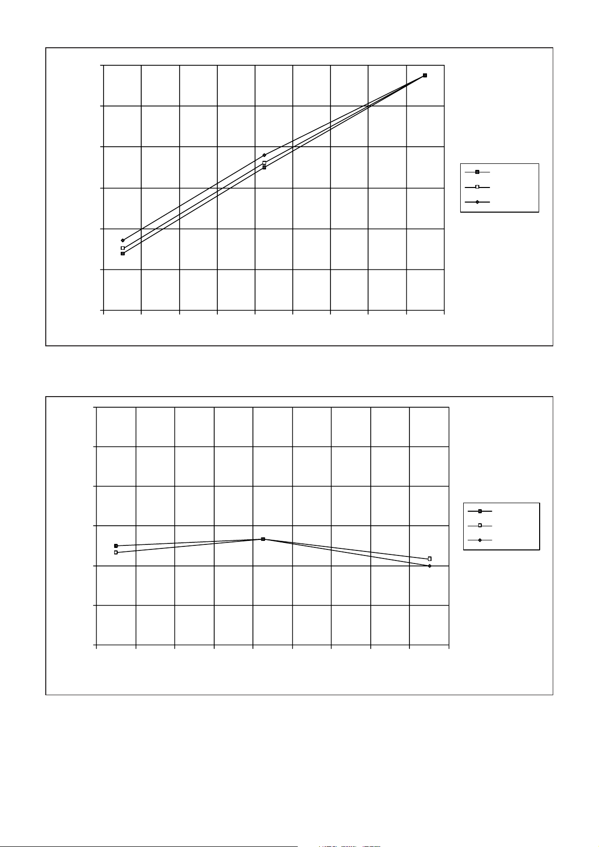
20
18
16
14
INPUT LEVEL (mV RMS)
12
10
8
-60 -40 -20 0 20 40 60 80 100 120
CASE TEMP (°C)
GP2010
Vcc = +2.65V
Vcc = +3.8V
Vcc = +5.55V
Fig. 22 Stage 2/Mixer 2 Input level for 1dB Conversion Gain-compression - Stage 2 I/P frequency at 175.42MHz
80
79
78
Vcc = +2.65V
77
GAIN (dB)
76
75
74
-60 -40 -20 0 20 40 60 80 100 120
CASE TEMP(°C)
Vcc = +3.8V
Vcc = +5.55V
Fig. 23 Stage 3 MAXIMUM Small-signal Conversion Gain - Stage 3 I/P frequency at 35.42MHz
19
Page 20
GP2010
PREF VOLTAGE (V)
1.255
1.25
1.245
1.24
1.235
1.23
1.225
1.22
1.215
-60 -40 -20 0 20 40 60 80 100 120
CASE TEMP (°C)
Vcc = +2.65V
Vcc = +3.8V
Vcc = +5.55V
32
31.5
31
30.5
30
DUTY CYCLE (%)
29.5
29
28.5
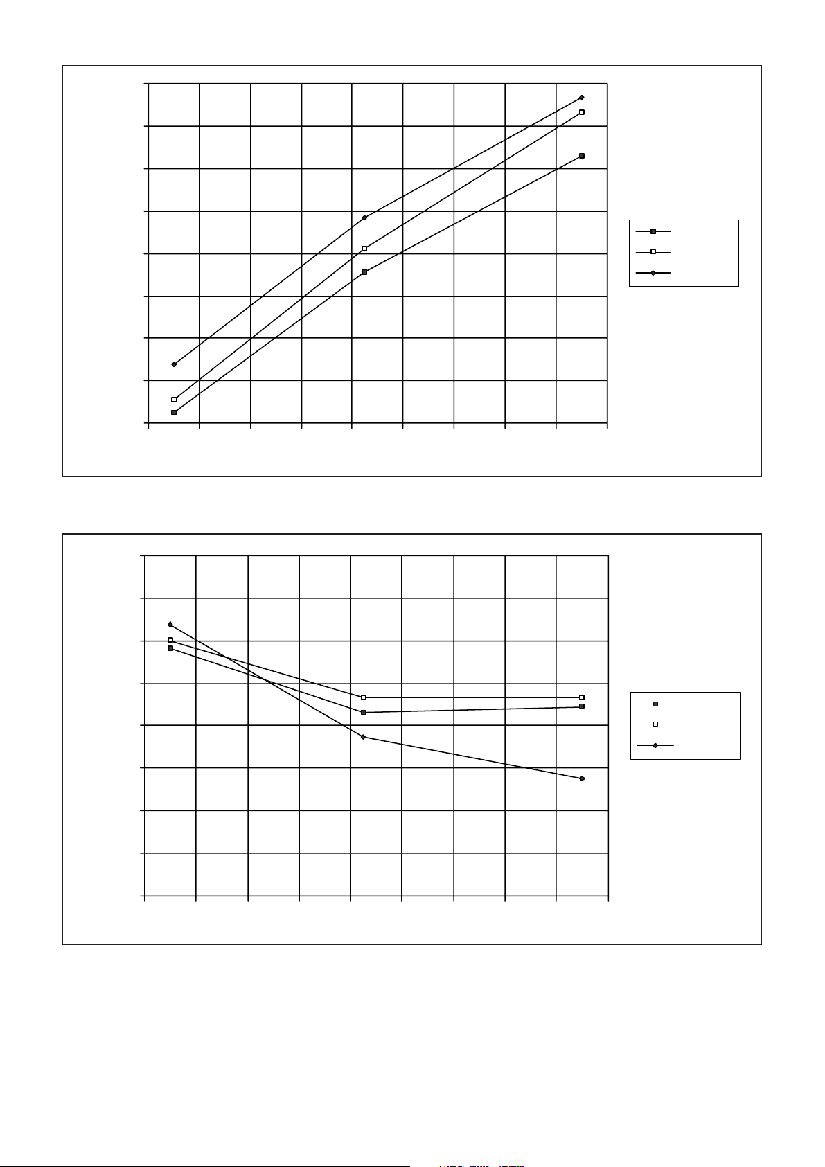
Fig. 24 Power-on Reset Threshold level
Vcc = +2.65V
Vcc = +3.8V
Vcc = +5.55V
20
28
-60 -40 -20 0 20 40 60 80 100 120
CASE TEMP(°C)
Fig. 25 Duty-cycle of MAG digital output (pin 12), sampled at 5.71MHz in a typical application circuit -
RF I/P signal = 1575.42MHz CW, -85dBm - equivalent to 26dB
excess noise from a typical GPS antenna
Page 21
50.5
50.45
50.4
50.35
GP2010
50.3
50.25
50.2
DUTY CYCLE (%)
50.15
50.1
50.05
50
-60 -40 -20 0 20 40 60 80 100 120
CASE TEMP(°C)
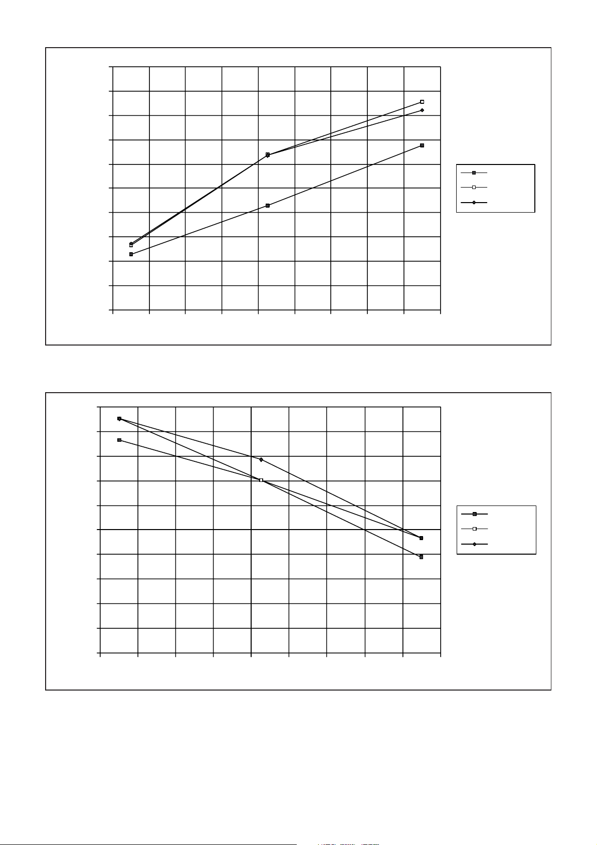
Fig. 26 Duty-cycle of SIGN digital output (pin 13), sampled at 5.71MHz in a typical application circuit
- RF I/P signal = 1575.42MHz CW, -85dBm - equivalent to
26dB excess noise from a typical GPS antenna
90
88
Vcc = +2.65V
Vcc = +3.8V
Vcc = +5.55V
86
84
82
80
78
AMPLITUDE (mV RMS)
76
74
72
70
-60 -40 -20 0 20 40 60 80 100 120
CASE TEMP(°C)
Fig. 27 Amplitude of IFOUT (pin 1) at 4.3MHz (±1.0MHz) in a typical application circuit
- RF I/P signal = 1575.42MHz CW, -85dBm - equivalent to
26dB excess noise from a typical GPS antenna
Vcc = +2.65V
Vcc = +3.8V
Vcc = +5.55V
21
Page 22
GP2010
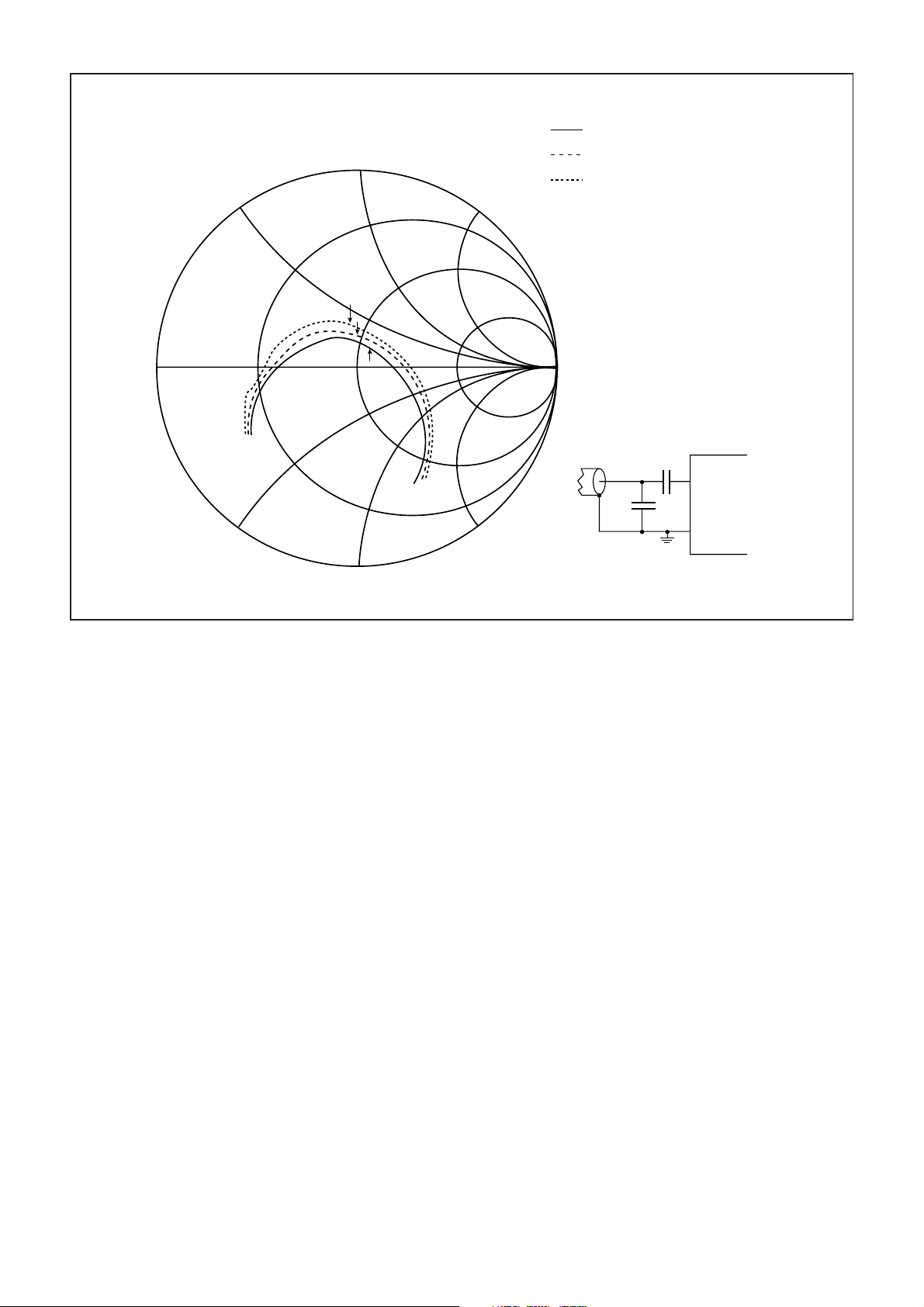
IMPEDANCE AT
1575.42MHz
1
1
j
2
3
0.5
j
3
2
3
j
+110°C
+25°C
-50°C
55.1 + j10.1 ohms
47.3 + j15.3 ohms
42.3 + j17.7 ohms
0
0.3 1 3
0.5
-j
1
3
-j
1
-j
∞
50 OHM
LINE
FROM
RF FILTER
1.5pF
4.7pF
RF INPUT
(29)
GP2010
VEE
(27, 28, 30, 31)
Fig. 28 Typical Matched RF I/P Impedance between 1000MHz and 2000MHz RF I/P level @ -40dBm
22
Page 23
Page 24

http://www.mitelsemi.com
World Headquarters - Canada
Tel: +1 (613) 592 2122
Fax: +1 (613) 592 6909
North America Asia/Pacific Europe, Middle East,
Tel: +1 (770) 486 0194 Tel: +65 333 6193 and Africa (EMEA)
Fax: +1 (770) 631 8213 Fax: +65 333 6192 Tel: +44 (0) 1793 518528
Fax: +44 (0) 1793 518581
Information relating to products and services furnished herein by Mitel Corporation or its subsidiaries (collectively “Mitel”) is believed to be reliable. However, Mitel assumes no
liability for errors that may appear in this publication, or for liability otherwise arising from the application or use of any such information, product or service or for any infringement of
patents or other intellectual property rights owned by third parties which may result from such application or use. Neither the supply of such information or purchase of product or
service conveys any license, either express or implied, under patents or other intellectual property rights owned by Mitel or licensed from third parties by Mitel, whatsoever.
Purchasers of products are also hereby notified that the use of product in certain ways or in combination with Mitel, or non-Mitel furnished goods or services may infringe patents or
other intellectual property rights owned by Mitel.
This publication is issued to provide information only and (unless agreed by Mitel in writing) may not be used, applied or reproduced for any purpose nor form par t of any order or
contract nor to be regarded as a representation relating to the products or services concerned. The products, their specifications, services and other information appearing in this
publication are subject to change by Mitel without notice. No warranty or guarantee express or implied is made regarding the capability, performance or suitability of any product or
service. Information concerning possible methods of use is provided as a guide only and does not constitute any guarantee that such methods of use will be satisfactory in a specific
piece of equipment. It is the user’s responsibility to fully determine the performance and suitability of any equipment using such information and to ensure that any publication or
data used is up to date and has not been superseded. Manufacturing does not necessarily include testing of all functions or parameters. These products are not suitable for use in
any medical products whose failure to perform may result in significant injury or death to the user. All products and materials are sold and services provided subject to Mitel’s
conditions of sale which are available on request.
M Mitel (design) and ST-BUS are registered trademarks of MITEL Corporation
Mitel Semiconductor is an ISO 9001 Registered Company
Copyright 1999 MITEL Corporation
All Rights Reserved
Printed in CANADA
TECHNICAL DOCUMENTATION - NOT FOR RESALE
 Loading...