

Page 1
GL390/GL390V
GL390/GL390V
Thin Bow Type Resin Mold
Package Infrared Emitting Diodes
■
Features
1. Thin bow type resin mold package
(Resin area : 2.0 x3.1 x 5.2 mm)
2. Low peak forward voltage (GL390V)
FM : TYP. 1.9V at IFM=0.5A
V
■
Applications
1. Cameras
2. Infrared remote controllers
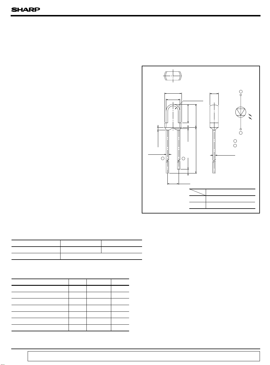
Outline Dimensions
■
± 0.3
φ 3.8
φ 3.1
MAX.
Protruded resin
0.8
± 0.1
2 - 0.5
(
2.54
* Tolerance : ± 0.2mm
❈ 1
Epoxy resin
4.1
+ 0.5
21
)
(
)
GL390
GL390V
1.0
2.0
± 0.3
5.2
- 0.2
0.2
MIN.
24.0
Pale blue transparent resin
(Unit : mm)
+ 0.1
- 0.3
2 - 0.5
❈ 1 Resin type
Blue transparent resin
1 Anode
2 Cathode
± 0.1
1
2
■
Model Lineup
Model
Radiant intensity (mW/sr)
Half intensity angle (˚ )
Absolute Maximum Ratings
■
GL390 GL390V
TYP. 13 TYP. 16
TYP. ± 18
(Ta=25˚C)
Parameter Symbol Rating Unit
Forward current
*1
Peak forward current
Reverse voltage
Power dissipation
Operating temperature
Storage temperature
*2
Soldering temperature
*1 Pulse width <=100µ s, Duty ratio=0.01
*2 For 3 seconds at the position of 2.6 mm from the resin edge
“ In the absence of confirmation by device specification sheets, SHARP takes no responsibility for any defects that occur in equipment using any of SHARP's devices, shown in catalogs,
data books, etc. Contact SHARP in order to obtain the latest version of the device specification sheets before using any SHARP's device.”
I
F
I
FM
V
R
P 150 mW
T
opr
T
stg
T
sol
60 mA
1A
6V
-25to 85
-40to 85
˚C
˚C
260 ˚C
Page 2
GL390/GL390V
Electro-optical Characteristics
■
Parameter Symbol Conditions MIN. TYP. MAX. Unit
Forward voltage
Peak forward voltage
GL390
GL390V - 1.9 3.0
Reverse current
*3
Radiant intensity
GL390
GL390V 916-
Peak emission wavelength
Half intensity wavelength
Terminal capacitance
GL390
GL390V -50
Response frequency
Half intensity angle
*3 IE: Value obtained by converting the value in power of radiant fluxes emitted at the solid angle of 0.01 sr (steradian) in the direction of mechanical axis of
the lens portion into 1 sr or all those emitted from the light emitting diode.
V
F
V
FM
I
R
I
E
λ
P
∆λ
C
t
f
c
∆
θ I
IF= 50mA 1.3 1.5 V
IFM= 0.5A
VR=3V - - 10 µA
IF= 50mA
I
= 5mA - 950 - nm
F
= 5mA
I
F
VR= 0 f= 1MHz
= 20mA - ± 18 - ˚
F
-
-
2.2 3.5
713-
-45-
-70-
- 300 - kHz
(Ta=25˚C)
-
V
mW/sr
nm
pF
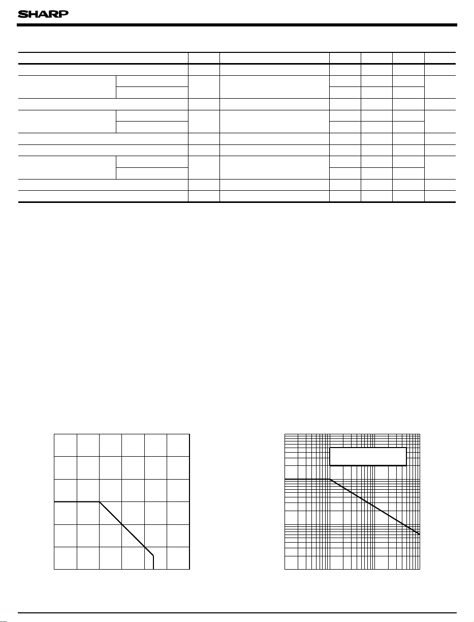
Fig. 1 Forward Current vs. Ambient
Temperature
120
100
)
mA
(
80
F
60
40
Forward current I
20
0
- 25 0 25 50 75 85 100 125
Ambient temperature Ta (˚C
Fig. 2 Peak Forward Current vs. Duty Ratio
10000
5000
)
mA
(
FM
1000
500
100
50
Peak forward current I
10
-3
10
)
Pulse width<=100µs
Ta= 25˚C
-2
10
Duty ratio
-1
10
1
Page 3

GL390/GL390V
Fig. 3 Spectral Distribution Fig. 4 Peak Emission Wavelength vs.
100
80
60
40
20
Relative radiant intensity (%)
0
880 900 920 940 960 980
Wavelength λ (nm)
I
= 5mA
F
Ta= 25˚C
1000 1020 1040
Ambient Temperature
1000
975
950
925
Peak emission wavelength λp (nm)
900
-25
025
Ambient temperature Ta ( ˚C )
IF= const.
50 75 100
Fig. 5-1 Forward Current vs. Forward Voltage Fig. 5-2 Forward Current vs. Forward Voltage
500
Ta= 75˚C
200
)
mA
(
F
100
50
20
10
5
50˚C
25˚C
0˚C
- 20˚C
Forward current I
2
1
0
0.5 1.0 1.5 2.0 2.5
Forward voltage V
3.0
)
(V
F
Fig. 6 Relative Radiant Flux vs. Ambient
Temperature
(GL390)
20
10
5
2
1
0.5
Relative radiant flux
0.2
0.1
-25
0255075100
Ambient temperature Ta ( ˚C)
IF=
const.
1000
+50˚C
)
mA
(
F
100
10
+85˚C
Forward current I
1
3.5
0 0.5 1.0 1.5 2.0 2.5 3.0
Forward voltage V
Fig. 7 Radiant Intensity vs. Forward Current
1000
Ta=25˚C
Pulse width 100µs
Duty ratio=0.01
)
100
mW/sr
(
E
10
1
0.1
Radiant intensity I
0.01
0.1 10 100 10001
:DC
: Pulse
Forward current I
+25˚C
GL390V
GL390
(GL390V)
0˚C
- 25˚C
)
(V
F
)
(mA
F
Page 4

GL390/GL390V
Fig. 8-1 Radiation Diagram (Horizontal Direction) Fig. 8-2 Radiation Diagram (Vertical Direction)
- 20˚ - 10˚ 0˚0+ 10˚ + 20˚
- 40˚ + 40˚- 30˚ + 30˚- 20 ˚ + 20˚- 10˚ + 10˚ 0˚
- 30˚
- 40˚
- 50˚
- 60˚
- 70˚
- 80˚
- 90˚
Relative radiant intensity (%)
+ 30˚
+ 40˚
+ 50˚
+ 60˚
+ 70˚
+ 80˚
+ 90˚
Angular displacement θ
Please refer to the chapter "Precautions for Use". (Page 78 to 93)
●
- 50˚
- 60˚
- 70˚
- 80˚
- 90˚
Relative radiant intensity (%)
0
Angular displacement θ
+ 50˚
+ 60˚
+ 70˚
+ 80˚
+ 90˚
 Loading...