

Page 1
1
SWITCH FOR TV, VCR
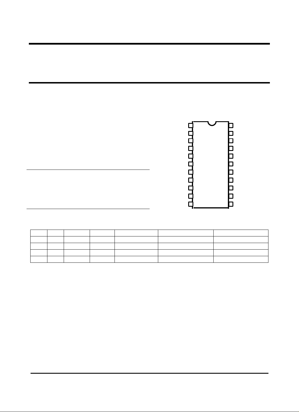
2 3 4 5 6 7 10 9 8 11 22
20
18 17 16 13 14 15 12
Functions Pin Configuration
• Audio Signal Switching
• Video Signal Switching
• Input Signal Selecting Logic
Features
•
Possible to Switch 4 Channel Video Signals
•
Possible to Switch 4 Channel L & R Audio Signals
Absolute Maximum Ratings ( CT
V Supply Voltage
Power Dissipation
Operating Temperature
Storage Temperature
1CC
V
2CC
P 310mW
D
T -20 to C°70+
OPR
T -55 to
STG
A
°= 25 )
15V
AUDIO-IN LCH(V1)
AUDIO-IN, LCH(V2)
AUDIO-IN, LCH(V3)
AUDIO-IN, RCH(V2)
AUDIO-IN, RCH(V3)
C°125+
AUDIO-IN, RCH(V1)
VIDEO-IN(V1)
V
CC
VIDEO-IN(V2)
GND
MODE-IN(C0)
1
GL3812
GL3812
GL3812
AUDIO/VIDEO
AUDIO-IN, LCH(TV)
21
AUDIO-IN, RCH(TV)
V
CC2
19
VIDEO-IN(TV)
AUDIO-OUT LCH
AUDIO-OUT RCH
VIDEO-OUT
MODE-OUT TV/LOW
MODE-OUT, V3/HIGH
MODE-IN(C1)
VIDEO-IN(V3)
Mode Selection Logic/Output Signal
C1 C0 PIN 14 PIN15 PIN 16 PIN 17 PIN 18
L L L L VIDEO (TV) AUDIO RCH(TV) AUDIO LCH(TV)
L H L H VIDEO (
H L L H VIDEO (
H H H H VIDEO (
V ) AUDIO RCH(1V ) AUDIO LCH(1V )
1
V ) AUDIO RCH(2V ) AUDIO LCH(2V )
2
V ) AUDIO RCH(3V ) AUDIO LCH(3V )
3
Page 2
2
BUFFER
BUFFER
BUFFER
VIDEO AMP
AUDIO
AMP(LCH)
AUDIO
AMP(RCH)
BUFFER
BUFFER
VIDEO OUT
MOD
IN(CO)
MODE
IN(C1)
OUT, LCH
AUDIO
OUT, RCH
VIDEO
IN, V
VIDEO
IN, V
VIDEO
IN, V
VIDEO
IN, TV
AUDIO
IN, V
AUDIO
IN, V
AUDIO
IN, V
AUDIO
IN, TV
AUDIO
IN, V
AUDIO
IN, V
AUDIO
IN, V
AUDIO
IN, TV
LCH RCH GND
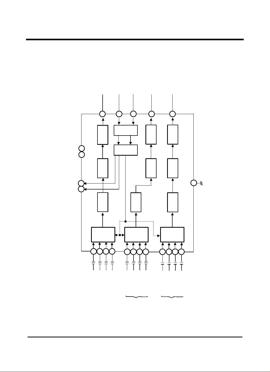
Block Diagram
GL3812
16
MODE-IN
INTERFACE
BUFFER
20
8
DECODER
15 14
7
8
12
19
1
2
3
-
-
-
-
-
E-
11
13
1
1 3 2
1
2
-
-
-
18
22
3
-
-
-
17
10
4
5
6
21
3
1
2
-
-
-
-
Page 3

3
15 20
10 —
—
20 —
15 20
—
Ω
50 —
60 —
—- —
12 14
—
20 —
15 20
—
60 —
70 —
—
— —
—
— —
GL3812
Electrical Characteristics: ,C°25=
Current Dissipation
Video Channel Bandwidth
Video Signal Voltage Gain
Video Signal
Input Dynamic Range
Video Channel PSRR
Video Channel Input Impedance
Video Channel Output Impedance
Video Channel Crosstalk
Video Channel S/N
Audio Channel Bandwidth
Audio Signal Voltage Gain
Audio Signal
Input Dynamic Range
Audio Channel PSRR
Audio Channel Input Impedance
Audio Channel Output Impedance
Audio Channel Crosstalk
Audio Channel S/N
Audio Signal THD
Input Mode Selection
Threshold Voltage
PIN 14 (
Low Level Voltage
PIN 14 (
High Level Voltage
PIN 15 (TV/L)
Low Level Voltage
PIN 15 (TV/L)
High Level Voltage
PARAMETER SYMBOL CONDITIONS MIN TYP MAX UNIT
V /H)
3
V /H)
3
T V12=
A
I V12=V=V
F -3dB Frequency
V
A f=500 kHz,
V
D
V
PS
R
IV
R
OV
CT f=3.58 MHz,
SN
F -3dB frequency
A
A f=1 kHz,
a
D
a
PS
a
R
ia
R
oa
CT f=1 kHz
a
SN
THD f=1 kHz,
V
MTH
V
V
V TV mode selection
V
2,1CC
V
V
V
a
a
TV,L
TV,H
3V,L
3V,H
V
CC
f=500 kHz,
THD < 1 %
V
1CC
Sine Wave (50Hz/60Hz)
V
out
f=1 kHz
THD < 1 %
V
2CC
Sine Wave (50Hz/60Hz)
V
OUT
TV or 1V or 2V
1 mode selection
V mode selection
3
V or 2V or 3V
1
1 mode selection
2CC1CC
V2=
p.p
V2=
p.p
V
OUT
V1+V12=
V1+V12=
V1V =
p.p
V1=INV
V5.0=INV
p.p
p.p
V2=
p.pIN
p.p
p.p
10
5
5.0
1.7
15
10
— 200
40
50
100
10
0.7
15
10
— 200
50
60
— 0.5
2.0
—
10
—
10
6.0
2.0
1.0
2.3
mA
MHz
7.0 dB
V
DB
K Ω
DB
DB
KHz
DB
V
DB
KΩ
Ω
DB
DB
1.5 %
2.6 V
0.5 V
V
0.5 V
V
p.p
p.p
Page 4

4
Pin Description
V
No. Name Explanation No. Name Explanation
1 AUDIO-IN (
2 AUDIO-IN (
3 AUDIO-IN (
4 AUDIO-IN (
5 AUDIO-IN (
6 AUDIO-IN (
7 VIDEO-IN (
8
9 VIDEO-IN (
10 GND 21 AUDIO-IN (R-TV) Input of R-CH Audio
11 MODE-IN (C0) Input for Mode Selection.
L ) Input of L-Ch Audio Signal
1
for Video (
L ) Input of L-Ch Audio Signal
2
for Video (
L ) Input of L-Ch Audio Signal
3
for Video (
R ) Input of R-Ch Audio Signal
1
for Video (
R ) Input of R-Ch Audio Signal
2
for Video (
R ) Input of R-Ch Audio Signal
3
for Video (
V ) Input of V Video Signal. 18 AUDIO-OUT (L) Output of Selected L-CH
1
Power Supply for Video
1CC
V ) Input of video Signal. 20
and Logic Block.
2
V ).
1
V ).
2
V ).
3
V ).
1
V ).
2
V ).
3
13 MODE-IN (C1) Input for Mode
Selection
14 MODE-OUT (
15 MODE-OUT (TV/L) Output Voltage of this Pin
16 VIDEO-OUT Output of Selected Video
17 AUDIO-OUT(R) Output of Selected R-CH
19 VIDEO-IN (TV) Input of TV Video Signal
V Power Supply for Audio
V /H) Output Voltage of this Pin
3
2CC
Becomes High State,
Only when
Else Low State
Becomes Low State, Only
when TV is selected.
Else High State.
Signal
Audio Signal
Audio Signal
Block
Signal for Video (TV).
GL3812
V is Selected
3
12 VIDEO-IN (
V ) Input of V Video Signal.
3
22 AUDIO-IN (L-TV) Input of L-CH Audio
Signal for Video (TV).
Page 5

5
Test Circuit
10µF/50V
10µF/50V
10µF/50V
µF/50V
+
5V 50 50 1K 1K 10K
50
+
µF/50V
1µF/50V
+
+
35K AUDIO SIGNAL IN
LCH 75
75
1µF/50V
µF/50V
+
+
50
µF/50V µF/50V
+
+
75
75
µF/50V µF/50V
+
+
µF/50V
1
2
5
7 8 9
11
12
13
14
15
16
17
18
19
20
21
22
10
GL3812
35K
GL3812
×2
×3
Page 6

6
Application Circuit
1
10 9 8 7 6 5 4
3
22
21
13
14
15
16
17
18
19
20
12 2 1M
35K
1ì F
1M
35K
1ì F
1M
35K
1M
35K
1ì F
1M
35K
1ì F
1M
35K
75
11
75
10ì F
75
75
1M
35K
1ì F
10ì F
1M
35K
1ì F
GL3812
GL3812
* In case of not using Pin 14 or 15, Connect to Ground.
In case of not using Pin 11, Connect to VCC.
In case of not using Pin 13, Connect to Ground.
 Loading...