

Page 1

GENERAL INFORMA TION
A GENERAL INFORMATION
GI
B
SECTION
CONTENTS
PRECAUTIONS .......................................................... 3
Description ............................................................... 3
Precautions for Supplemental Restraint System
(SRS) “AIR BAG” and “SEAT BELT PRE-TEN-
SIONER” .................................................................. 3
Precautions for NVIS/IVIS (NISSAN/INFINITI
VEHICLE IMMOBILIZER SYSTEM - NATS) (If
Equipped) ................. ................................................ 3
General Precautions ................................................ 4
Precautions for Three Way Catalyst ......................... 5
Precaution s for Fuel (Unle aded Premium Gasoline
Recommended) ........ ............. ............. ............. ......... 5
Precautions for Multiport Fuel Injection System or
Engine Control System ............................................ 6
Precautions for Hoses .............................................. 6
HOSE REMOVAL AND INSTALLATION ............... 6
HOSE CLAMPING ................................................ 6
Precautions for Engine Oils ...................................... 7
HEALTH PROTECTION PRECAUTIONS ............. 7
ENVIRONMENTAL PROTECTION PRECAU-
TIONS ................................................................... 7
Precautions for Air Conditioning ............................... 7
HOW TO USE THIS MANUAL ................................... 8
Description ............................................................... 8
Terms ....................................................................... 8
Units ......................................................................... 8
Contents ...................................... ............................. 8
Components ................................ ............................. 9
SYMBOLS ................... .......................................... 9
How to Follow Trouble Diagnoses .......................... 10
DESCRIPTION ................................ .................... 10
HOW TO FOLLOW TEST GROUPS IN TROU-
BLE DIAGNOSES ............................................... 10
HARNESS WIRE COLOR AND CONNECTOR
NUMBER INDICATION ........................................11
KEY TO SYMBOLS SIGNIFYING MEASURE-
MENTS OR PROCEDURES ................. ....... ....... 12
How to Read Wiring Diagrams ............................... 14
CONNECTOR SYMBOLS ................................... 14
SAMPLE/WIRING DIAGRAM - EXAMPL - ......... 15
GENERAL INFORMATION
DESCRIPTION ............................ ........................16
Abbreviations ........ ................................. ................. 22
SERVICE INFORMATION FOR ELECTRICAL INCI-
DENT .............................. ........................................... 23
How to Check Terminal ........................................... 23
CONNECTOR AND TERMINAL PIN KIT ............23
HOW TO PROBE CONNECTORS ......................23
How to Perform Efficient Diagnosis for an Electrical
Incident ........................ ...........................................26
WORK FLOW ......................................................26
INCIDENT SIMULATION TESTS ........................ 26
CIRCUIT INSPECTION ....................................... 29
Control Units and Electrical Parts ...........................34
PRECAUTIONS .................................................. 34
CONSULT-II CHECKING SYSTEM .......................... 36
Description ................... ...... ....... ...... ........................ 36
Function and System Application ........................... 36
Nickel Metal Hydride Battery Replacement ............36
Checking Equipment .............................................. 37
CONSULT-II Start Procedure ................. ...... ....... .... 37
CONSULT-II Data Link Connector (DLC) Circuit .... 38
INSPECTION PROCEDURE ..............................39
LIFTING POINT .........................................................40
Special Service Tools .............................................40
Garage Jack and Safety Stand ...............................40
2-pole Lift ................................................................41
Board-on Lift ........................................................... 42
TOW TRUCK TOWING .............................................43
Tow Truck Towing ................................................... 43
Vehicle Recovery (Freeing a Stuck Vehicle) ........... 43
FRONT ................................................................ 43
REAR ..................................................................43
TIGHTENING TORQUE OF STANDARD BOLTS ....44
Tightening Torque Table ......................................... 44
RECOMMENDED CHEMICAL PRODUCTS AND
SEALANTS ............................................................... 45
Recommended Chemical Products and Sealants ...45
IDENTIFICATION INFORMATION ........................ .... 46
Model Variation .......................................................46
IDENTIFICATION NUMBER ................................ 47
C
D
E
F
G
H
I
J
K
L
M
GI-1
Page 2

IDENTIFICATION PLATE .................................... 47
ENGINE SERIAL NUMBER ..... ....... ...... ....... ....... 48
AUTOMA TIC TRANSMISSION NUMBER ...........48
MANUAL TRANSMISSION NUMBER .................48
Dimensions .............................................................49
Wheels & Tires ........................................................49
TERMINOLOGY ........................................................50
SAE J1930 Terminology List ...................................50
GI-2
Page 3

PRECAUTIONS
PRECAUTIONS PFP:00001
Description AAS00009
Observe the following precautions to ensure safe and proper servicing. Thes e precautions are not
described in each individual section.
Precautions for Supplemental Restraint System (SRS) “AIR BAG” and “SEAT BELT PRE-TENSIONER”
The Supplemental Rest raint System such as “AIR BAG” and “SEAT BELT PRE-TENSIONER”, used along
with a front seat belt, helps to redu ce th e risk or se verit y of i njury to the driv er and front passenge r for ce rtain
types of collision. This system includes seat belt switch inputs and dual stage front air bag modules. The SRS
system uses the seat belt switches to determine the front air bag deployment, and may only deploy one front
air bag, depending on the severity of a collision and whether the front occupants are belted or unbelted.
Information necessary to service the system safely is included in the SRS and SB section of this Service Manual.
WARNING:
● To avoid rendering the SRS inopera tive, which c ould increa se the risk of perso nal injury or dea th
in the event of a collision which would result in air bag inflation, all maintenance must be performed by an authorized NISSAN/INFINITI dealer.
● Improper maintenance, inc luding incorrect removal and installation of the SRS, can lead to per-
sonal injury ca use d by unintentional ac tiv atio n o f the system. For remo va l of Spiral Cable and Air
Bag Module, see the SRS section.
● Do not use electrical test equ ipment o n any circu it related to the SRS unless in structed to in this
Service Manual. SRS wiring harnesses can be identified by yellow and/or orange harnesses or
harness connectors.
AAS0001B
GI
B
C
D
E
F
G
H
Precautions for NVIS/IVIS (NISSAN/INFINITI VEHICLE IMMOBILIZER SYSTEM NATS) (If Equipped)
NVIS/IVIS (N ATS) will immob il iz e the e ng i ne if s ome one tr i es to s tart it wit h ou t th e r e gist e re d ke y o f NV I S/ IVI S
(NATS).
Both of the originally supplied ignition key IDs have been NVIS/IVIS (NATS) registered.
The security indic ator i s lo cated on the in strum ent panel. T he in di cato r blin ks wh en th e im mobi lizer sys tem i s
functioning.
Therefore, NVIS/IVIS (NATS) warns outsiders that the vehicle is equipped with the anti-theft system.
● When NVIS/IVIS (NATS) detects trouble, the security i ndicator lamp lights up while ignition switch is in
"ON" position.
This lighting up indicates that the anti-theft is not functioning, so prompt service is required.
● When servicin g NVIS/IVIS (NATS) (trouble diag noses, syst em initializatio n and addition al registration of
other NVIS/IVIS (NATS) ignition key IDs), CONSULT-II hardware and CONSULT-II NVIS/IVIS (NATS)
software is necessary.
Regarding the procedures of NVI S/IVIS (NATS) initialization and NVIS/I VIS (NATS) ignition key ID re gistration, refer to CONSULT-II operation manual, NVIS/IVIS (NATS).
Therefore, CONSULT-II NVIS/IVIS (NAT S) software (pro gram ca rd and operatio n manual) m ust be kept
strictly confidential to maintain the integrity of the anti-theft function.
● When servicin g NVIS/IVIS (NATS) (trouble diag noses, syst em initializatio n and addition al registration of
other NVIS/IVIS (NATS) ignition key IDs), it may be necessary to re-register original key identification.
Therefore, be sure to receive all keys from vehicle owner. A maximum of four or five key IDs can be registered into NVIS/IVIS (NATS).
● When failing to start the engine first time using the key of NVIS/IVIS (NATS), start as follows.
1. Leave the ignition key in "ON" position for approximately 5 seconds.
2. Turn ignition key to "OFF" or "LOCK" position and wai t approximately 5 seconds.
3. Repeat step 1 and 2 again.
4. Restart the engine while keeping the key separate from any others on key-chain.
AAS0000B
I
J
K
L
M
GI-3
Page 4
PRECAUTIONS
General Precautions
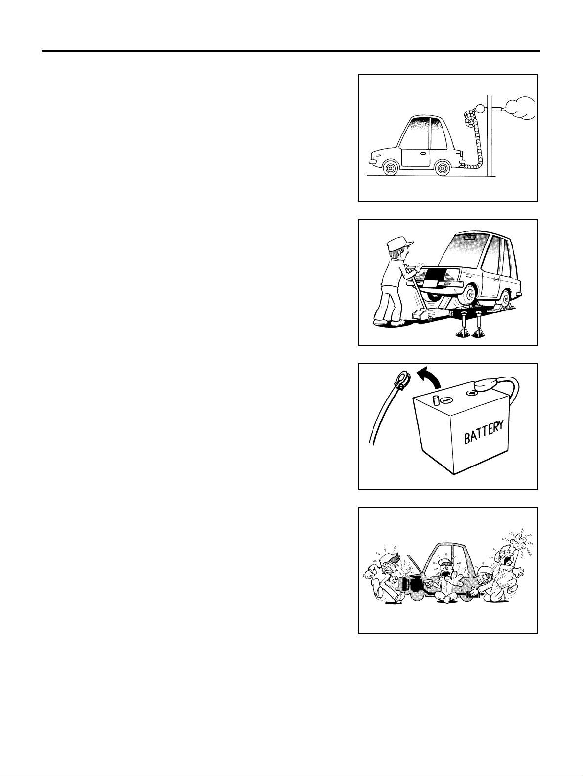
● Do not ope rate t he en gine f or an exte nded perio d of t ime wi thou t
proper exhaust ventilat ion.
Keep the work area well ventilated and free of any inflammable
materials. Special care should be taken when handling any
inflammable or pois onous materials, suc h as gasoline, refrig erant gas, etc. When working in a pit or other enclosed area, be
sure to properly ventila te the area before working with haza rdous materials.
Do not smoke while working on the vehicle.
● Before jacking up the vehicle, apply wheel chocks or other tire
blocks to the wheel s to prevent the vehicle from movin g. After
jacking up the vehicle, support the vehicle weight with safety
stands at the points designat ed for proper lifting be fore working
on the vehicle.
These operations should be done on a level surface.
● When removing a heavy component such as the en gin e or tra n-
saxle/transmiss io n, be care fu l not to los e yo ur ba la nc e an d dro p
them. Also, do not allow them to strike adjacent parts, especially
the brake tubes and master cylinder .
AAS0000C
SGI285
SGI231
● Before starting repairs which do not require battery power:
Turn off ignition switch.
Disconnect the negative battery terminal.
● If the battery termin als are disconnected, recorded memory of
radio and eac h control unit is erased.
SEF289H
● To prevent serious burns:
Avoid contact with hot metal parts.
Do not remove the radiator cap when the engine is hot.
● Dispose of drained oil or the solvent us ed for cleaning parts in
an appropriate manner.
● Do not attempt to top off the fuel tank aft er th e f ue l pu m p n ozzl e
shuts off automatically.
Continued refueling may cause fuel overflow, resulting in fuel
spray and poss ibly a fire.
● Clean all disassembled parts in the designated liquid or solvent
prior to inspection or assembly.
● Replace oil seals, gaskets, packings, O-rings, locking washers, cotter pins, self-locking nuts, etc. with new
SGI233
ones.
● Replace inner and outer races of taper ed roller bearings and needle bearings as a set.
● Arrange the disassembled parts in accordance with their assembled locations and sequence.
● Do not touch the terminals of electrical component s which use microcomputers (s uch as ECM).
Static electricity may damage internal electronic components.
● After disconnecting vacuum or air hoses , attach a tag to indicate the proper connection.
● Use only the fluids and lubricants specified in this manual.
GI-4
Page 5
PRECAUTIONS
● Use approved bonding agent, sealants or t heir equivalents when required.
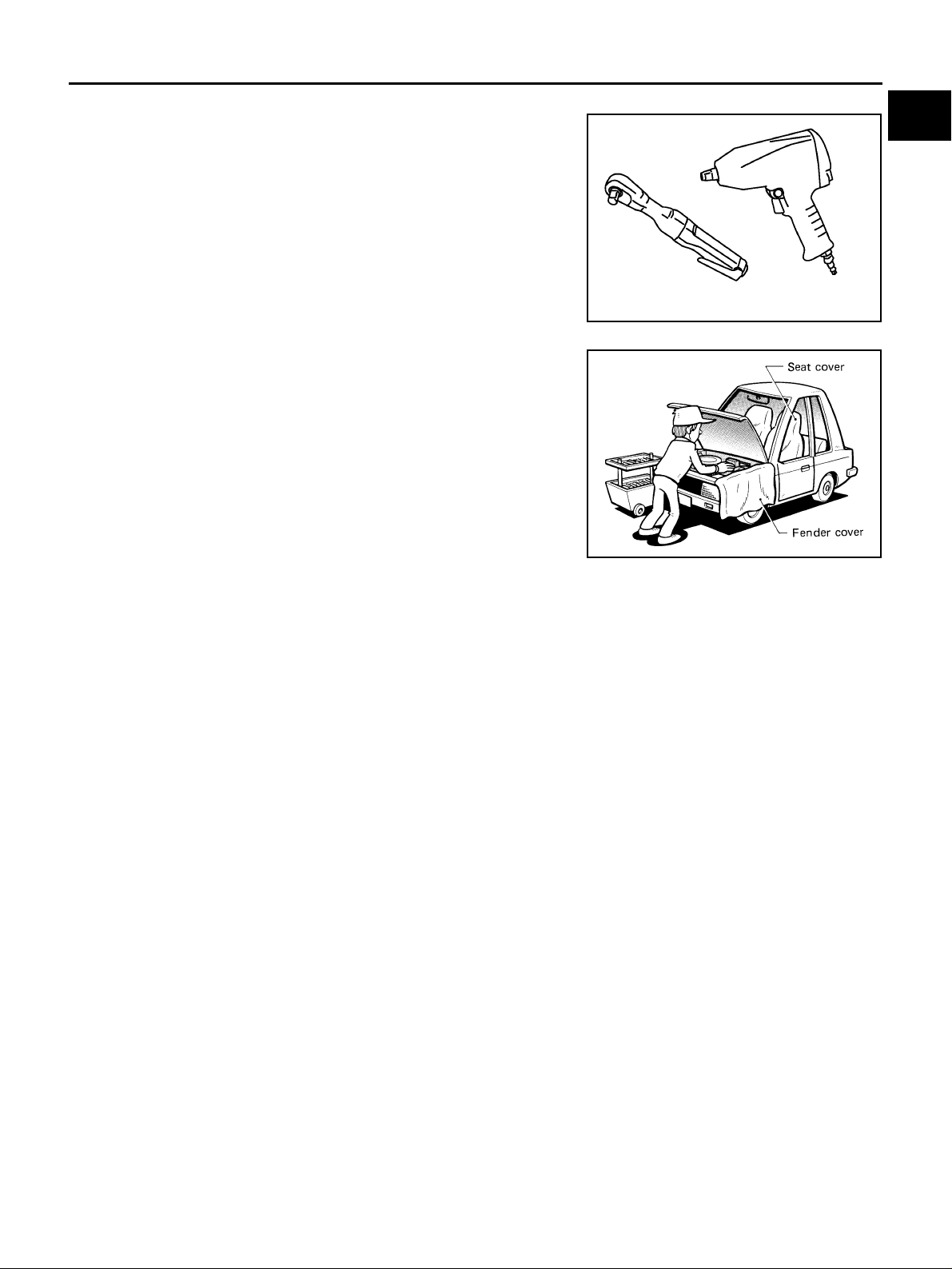
● Use hand tools, power tools (disassembly only) and recom-
mended special tools where specified for safe and efficient service repairs.
● When repairing the fu el, oil, wate r, vacuum or exhaust sys tems,
check all affected lines for leaks.
GI
B
C
PBIC0190E
● Before servici ng the vehicle:
Protect fenders, u pholstery and carp eting with appropriat e covers.
Take caution that keys, bu ckles or button s do not scratch paint.
SGI234
WARNING:
To prevent ECM from storing the diagnostic trouble codes, do not careless ly disconnect the harness
connectors which are related to the engine control system and TCM (transmission control module)
system. The connectors should be disconnected only when working according to the WORK FLOW of
TROUBLE DIAGNOSES in EC and AT sections.
Precautions for Three Way Catalyst AAS0000D
If a large amount of unburned fuel flows into the catalyst, the catalyst temperature will be excessively high. To
prevent this, follow the ins tru cti on s.
● Use unleaded gasoline only. Leaded gasoline will seriously damage the three way c atalyst.
● When checki ng for ignition spark or m easuring engine com pression, make tests q uickly and only whe n
necessary.
● Do not run engine when the fuel tank level is low, otherwise the engine may misfire, causing damage to
the catalyst.
Do not place the vehicle on flammable ma terial. Keep flamm able material off the exha ust pipe and the thre e
way catalyst.
D
E
F
G
H
I
J
K
L
M
Precautions for Fuel (Unl eaded Premium Gasoline Recommended) AAS000A4
Use unleaded regular gasoline with an octane rating of at least 87 AKI (Anti-Knock Index) number (Research
octane number 91).
For improved vehi cl e per form ance, NISSAN/INFIN ITI rec o mm en d th e us e of un leaded premium gaso line with
an octane rating of at lea s t 91 AKI number (Research octane number 96).
CAUTION:
Do not use leaded gasoline. Using leaded gasoline will damage the three way catalyst. Using a fuel
other than that specified cou ld adversel y affect the emis sion control de vices and systems, and could
also affect the warranty coverage validity.
GI-5
Page 6
PRECAUTIONS
Precautions for Multiport Fuel Injection System or Engine Control System
● Before connecting or disconnecting any harness co nnector for
AAS0000F
the multiport fuel injection system or ECM:
Turn ignition switch to “OFF” position.
Disconnect negative battery terminal.
Otherwise, there may be damage to ECM.
● Before disconnecting pressurized fuel line from fuel pump to
injectors, be sure to release fuel pressure.
● Be careful not to jar components such as ECM and mass air
flow sensor.
SGI787
Precautions for Hoses AAS0000H
HOSE REMOVAL AND INSTALLATION
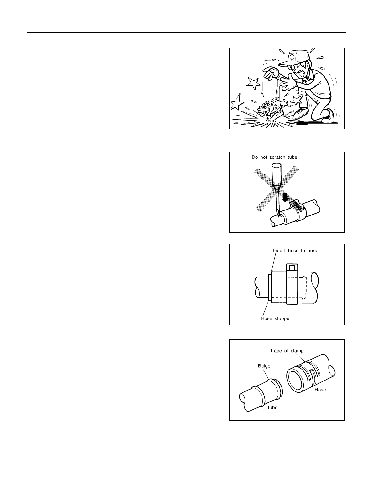
● To prevent damage to rubber hose, do not pry off rubber hose
with tapered tool or screwdriver.
● To reinstall the rubber hose securely, make sure that hose inser-
tion length and orientation is correct. (If tube is equipped with
hose stopper, insert rubber hose into tube until it butts up
against hose stopper.)
HOSE CLAMPING
● If old rubber hose is re-used, install hose clamp in its original
position (at the ind entation whe re the ol d clamp wa s). If ther e is
a trace of tube bulging left on the old rubber hose, align rubber
hose at that position.
● Discard old clamps; replace with ne w ones.
SMA019D
SMA020D
GI-6
SMA021D
Page 7
PRECAUTIONS
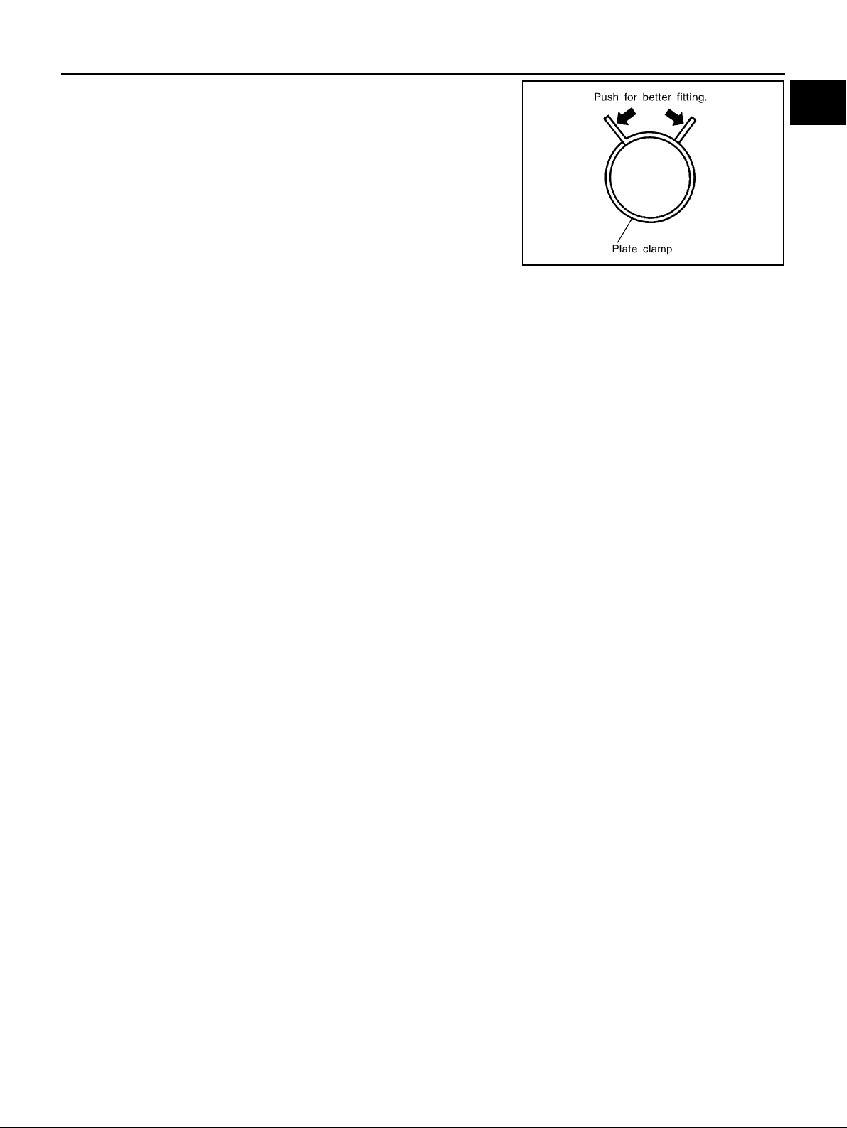
● After installing pl ate cla mps, apply fo rce to th em in th e directi on
of the arrow, tightening rubber hose equally all around.
SMA022D
Precautions for Engine Oils AAS0000I
Prolonged and repeated contact with used engine oil may cause skin cancer. Try to avoid direct skin contact
with used oil.
If skin contact is made, wash thoroughly with soap or hand cleaner as soon as possible.
HEALTH PROTECTION PRECAUTIONS
● Avoid prolonged and repeated contact with oils, particularly used engine oils.
● Wear protective clothing, including impervious gloves where practicable.
● Do not put oily rags in pockets.
● Avoid contaminating clothes, particularly underpants, with oil.
● Heavily soil ed c l o thi ng a nd oil-impregnate d foo tw e ar s h ou ld not be worn. Ove r al ls m us t b e cleaned regu-
larly.
● First aid treatment should be obtained immediately for open cuts and wounds.
● Use barrier creams, applying them before each work period, to help the removal of oil from the skin.
● Wash with soap and water to ensu re all oil is removed (ski n clea nse rs a nd nail b rus hes will he lp) . Prepa-
rations containing lanolin repla c e the natural skin oils which have been removed.
● Do not use gasoline, kerosene, diesel fuel, gas oil, thinners or solvents for cleani ng skin.
● If skin disorders develop, obtain medical advice without delay.
● Where practical, degrease components prior to handling.
● Where there is a risk of eye contact, eye protection should be worn, for example, chemical goggles or face
shields; in addition an eye wash facility should be provided.
ENVIRONMENTAL PROTECTION PRECAUTIONS
Dispose of used oil and used oil filters through authorized waste disposal contractors to licensed waste disposal sites, or to the waste oil reclamation trade. If in doubt, contact the local authority for advice on disposal
facilities.
It is illegal to pour used oil on to the grou nd, down sewer s or drains, or into water sources.
The regulations co nc ern in g pol lu tio n va ry between regions.
Precautions for Air Conditioning AAS0000J
GI
B
C
D
E
F
G
H
I
J
K
L
M
Use an approved refrig erant recov ery unit any time the air condi tioning syst em must be disc harged. Refe r to
ATC/MTC section “HFC-134 a (R-134a) Service Procedure”, “REFRIGERANT LINES” for specific instructions.
GI-7
Page 8

HOW TO USE THIS MANUAL
HOW TO USE THIS MANUAL
PFP:00008
Description AAS0000K
This volume expla ins “Removal, Disassembly, Installation, Inspection and Adjustment” and “Trouble Diagnoses”.
Terms AAS0000L
● The captions WARNING and CAUTION warn you of steps that must be followed to prevent personal
injury and/ or damage to some part of the vehicle.
WARNING indicates the possibility of personal injury if instructions are not followed.
CAUTION indicates the possibility of component damage if instructions are not followed.
BOLD TYPED STATEMENTS except WARNING and CAUTION give you helpful information.
Standard value:Tolera nc e at insp ec tio n an d adj us tment.
Limit value:The maximum or minimu m limit value that sh ould not be exceed ed at inspection an d adjustment.
Units AAS000KL
● The UNITS given in this manual are primarily expressed as the SI UNIT (International System of Unit),
and alternatively expressed in the metric system and in the yard/pound system.
Also with regard to tightening torque of bolts and nuts, there are descriptions both about range and about
the standard tightening torque.
“Example”
Range
Outer Socket Lock Nut : 59 - 78 N-m (6.0 - 8.0 kg-m, 43 - 58 ft-lb)
Standard
Drive Shaft Installation Bolt : 44.3 N-m (4.5 kg-m, 33 ft-lb)
Contents AAS0000N
● ALPHABETICAL INDEX is provided at the end of this manual so that you can rapidly find the item and
page you are searching for.
● A QUICK REFERENCE INDEX, a black tab (e.g. ) is provided on th e firs t page. You can quickly find
the first page of each section by matching it to the section's black tab.
● THE CONTENTS are listed on the first page of each section.
● THE TITLE is indicated on the upper portion of each page and shows the part or system.
● THE PAGE NUMBER of eac h secti on con sists of tw o or thre e let ters whic h desi gnate t he particu lar sec -
tion and a number (e.g. “BR- 5”).
● THE SMA LL ILLUSTRATIONS show the important steps such as inspection, use of special tools, knacks
of work and hidden or tricky steps which are not shown in the previous large illustrations.
Assembly, inspection and adjus tment procedures for the complicated units such a s the automatic transaxle or transmission, etc. are presented in a step-by-step format where necessary.
GI-8
Page 9
HOW TO USE THIS MANUAL
Components AAS000KM
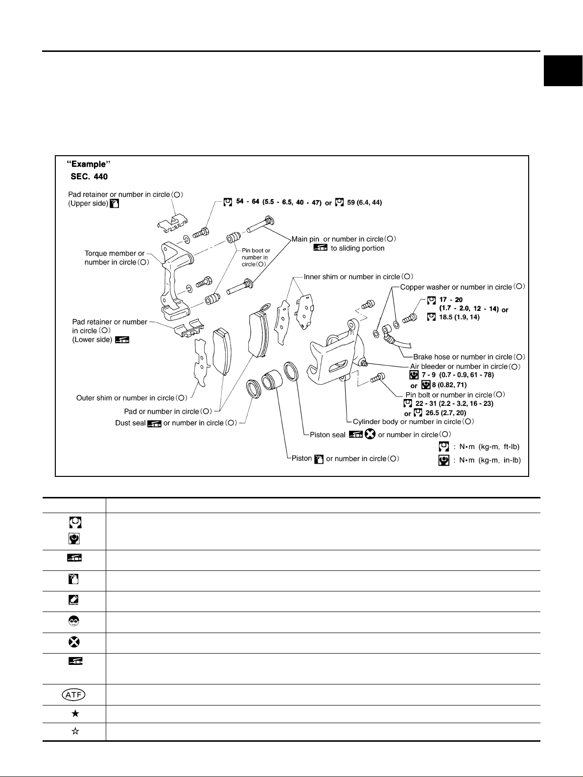
● THE LARGE ILLUSTRATIONS are exploded views (See the followin g) and contain tightening torques,
lubrication points, section number of the P ARTS CATALOG (e.g . SEC . 440) an d oth er info rma tio n neces -
sary to perform repairs.
The illustrations should be used in reference to service matters only. When ordering parts, refer to the
appropriate PARTS CATALOG .
Components shown in an illustration may be identified by a circled number. When this style of illustration
is used, the text description of the components will follow the illustration.
GI
B
C
D
E
F
G
SYMBOLS
SYMBOL DESCRIPTION
Tightening torque
The tightening torque specifications of bolts and nuts may be presented as either a range or a standard tightening
torque.
Should be lubricated with grease. Unless otherwi se indicated, use recommended multi-purp ose grease.
Should be lubricated with oil.
Sealing point
Checking point
H
I
J
K
SAIA0399E
L
M
Always replace after every disassembly.
P
Apply petroleum jelly.
Apply ATF.
Select with proper thickness.
Adjustment is required.
GI-9
Page 10
HOW TO USE THIS MANUAL
How to Follow Trouble Diagnoses
AAS0000P
DESCRIPTION
NOTICE:
Trouble diagnoses indi cate work proce dures req uired to diag nose proble ms effec tivel y. Observe the following
instructions before diagnosing.
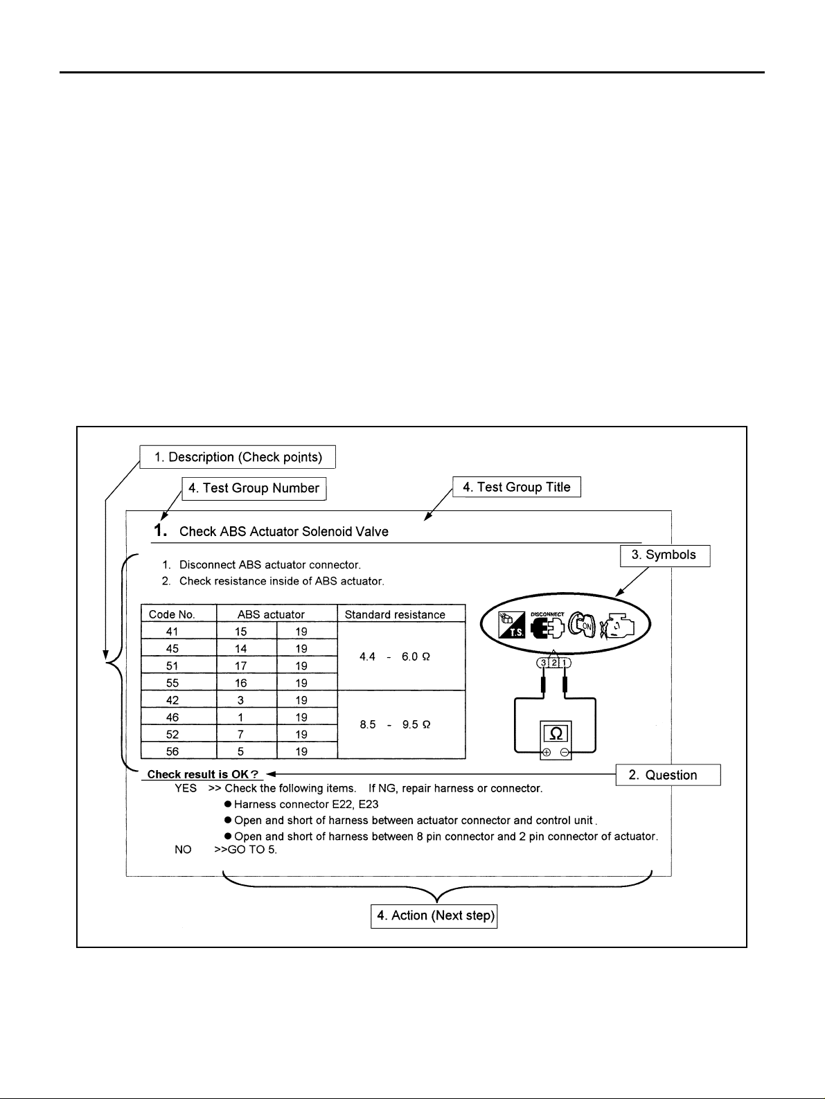
1. Before performing trouble diagnoses, read the “ Preliminary Check”, the “Sy mptom Chart” or the
“Work Flow”.
2. After repairs, re-check that the problem has been complete ly eli min ate d.
3. Refer to Component Parts and Harn ess Connector Location for the Systems de scribed in each
section for identification/location of components and harness connectors.
4. Refer to the Circuit Diagram for quick pinpoint check.
If you need to check circuit continuity between harness connectors in more detail, such as when a
sub-harness is used, refer to Wiring Diagram in each individual section and Harness Layout in PG
section for identification of harness connectors.
5. When checking circuit continuity, ignition switch should be OFF.
6. Before checking voltage at connectors, check battery voltage.
7. After accomplishing the Diagnostic Procedures and Electrical Components Inspection, make sure
that all harness connectors are reconnected as they were.
HOW TO FOLLOW TEST GROUPS IN TROUBLE DIAGNOSES
1. Work a nd diagnostic procedure
Start to diagnose a problem using procedures indicated in enclosed test groups.
2. Questions and required results
Questions and required results are indicated in bold type in test group.
The meaning of are as follows:
GI-10
SAIA0256E
Page 11
HOW TO USE THIS MANUAL
a. Battery voltage → 1 1 - 14V or approximately 12V
b. Voltage : Approxima tely 0V → Less than 1V
3. Symbol used in illustration
Symbols included in illustrations refer to measurements or procedures. Before diagnosing a problem,
familiarize y ourself with ea ch symbol. R efer to "Connec tor Symbols" in GI Section a nd "KEY TO SYMBOLS SIGNIFYING MEASUREMENTS OR PROCEDURES" below.
4. Action items
Next action for ea ch te st gr o up is ind ic at e d base d on r es ult o f e ach qu es ti o n. Test group numb er is sh ow n
in the left upper portion of each test group.
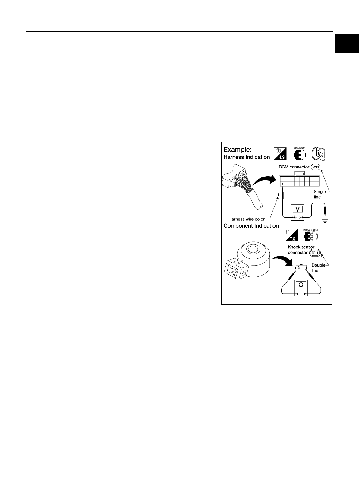
HARNESS WIRE COLOR AND CONNECTOR NUMBER INDICATION
There are two types of harness wire color and connector number indication.
TYPE 1: Harness Wire Color and Connector Number are Shown in Illustration
● Letter designations next to test meter probe indicate harness
wire color.
● Connector numbers in a single circle (e.g. M33) indicate har-
ness connectors.
● Connector numbers in a double circle (e.g. F211) indicate com-
ponent connectors.
GI
B
C
D
E
F
G
H
AGI070
I
J
K
L
M
GI-11
Page 12
HOW TO USE THIS MANUAL
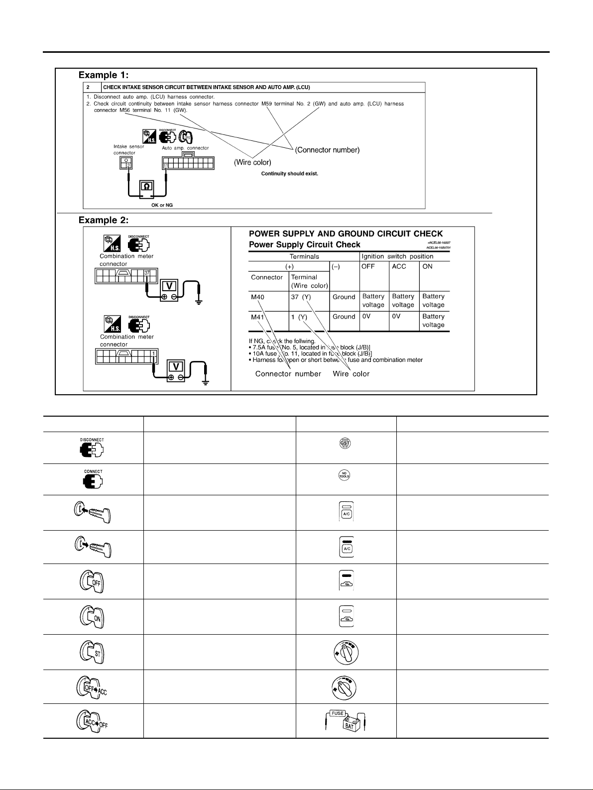
TYPE 2: Harness Wire Color and Connector Number are Shown in Text
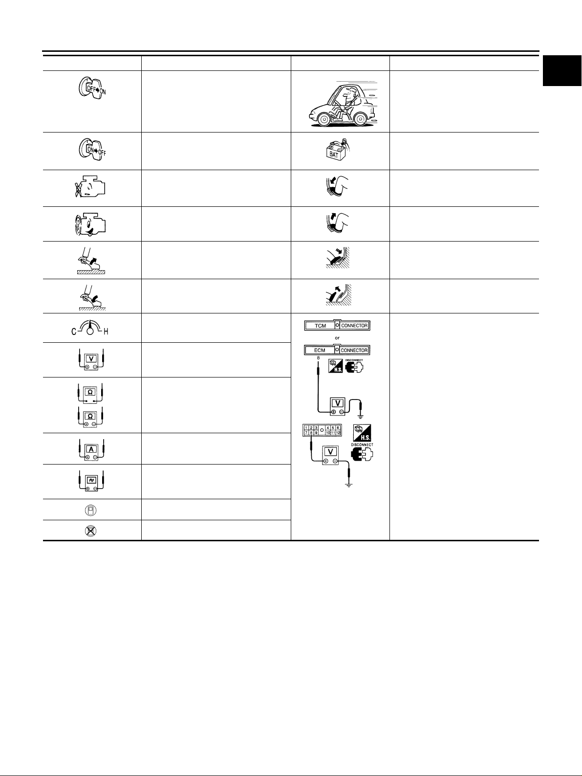
KEY TO SYMBOLS SIGNIFYING MEASUREMENTS OR PROCEDURES
Symbol Symbol explanation Symbol Symbol explanation
Check after disconnecting the con nector to be measured.
Check after connecting the conn ector
to be measured.
Insert key into ignition switch. A/C switch is “OFF”.
Remove key from ignition switch. A/C switch is “ON”.
Turn ignition switch to “OFF” position. REC switch is “ON”.
Turn ignition switch to “ON” position. REC switch is “OFF”.
Turn ignitio n swit ch to “START” position.
Turn ignition switch from “OFF” to
“ACC” position.
Procedure with Generic Scan Tool
(GST, OBD-II scan tool)
Procedure without CONSULT, CONSULT-II or GST
Fan switch is “ON”. (At any position
except for “OFF” position)
Fan switch is “OFF”.
SGI144A
Turn ignition switch from “ACC” to
“OFF” position.
Apply positive voltage from battery
with fuse directly to components.
GI-12
Page 13
HOW TO USE THIS MANUAL
Symbol Symbol explanation Symbol Sy mb ol ex planat i on
Turn ignition switch from “OFF” to
“ON” position.
Turn ignition switch from “ON” to
“OFF” position.
Do not start engine, or check with
engine stopped.
Start engine, or check with engine running.
Apply parking brake. Depress accelerator pedal.
Release parking brake. Release accelerator pedal.
Check after engine is warmed up sufficiently.
Voltage should be measured with a
voltmeter.
Circuit resistance should be measured
with an ohmmeter.
Drive vehicle.
Disconnect battery negative cable.
Depress brake pedal.
Release brake pedal.
Pin terminal check for SMJ type ECM
and TCM connectors.
For details regarding the terminal
arrangement, refer to the “ELECTRICAL UNITS” electrical reference
page at the end of the manual.
GI
B
C
D
E
F
G
H
I
Current should be measured with an
ammeter.
Pulse signal should be checked with
an oscilloscope.
Procedure with CONSULT-II
Procedure without CONSULT-II
J
K
L
M
GI-13
Page 14
HOW TO USE THIS MANUAL
How to Read Wiring Diagrams
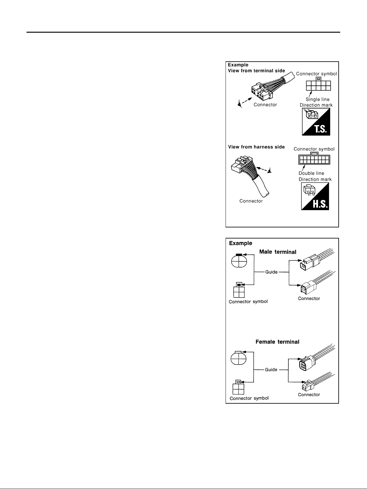
CONNECTOR SYMBOLS
Most of connector symbols in wiring diagrams are shown from the terminal side.
● Connector symbols shown from the terminal side are enclosed
by a single line and followed by the direction mark.
● Connector symbols shown from the harness side are enclosed
by a double line and followed by the direction mark.
● Certain systems and components, especially those related to
OBD, may use a new style slide-locking type harness connector.
For description and how to disconnect, refer to PG section,
“Description”, “HARNESS CONNECTOR”.
AAS0000Q
● Male and female terminals
Connector guides for male terminals are shown in black and
female terminals in white in wiring diagrams.
SAIA0257E
SGI363
GI-14
Page 15
HOW TO USE THIS MANUAL
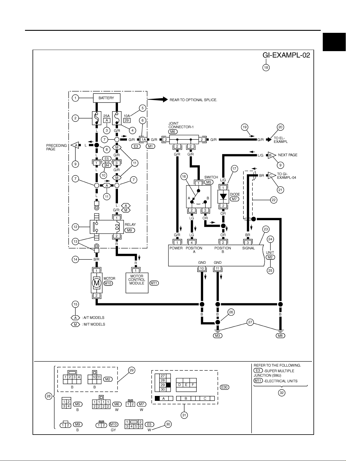
SAMPLE/WIRING DIAGRAM - EXAMPL -
● For detail, refer to following “DESCRIPTION”.
GI
B
C
D
E
F
G
H
K
M
I
J
L
GI-15
SGI091A
Page 16
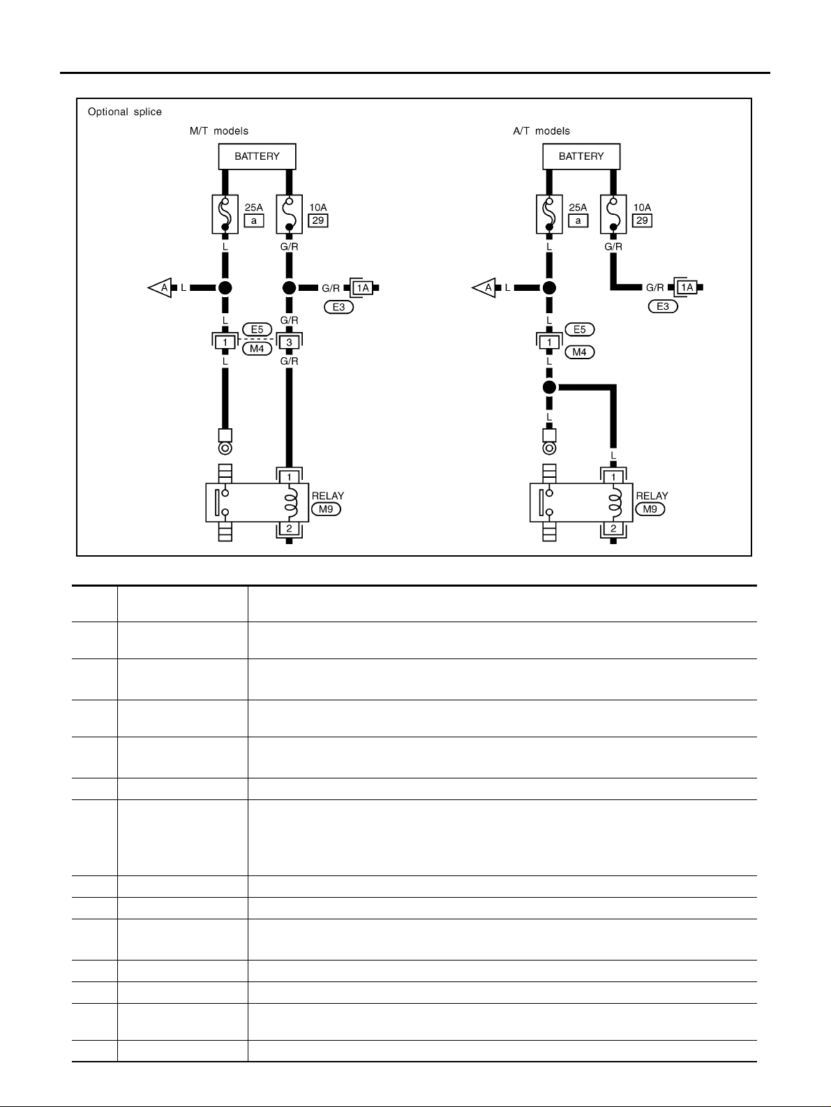
Optional Splice
HOW TO USE THIS MANUAL
DESCRIPTION
Num-
ber
1 Power condition
2 Fusible link
Fusible link/fuse loca-
3
tion
4Fuse
5 Current ra ting
6 Connectors
7 Optional splice
8 Splice
9 Page crossing
10 Common connector
11 Option abbreviation
12 Relay
13 Connectors
SGI942
Item Description
● This shows the condition when the system receives battery positive voltage (can be oper-
ated).
● The double line shows that this is a fusible link.
● The open circ le sh ow s cur ren t flow i n, an d the shaded circle shows current flow out.
● This sho w s the loca tion of the fusibl e l ink or fu se in the fusibl e link or fus e box. For ar ran ge-
ment, refer to PG section, POWER SUPPLY ROUTING.
● The single line shows that this is a fuse.
● The open circ le sh ow s cur ren t flow i n, an d the shaded circle shows current flow out.
● This sho w s the current rat ing of the fu si bl e link or fuse .
● This sho w s tha t connect or E3 is fem ale and connector M1 is male.
● The G/R wire is located in the 1A terminal of both connectors.
● Terminal number with an alphabet (1A, 5B, etc.) indicates that the connector is SMJ connec-
tor. Refer to PG section, SMJ (SUPER MULTIPLE JUNCTION).
● The open circ le sh ow s th at the spli ce is option al de pending on vehicle application.
● The shaded circle shows that the splice is always on the vehicle.
● This arrow sh ow s tha t the ci rcu it cont inues to an adjacent page.
● The A will match with the A on the pre cedi ng or next page.
● The dotted lines between terminals show that these terminals are part of the same connector.
● This sho w s tha t the ci rcu it is optional depending on vehicle application.
● This sho w s an internal rep res entation of the relay. For details, refer to PG section, STAN-
DARDIZED RELAY.
● This sho w s tha t the connector is connected to the body or a terminal with bolt or nut .
GI-16
Page 17
HOW TO USE THIS MANUAL
Num-
ber
Item Description
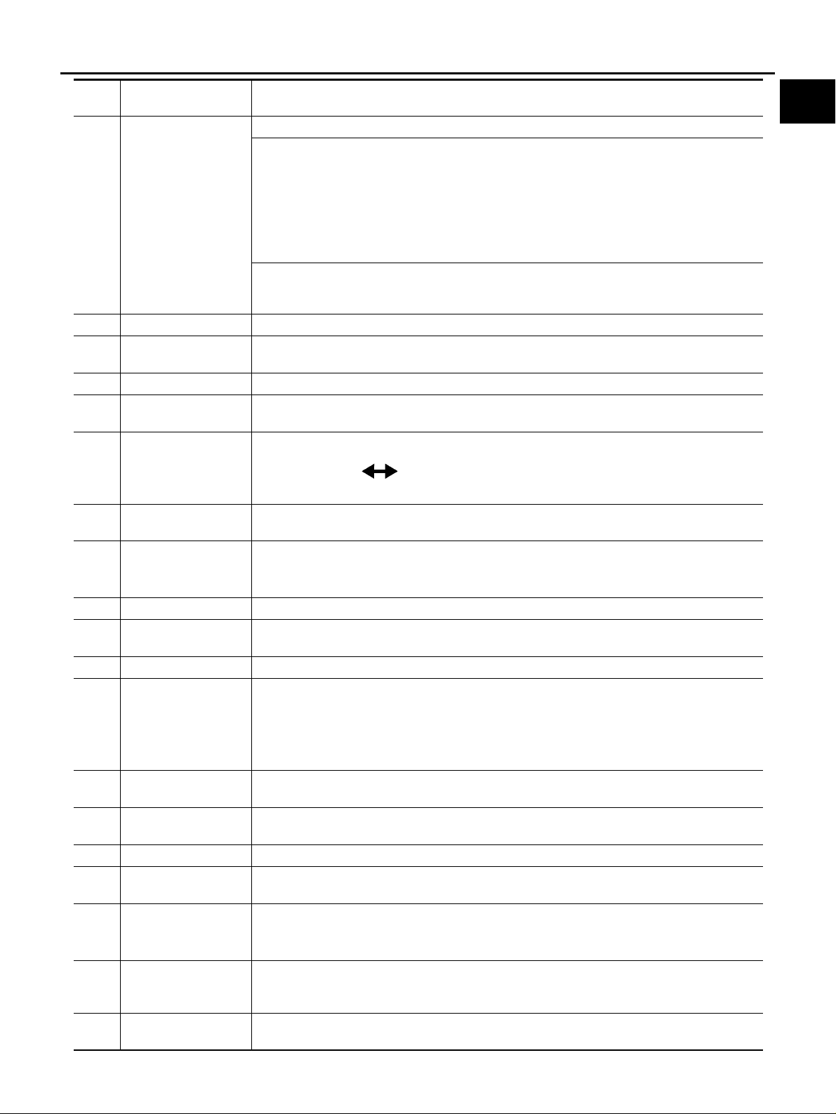
14 Wire color
15 Option description
16 Switch
17 Assembly parts
18 Cell code
19 Current flow arrow
20 System branch
21 Page crossing
22 Shielded line
Component box in
23
wave line
24 Component name
25 Connector number
26 Ground (GND)
27 Ground (GND)
28 Connector views
29 Common component
30 Connector color
● This shows a code for the color of the wire.
B = Black
W = White
R = Red
G = Green
L = Blue
Y = Yellow
LG = Light Green
BR = Brown
OR or O = Orange
P = Pink
PU or V (Violet) = Purple
GY or GR = Gray
SB = Sky Blue
CH = Dark Brown
DG = Dark Green
When the wire color is striped, the base color is given first, followed by the stripe color as shown
below:
Example: L/W = Blue with White Stripe
● This shows a description of the option abbreviation used on the page.
● This shows that continuity exists between terminals 1 and 2 when the switch is in the A posi-
tion. Continuity exists between terminals 1 and 3 when the switch is in the B positio n.
● Conne cto r te rmi nal in component shows that it is a harness incorporated assembly.
● This ident ifies each page of the wiring diagram by section, system and wiring diagram page
number.
● Arrow indicates electric current flow, especially where the direction of standard flow (vertically
downward or horizontally from left to right) is difficult to follow.
● A double ar row “ ” shows that current can flow in either direction depe ndi ng on cir-
cuit operation.
● This shows that the system branches to another system ident i fied by cell code (section and
system).
● This arrow show s that the circuit continues to another page identified by cell code .
● The C will match with the C on another page within the system other than the next or preced-
ing pages.
● The line enclosed by broken line circle shows shield wire.
● This shows that another part of the component is also shown on another page (indicat ed by
wave line) within the system.
● This shows the name of a component.
● This shows the connector number.
● The letter shows w hi ch ha rness the connector is located in.
● Example: M : main harness. For detail and to locate the connector, refer to PG section "Main
Harness", “Harness Layout”. A coordina te grid is included for complex harnesses to aid in
locating connectors.
● The line spl ice d and gr ounded under wire color shows that ground line is spliced at the
grounded connector.
● This shows the ground connection. For detailed ground distribution information, refer to
"Ground Distribution" in PG section.
● This are a shows t he connector faces of the components in the wiring diagram on the page.
● Conne cto rs encl osed in broken line show that these connectors belong to the same compo-
nent.
● This shows a code for the color of the connector. For code meaning, refer to wire color codes,
Number 14 of this chart.
GI
B
C
D
E
F
G
H
I
J
K
L
M
Fusible link and fuse
31
box
32 Reference area
● This shows the arrangement of fusible link(s) and fuse(s) , use d for connector views of
"POWER SUPPLY ROUTING" in PG section.
The open square shows current flow in, and the shaded square shows current flow out.
● This shows that more information on the Super Multiple Junction (SMJ) and Joint Connectors
(J/C) exists on the PG section. Refer to "Reference Area" for details.
GI-17
Page 18
HOW TO USE THIS MANUAL
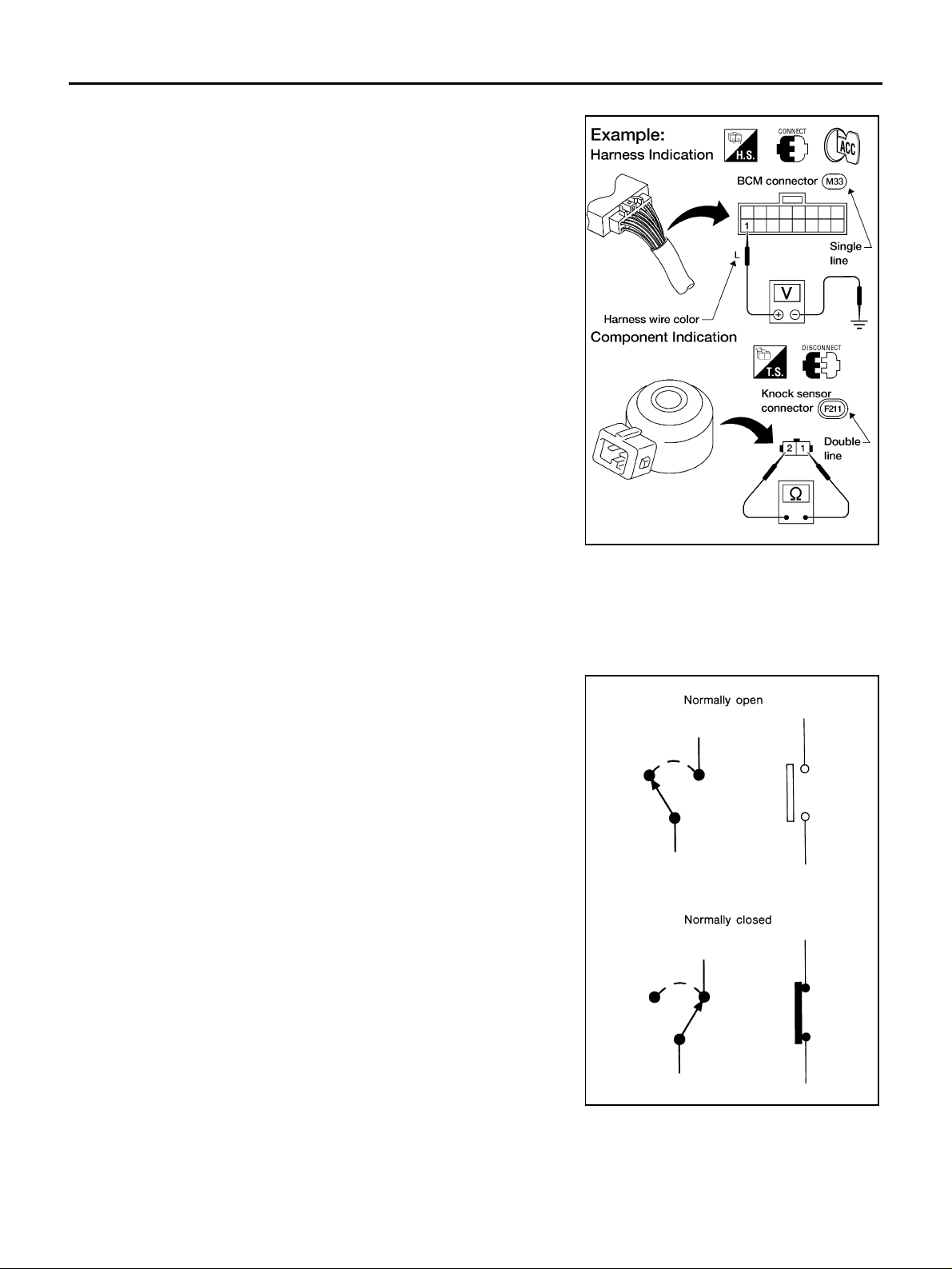
Harness Indication
● Letter designations next to test meter probe indicate harness
(connector) wire color.
● Connector numbers in a sing le circ le M3 3 indic ate ha rness co n-
nectors.
Component Indication
Connector numbers in a double circle F211 indicate component connectors.
Switch Positions
Switches are shown in wiring diagrams as if th e vehicle is in the “normal” condition.
A vehicle is in the “normal” condition when:
● ignition switch is “OFF”,
● doors, hood and trunk lid/b ac k door are closed,
● pedals are not depressed, and
● parking brake is released.
AGI070
GI-18
SGI860
Page 19
HOW TO USE THIS MANUAL
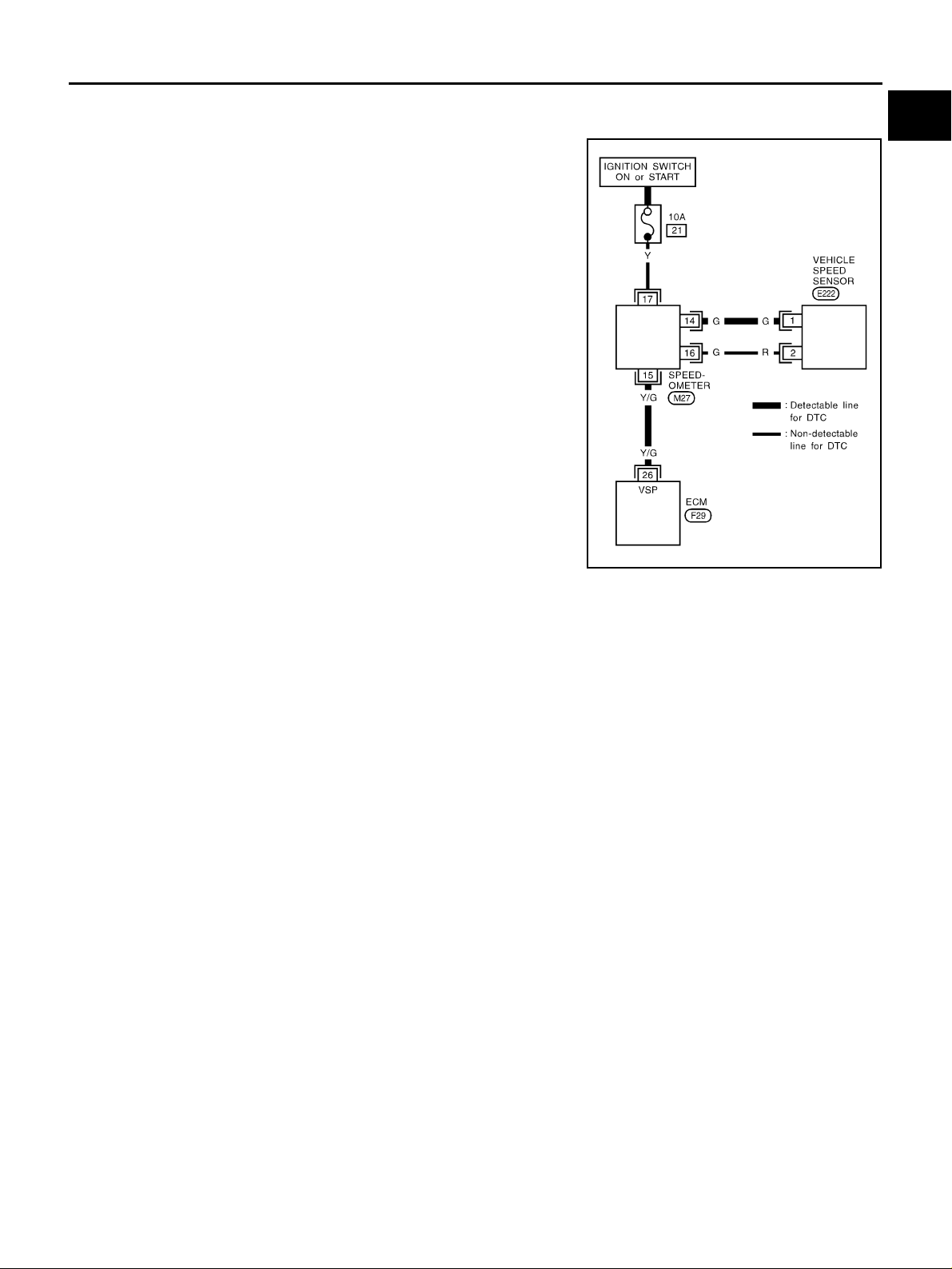
Detectable Lines and Non-Detectable Lines
In some wiring diagrams, two kind s of lin es , rep res en tin g w ire s, with different weight are used.
● A line with regula r weight (wider line) represents a “detectable
line for DTC (Diagnostic Trouble Code)”. A “detectable line for
DTC” is a circu it in which ECM can detect its malf unctions with
the on board diagnostic system.
● A line with less weight (thinner line) represents a “non-detect-
able line for DTC”. A “non-dete ctable line for DT C” is a circuit in
which ECM cannot detect its malfunctions with the on board
diagnostic system.
GI
B
C
D
E
F
G
SGI862-B
H
I
J
K
L
M
GI-19
Page 20
HOW TO USE THIS MANUAL
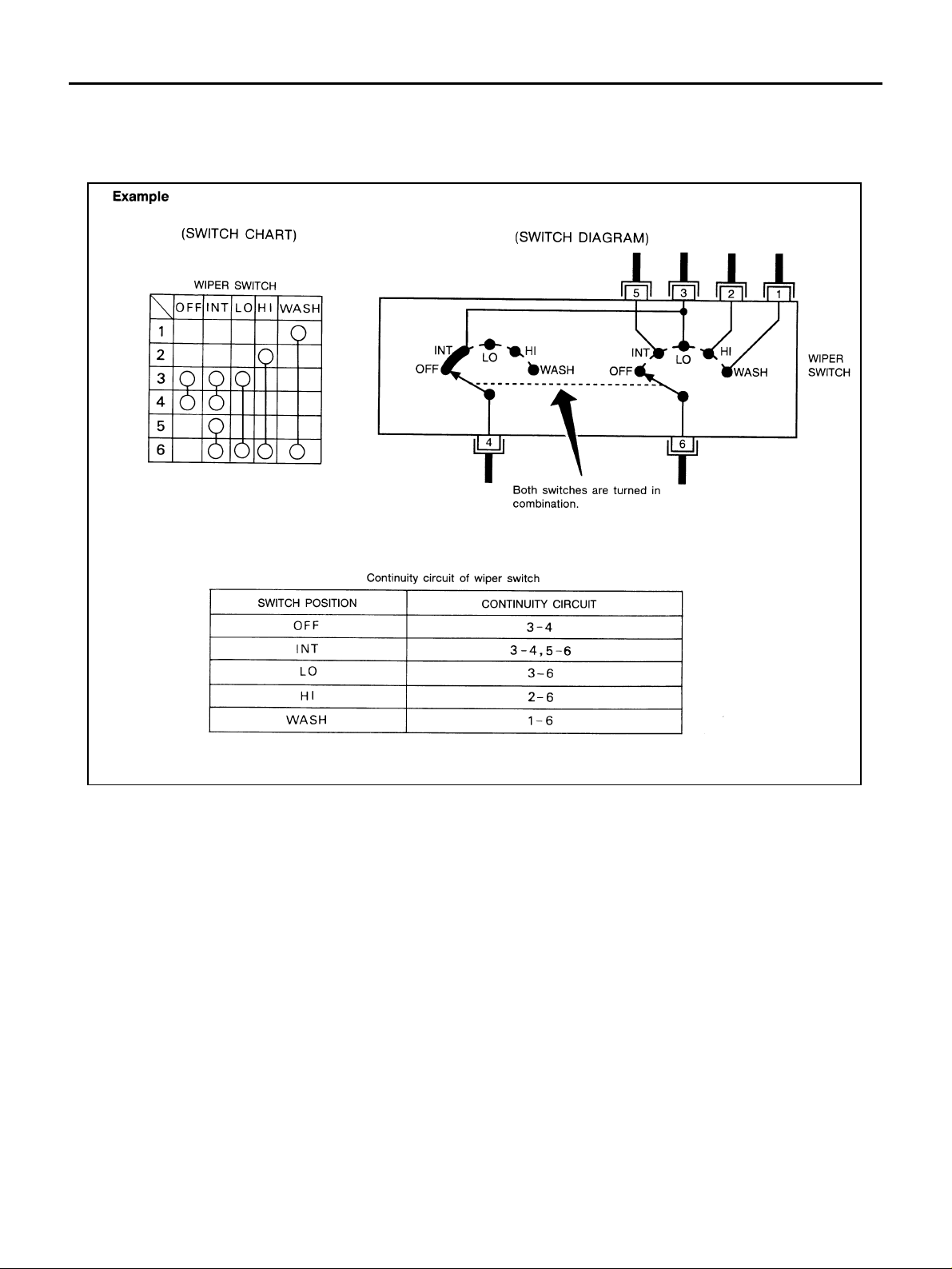
Multiple Switch
The continuity of multiple sw itch is described in two ways as sh own below.
● The switch ch art is used in schematic diagrams.
● The switch diagram is used in wiring diagrams.
SGI875
GI-20
Page 21
HOW TO USE THIS MANUAL
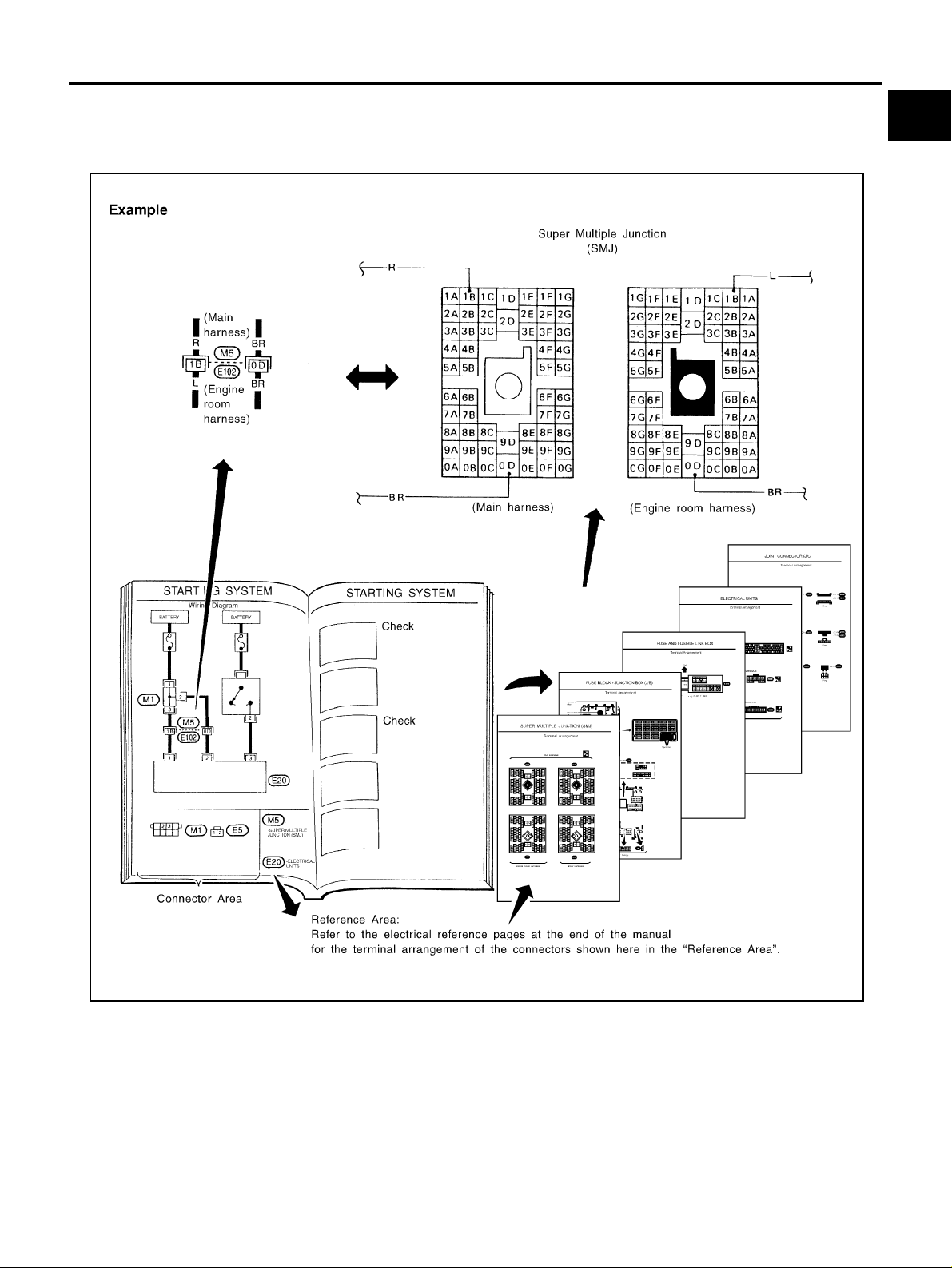
Reference Area
The Reference Area of the wiring diagram contains references to additional electrical reference pages at the
end of the manual. If connector numbers and titles are shown in the Reference Area of the wiring diagram,
these connector symbols are not shown in the Connector Area.
GI
B
C
D
E
F
G
SGI092A
H
I
J
K
L
M
GI-21
Page 22

HOW TO USE THIS MANUAL
Abbreviations
The followi ng ABBREVIATIONS are used:
ABBREVIATION DESCRIPTION
A/C Air Conditioner
A/T Automat ic Transaxle/Transmission
ATF Automatic Transmission Fluid
D
1 Drive range 1st gear
2 Drive range 2nd gear
D
3 Drive range 3rd gear
D
D
4 Drive range 4th gear
FR, RR Front, Rear
LH, RH Left-Hand, Right-Hand
M/T Manual Transaxle/Transmission
OD Overdrive
P/S Power Steering
SAE Society of Automotive Engineers, Inc.
SDS Service Data and Specifications
SST Special Service Tools
2WD 2-Wheel Drive
2 2nd range 2nd gear
2
1 2nd range 1st gear
2
2 1st range 2nd gear
1
1 1st range 1st gear
1
AAS0000R
GI-22
Page 23
SERVICE INFORMATION FOR ELECTRICAL INCIDENT
SERVICE INFORMATION FOR ELECTRICAL INCIDENT PFP:00000
How to Check Terminal AAS0000S
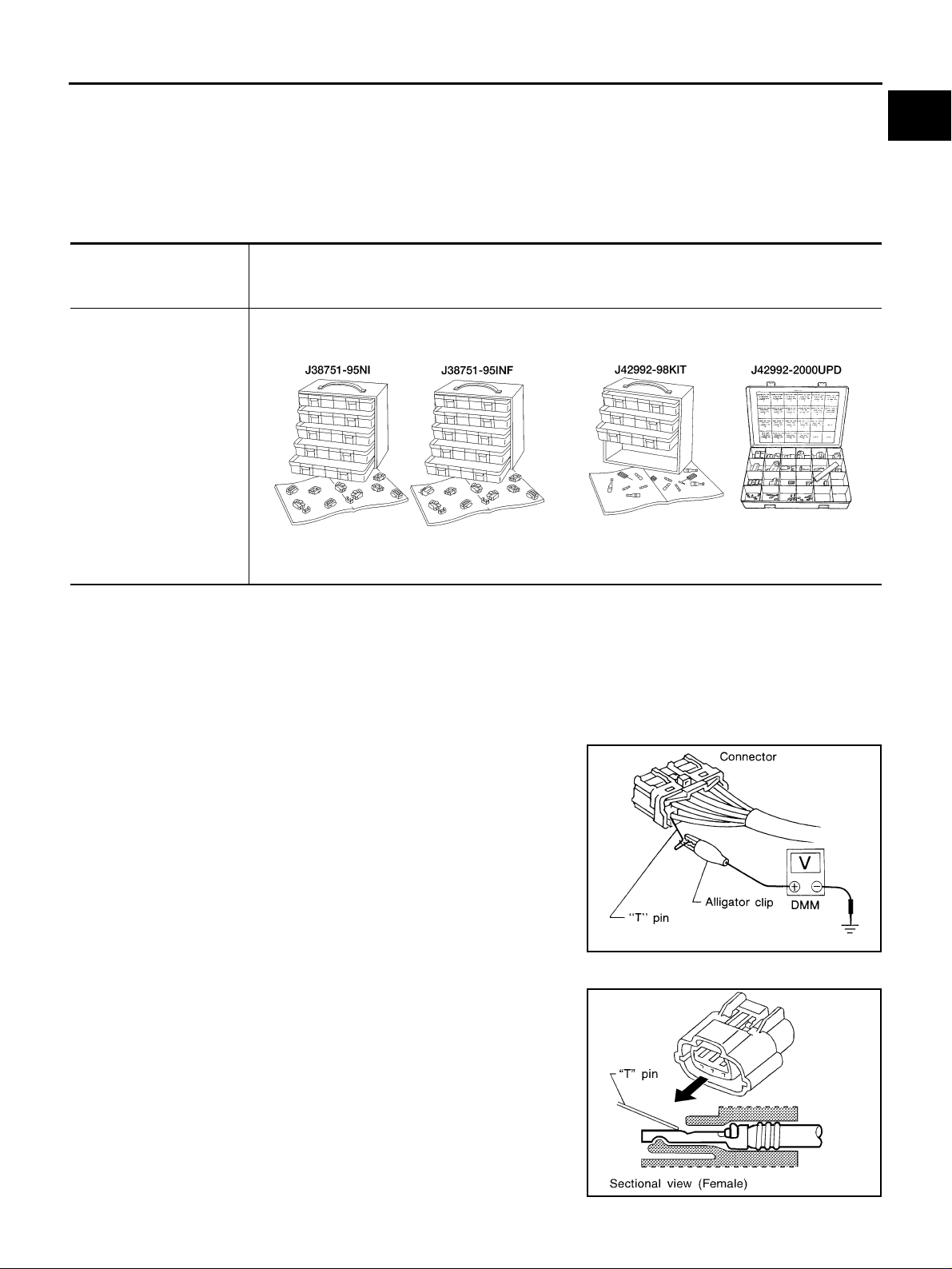
CONNECTOR AND TERMINAL PIN KIT
Use the connector and terminal pin kits listed below when replacing connectors or terminals.
The connector and terminal pin kits contain some of the most commonly used NISSAN/INFINITI connectors
and terminals. For detailed connector and terminal pin replacement procedures, refer to the latest NISSAN/
INFINITI CONNECTOR AND TERMINAL PIN SERVICE MANUAL.
Tool number
(Kent-Moore No.)
Tool name
(J38751-95NI)
Connector and terminal
pin kit (NISSAN)
(J38751-95INF)
Connector and terminal
pin kit (INFINITI)
(J42992-98KIT)
OBD and terminal repair
kit
(J42992-2000UPD)
OBD-II Connector Kit
Update
Description
WAIA0004E WAIA0005E
GI
B
C
D
E
F
G
H
HOW TO PROBE CONNECTORS
Connector damage and an intermittent connection can result from improperly probing of the connector during
circuit checks.
The probe of a digital multimeter (DMM) may not correctly fit the connector cavity. To correctly probe the connector, follow the procedures belo w using a “T” pin. For the b est contact grasp the “T” pin using an alligat or
clip.
Probing from Harness Side
Standard type (not waterproof type) connector should be probed
from harness side with “T” pin.
● If the connector has a rear cover such as a ECM connector,
remove the rear cover before probing the terminal.
● Do not probe waterproof connector from harness side. Damage
to the seal between wire and connector may result.
SGI841
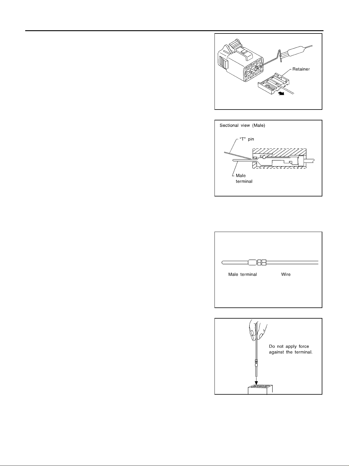
Probing from Terminal Side
FEMALE TERMINAL
● There is a small notch abov e each fe male te rminal. Pro be each
terminal with the “T” pin through the no tch.
Do not insert any ob ject other th an the same type male termin al
into female terminal.
I
J
K
L
M
GI-23
SEL265V
Page 24
SERVICE INFORMATION FOR ELECTRICAL INCIDENT
● Some connectors do not have a notch above ea ch terminal . To
probe each terminal, remove the connector retainer to make
contact space for prob ing.
MALE TERMINAL
Carefully pr obe the contact surface of each terminal using a “T” pin.
Do not bend terminal.
SEL266V
SEL267V
How to Check Enlarged Contact Spring of Terminal
An enlarged contact spring of a terminal may create intermittent signals in the circuit.
If the intermittent open circuit occurs, follow the procedure below to inspect for open wires and enlarged contact spring of female terminal.
1. Assemble a male terminal and approx. 10 cm (3.9 in) of wi re.
Use a male terminal which matches the female terminal.
2. Disconnect the suspected faulty connector and hold it terminal
side up.
SEL270V
3. While holding the wire of the male terminal, try to insert the male
terminal into the female terminal.
Do not force the male terminal into the female terminal with
your hands.
GI-24
SEL271V
Page 25
SERVICE INFORMATION FOR ELECTRICAL INCIDENT
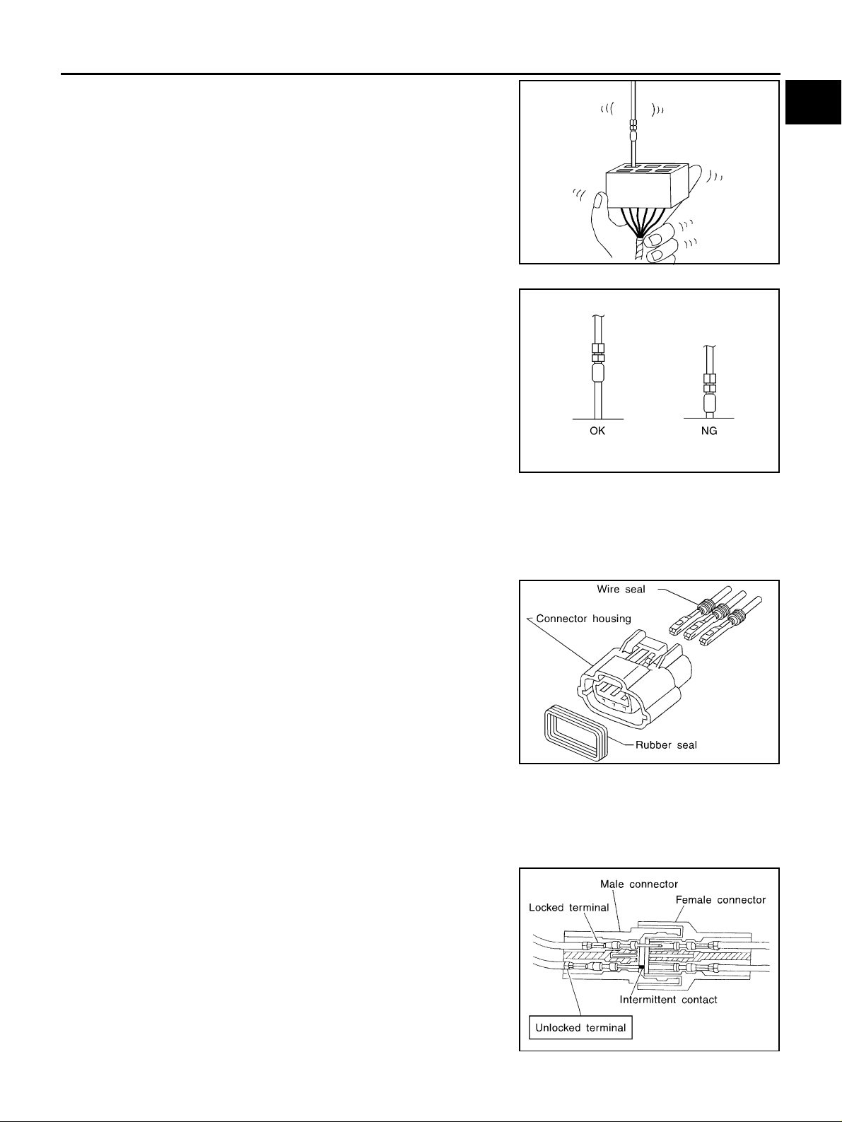
4. While moving the connector, check whether the male terminal
can be easily inserted or not.
● If the male terminal can be easily inserted into the female termi-
nal, replace the female terminal.
GI
B
C
SEL272V
D
E
F
G
SEL273V
Waterproof Connector Inspection
If water enters the connector, it can short interior circuits. This may lead to intermittent problems.
Check the following items to maintain the original waterproof characteristics.
RUBBER SEAL INSPECTION
● Most waterproof connectors are provided with a rubber seal
between the male and female connectors. If the seal is missing,
the waterpro of performance may not meet specifications.
● The rubber seal may come off when connectors are discon-
nected. Whenev er connectors are reco nnected, make sure the
rubber seal is properly installed on either side of male or female
connector.
SEL275V
WIRE SEAL INSPECTION
The wire seal mu st be installed o n the wire insertion ar ea of a wate rproof conn ector. Be sure that the sea l is
installed properly.
Terminal Lock Inspection
Check for unlocked terminals by pulling wire at the end of connector.
An unlocked terminal may create intermittent signals in the circuit.
H
I
J
K
L
M
GI-25
SEL330V
Page 26
SERVICE INFORMATION FOR ELECTRICAL INCIDENT
How to Perform Efficient Di agnosis for an Electrical Incident
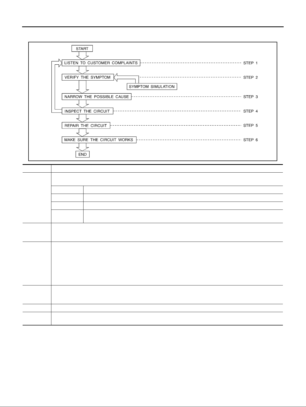
WORK FLOW
STEP DESCRIPTION
Get detailed information about the conditions and the environment when the incident occurred.
The following are key pieces of information required to make a good analysis:
WHAT Vehicle Model, Engine, Transmission/Transaxle and the System (i.e. Radio).
STEP 1
STEP 2
STEP 3
STEP 4
STEP 5 Repair or replace the incident circuit or component.
STEP 6
WHEN Date, Time of Day, Weather Conditions, Frequency.
WHERE Road Conditions, Altitude and Traffic Situation.
HOW
Operate the system, road test if necessary.
Verify the parameter of the incident.
If the problem cannot be duplicated, refer to “Inc id ent Simul ation Tests”.
Get the proper diagnosis materials tog eth er incl udi ng:
● Powe r Supply R out ing
● Syste m Operation Descriptions
● Applicable Service Manual Sections
● Chec k fo r any Servi ce Bull etins
Identify where to begin diagnosis base d upon your knowledge of the system operation and the cu st om er com m ents.
Inspect the system for mechanical bi nding, loo se connectors or wiring damage.
Determine which circuits and components are involved and diagnose using the Power Supply Routing and Harness
Layouts.
Operate the system in all modes. Verify the system works properly under all conditions. Make sure you have not inadvertently created a new incident during your diagnosis or repair steps.
System Symptoms, Operating Conditi ons (Ot her Components Interaction).
Service History and if any After Market Accessories have been installed.
AAS0000T
SGI838
INCIDENT SIMULATION TESTS
Introduction
Sometimes the symptom is not present when the vehicle is brought in for service. If possible, re-create the
conditions present at the time of the incident. Doing so may help avoid a No Trouble Found Diagnosis. The following section illustrates ways to simulate the conditions/environment under which the owner experiences an
electrical incident.
The section is broken into the six following topics:
● V ehicle vibration
● Heat sensitive
GI-26
Page 27
SERVICE INFORMATION FOR ELECTRICAL INCIDENT
● Freezing
● Water intrusion
● Electrical load
● Cold or hot start up
Get a thorough description of the incident from the customer. It is important for simulating the conditions of the
problem.
GI
B
Vehicle Vibration
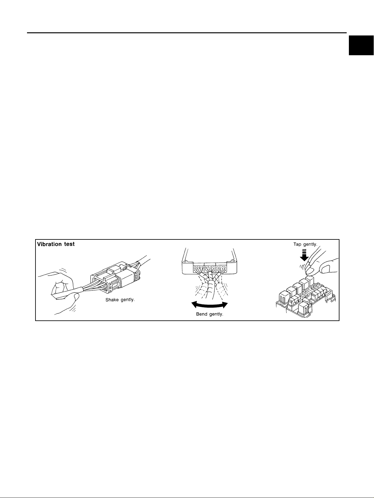
The problem may occu r or be com e wors e wh ile dr iving on a roug h road or whe n eng ine i s vibrat in g (idl e with
A/C on). In such a case , you w ill wan t to ch eck f or a vib rati on rel ated con ditio n. Re fer to th e foll owing i llu stration.
CONNECTORS & HARNESS
Determine which con necto rs an d wirin g ha rness woul d affect t he elec trical s yste m yo u are insp ecti ng. G entl y
shake each connect or and harness while monit oring the system for the inciden t you are trying to duplicate.
This test may indicate a loose or poor electrical connection.
HINT
Connectors can be exposed to moi sture. It is possibl e to get a thin film of corrosion on the co nnector terminals. A visual inspection may not reveal this without disconnecting the connector. If the problem occurs intermittently, perhaps the problem is ca used by corrosi on. It is a good i dea to disco nnect, inspec t and clean the
terminals on related connectors in the syste m .
SENSORS & RELAYS
Gently apply a slight vibration to sensors and relays in the system you are inspecting.
This test may indicate a loose or poorly mounted sensor or relay.
C
D
E
F
G
H
I
J
SGI839
ENGINE COMPARTMENT
There are several reasons a vehicle or engine vibration could cause an electrical complaint. Some of the
things to check for are:
● Connectors not full y se ate d.
● Wiring harness not long enough and is being st ressed due to engine vibrati ons or rocking.
● Wires laying across brackets or moving components.
● Loose, dirty or corroded ground wires.
● Wires routed too clos e to ho t components.
To inspect components under the ho od , st a r t by ve r ifyi n g t he i nt e gri t y of gr oun d con ne cti on s. (Re fe r t o Grou nd
Inspection described later.) First check that the system is properly grounded. Then check for loose connection
by gently shak ing the wiring or comp onents as previously explained. Using th e wiring diagrams inspe ct the
wiring for continuity.
BEHIND THE INSTRUMENT PANEL
An improperly routed or improperly clamped harness can become pinched during accessory installation. Vehicle vibration can aggravate a harness which is routed along a bracket or near a screw.
K
L
M
GI-27
Page 28
SERVICE INFORMATION FOR ELECTRICAL INCIDENT
UNDER SEATING AREAS
An unclamped or loose harness can cause wiring to be pinched by seat components (such as slide guides)
during vehicle vibrat ion. If the wiring runs under seating are as, inspect wire routing for possible damage or
pinching.
Heat Sensitive
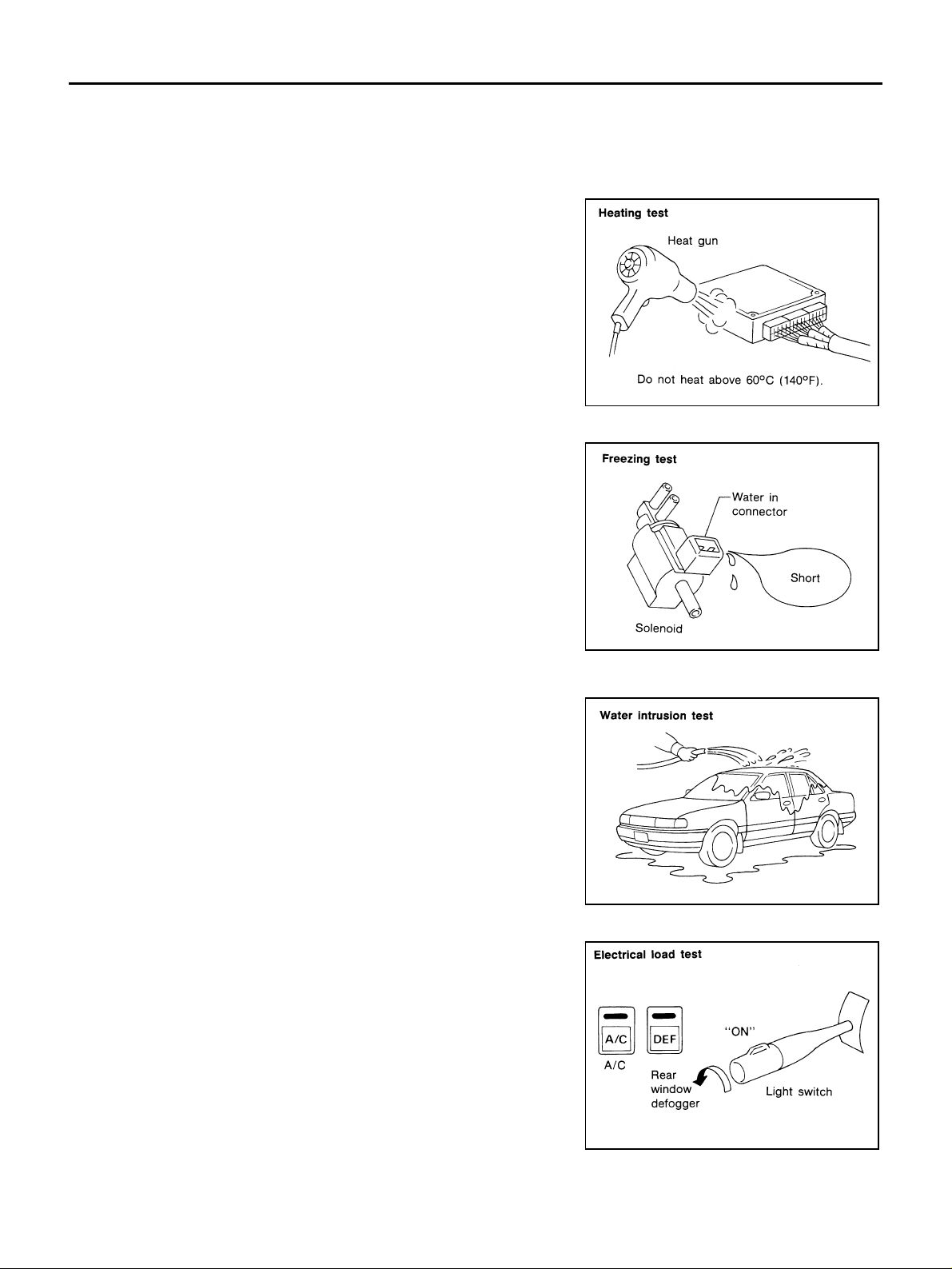
The customer's concern may occur during h ot weather or after car
has sat for a short time. In such cases you will want to check for a
heat sensitiv e condition.
To determine if an electrical component is heat sensitive, heat the
component with a heat gun or equivalent.
Do not heat compo nents above 60°C (140°F). If incident occurs
while heating th e unit, either repla ce o r p rop erly insulate the c om p onent.
SGI842
Freezing
The customer may indicate the incident goes away after the car
warms up (wint e r tim e) . T he c au se co ul d be r el a ted to wa te r fr ee zi ng
somewhere in the wiring/electrical system.
There are two me thods to check for this. The first is to arra nge for
the owner to leave his car overnight. Make sure it will get cold
enough to demonstrate his complaint. Leave the car parked outside
overnight. In the morning, do a quick and thorough diagnosis of
those electrical components which could be affected.
The second m ethod is to put the sus pect component int o a freezer
long enough for any water to freeze. Reinstall the part into the car
and check for the re occurrence of the inci dent. If it o ccurs, repair or
replace the compone nt .
SGI843
Water Intrusion
The incident may occur only during high humidity or in rainy/snowy
weather. In such cases the in cident could be c aused by wa ter intrusion on an electrical part. This can be simulated by soaking the car
or running it through a car wash.
Do not spray water directly on any electrical components.
Electrical Load
The incident may be electrical load sensitive. Perform diagnosis with
all accessories (including A/C, rear window defogger, radio, fog
lamps) turned on.
SGI844
SGI845
GI-28
Page 29
SERVICE INFORMATION FOR ELECTRICAL INCIDENT
Cold or Hot Start Up
On some occas ions an elec trical incide nt may occur on ly when the ca r is started col d, or it may oc cur when
the car is restarted hot shortly after being turned off. In these cases you may have to keep the car overnight to
make a proper diagno sis.
CIRCUIT INSPECTION
Introduction
In general, testing electrical circuits is an easy task if it is approached in a logical and organized method.
Before beginning it is important to have all available information on the system to be tested. Also, get a thorough understanding of system opera tion. Then you will be able to use the approp riate equipm ent and follow
the correct test procedure.
You may have to simula te ve hicl e vib ration s whil e test in g elec trical c ompo nents. Ge ntl y shak e the w irin g harness or electrical component to do this.
GI
B
C
D
OPEN
SHORT
A circuit is open when there is no continuity through a section of the circui t.
There are two types of shorts.
● SHORT CIRCUIT
● SHORT TO GROUND When a circuit contacts a ground source and gr ounds the circuit.
When a circuit contacts another circuit and causes the norm al resistanc e to
change.
NOTE:
Refer to “How to Check Terminal” to probe or check terminal.
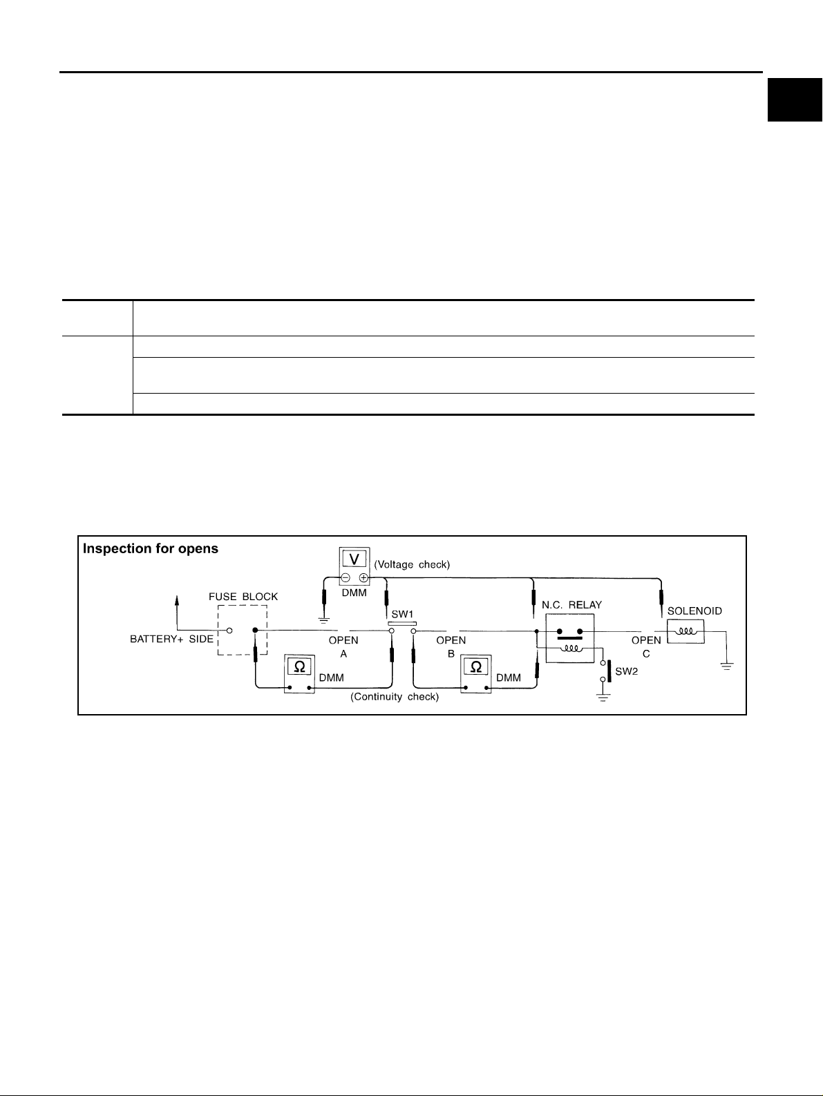
Testing for “Opens” in the Circuit
Before you begin to diagnose and test the system, you should rough sketch a schematic of the system. This
will help you to logically walk through the diagnosis process. Drawing the sketch will also reinforce your working knowledge of the system.
SGI846-A
E
F
G
H
I
J
K
L
CONTINUITY CHECK METHOD
The continuity check is used to find an open in the circuit. The digital multimeter (DMM) set on the resistance
function will indicate an open circuit as over limit (no beep tone or no ohms symbol). Make sure to always start
with the DMM at the highest resistance level.
To help in understanding the diagnosis of open circuits, please refer to the previous schematic.
● Disconnect the ba tte ry ne gative cable.
● Start at one end of the circuit and work your way to the other end. (At the fuse block in this example)
● Connect one probe of the DMM to the fuse block terminal on the load side.
● Connect the ot her probe to the fuse b lock (power) side of SW1. Little or no resis tance will indicate th at
portion of the circuit has good continuity. If there were an open in the circuit, the DMM would indicate an
over limit or infinite resistance condition. (point A)
● Connect the prob es be tw ee n SW 1 an d th e re la y. Little or no resistance wil l ind ic at e th at p ort ion of th e c ir-
cuit has good conti nuity. If there were an open in the circuit, the DMM would in dicate an over limi t or infinite resist ance condition. (point B)
● Connect the probes between the relay and the solenoid. Little or no resistance will indicate that portion of
the circuit ha s g oo d co nt inu it y. If there were an op en in the ci r cu it, th e DM M wo ul d i n dica te an ov er l i mit o r
infinite resi stance condition. (point C)
Any circuit can be diagnosed using the approach in the previous example.
GI-29
M
Page 30
SERVICE INFORMATION FOR ELECTRICAL INCIDENT
VOLTAGE CHECK METHOD
To help in understand ing the diagnosis of open circuits please ref er to the previous schematic.
In any powered circu it, an open can b e fou nd by method ical ly ch ecki ng the syste m for t he p res ence of volt a ge.
This is done by switching the DMM to the voltage function.
● Connect o ne probe of the DMM to a known good ground.
● Begin probing at one end of the circuit and work your way to the other end.
● With SW1 open, probe at SW1 to check for voltage.
voltage; open is further down the circuit than SW1.
no voltage; open is between fuse block and SW1 (point A).
● Close SW1 and probe at relay.
voltage; open is furth er down the circuit than the relay.
no voltage; open is between SW1 and relay (point B).
● Close the relay and probe at the solenoid.
voltage; open is further down the circuit than the solenoid.
no voltage; open is between relay and solenoid (point C).
Any powered circuit can be diagnosed using the approach in the previous example.
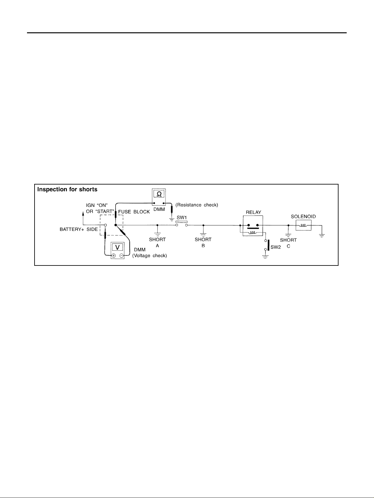
Testing for “Shorts” in the Circuit
To simplify the discussion of shorts in the system, please refer to the following schematic.
SGI847-A
RESISTANCE CHECK METHOD
● Disconnect the battery negative cable and remove the blown fuse.
● Disconnect all loads (SW1 open, relay disconnected and solenoid disconnected) powered through the
fuse.
● Connect one probe of the DMM to the load side of the fuse terminal. Connect the other probe to a known
good ground.
● With SW1 open, check for continuity.
continuity; short is between fuse terminal and SW1 (point A).
no continuity; short is further down the circuit than SW1.
● Close SW1 and disconn ect the relay. Put probes at the load side of fuse terminal and a known good
ground. Then, check for continuity.
continuity; short is between SW1 and the relay (point B).
no continuity; short is further down the circuit than the relay.
● Close SW1 and jump the rela y contacts with jumper wire. Put probes at the load si de of fuse terminal and
a known good ground. Then, check for continuity.
continuity; short is between relay and solenoid (po int C).
no continuity; check solenoid, retrace steps.
VOLTAGE CHECK METHOD
● Remove the bl own fus e and d is con ne ct al l loa ds (i. e. SW 1 ope n, rel ay d is con nect e d an d sole no id di scon-
nected) powered through the fuse.
● Turn the ignition key to the O N or START position. Verify battery voltage at the ba ttery + s ide of the fuse
terminal (on e l ead on th e b at ter y + term in al side of th e fus e b lo ck a nd on e lead on a kn own goo d g rou nd ).
● With SW1 open and the DMM leads across both fuse terminals, check for voltage.
voltage; short is between fuse block and SW1 (point A).
GI-30
Page 31
SERVICE INFORMATION FOR ELECTRICAL INCIDENT
no voltage; short is further down the cir c uit than SW1.
● With SW1 closed, relay and solenoid disconnected and the DMM leads across both fuse terminals, check
for voltage.
voltage; short is between SW1 and the relay (point B).
no voltage; short is further down the circuit than the r elay.
● With SW1 closed, relay contacts jumped with fused jumper wire check for voltage.
voltage; short is down the circuit of the relay or between the relay and the disconnected solenoid (point C).
no voltage; retrace steps and check power to fuse block.
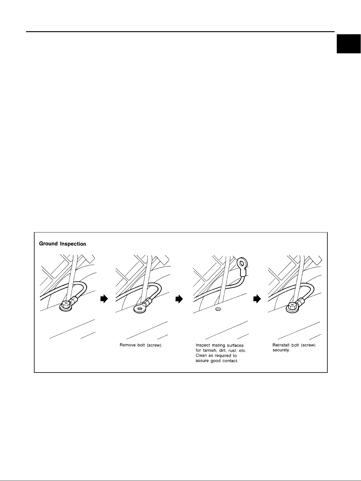
Ground Inspection
Ground connections are very important to the proper operation of electrical and electronic circuits. Ground
connections are often exposed to moisture, dirt and other corrosive elements. The corrosion (rust) can
become an unwant ed resistanc e. This unwanted resistance can change the way a circuit works.
Electronical ly cont rol l ed ci rcui t s a r e ve ry se ns it ive to prop er gr ou ndin g. A lo ose or co r rod ed gro un d ca n d rast ically affect an elec tronically controlled circui t. A poor or corroded ground c an easily affect the circuit. Eve n
when the groun d connection looks clean, ther e can be a thin film of rust on the surface.
When inspecting a ground connection follow these rules:
● Remove the ground bolt or screw.
● Inspect all mating surfaces for tarnish, dirt, rust, etc.
● Clean as required to assure good contact.
● Reinstall bolt or screw securely.
● Inspect for “add-on” accessories which may be interferi ng with the ground circuit.
● If several wires are crimped into one ground eyelet terminal, check for proper crimps. Make sure all of the
wires are clean, securely fastened and providing a good ground path. If multiple wires are cased in one
eyelet make sure no ground wires have excess wire insulation.
For detailed ground distribution information, refer to “Ground Distribution” in PG section.
GI
B
C
D
E
F
G
H
SGI853
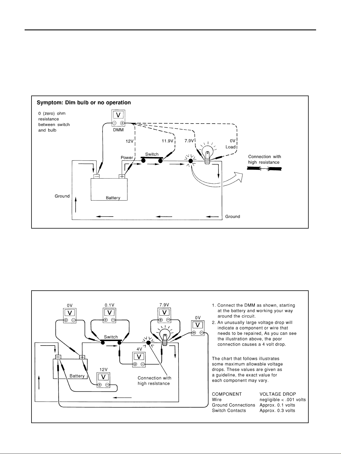
Voltage Drop Tests
Voltage drop tests are often used to find co mponents or circuits whic h have excessiv e resistance. A voltage
drop in a circuit is caused by a resistance when the circuit is in operation.
Check the wire in the illustration. When measuring resistance with DMM, contact by a single strand of wire will
give reading of 0 ohms. This would indicate a good circuit. When the circuit operates, this single strand of wire
is not able to carry the current. The single strand will have a high resistance to the current. This will be picked
up as a slight voltage drop.
Unwanted resistance can be caused by many situations as follows:
● Undersized wiring (single strand example)
● Corrosion on switch contacts
● Loose wire connec tions or splices.
I
J
K
L
M
GI-31
Page 32
SERVICE INFORMATION FOR ELECTRICAL INCIDENT
If repairs are needed always use wire that is of the same or larger gauge.
MEASURING VOLTAGE DROP — ACCUMULATED METHOD
● Connect the DMM ac ross the co nnector or part of the circ uit you wa nt to check. The posit ive lead of t he
DMM should be closer to power and the negative lead closer to ground.
● Operate the circuit.
● The DMM will indicate how many volts are being used to “push” current through that part of the circuit.
Note in the illustration that there is an excessive 4 .1 volt drop between the battery and the bu lb.
SGI974
MEASURING VOLTAGE DROP — STEP-BY-STEP
The step-by-step method is most useful for isolating excessive drops in low voltage systems (such as those in
“Computer Controlled Systems”).
Circuits in the “Computer Controlled System” operate on very low amperage.
The (Computer Controlled) system operations can be adversely affected by any variation in resistance in the
system. Such resistance variation may be caused by poor connection, improper installation, improper wire
gauge or corros ion.
The step by step v oltage drop test can identify a component or wire with too much resistance.
GI-32
SAIA0258E
Page 33
SERVICE INFORMATION FOR ELECTRICAL INCIDENT
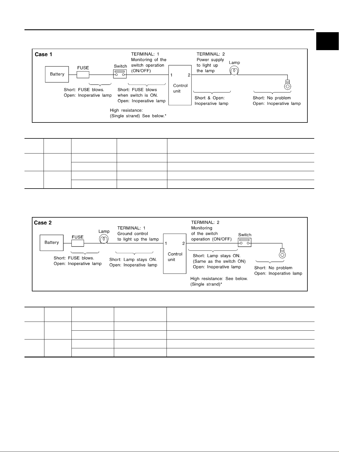
Control Unit Circuit Test
System Description:When the switch is ON, the control unit lights up the lamp.
GI
B
C
D
MGI034A
INPUT-OUTPUT VOLTAGE CHART
Pin
No.
1 Switch
2Lamp
The voltage value is based on the body ground.
*:If high resistance exists in the switch side circu it (caused by a single stran d), terminal 1 doe s not detect ba ttery voltage. Control unit
does not detect the s witch is ON even i f the switch does n ot turn ON . Therefore, the contro l unit doe s not su pply power t o light up the
lamp.
Item C ondition
Switch ON Battery voltage Lower than battery voltage Approx. 8 (Example)
Switch OFF Approx. 0 Approx. 0
Switch ON Battery voltage Approx. 0 (Inoperative lamp)
Switch OFF Approx. 0 Approx. 0
Voltage
value [V]
In case of high resistance such as single strand [V ] *
MGI035A
E
F
G
H
I
J
K
L
INPUT-OUTPUT VOLTAGE CHART
Pin
No.
1 Lamp
2Switch
The voltage value is based on the body ground.
*:If high resistance exists in the swi tch side circuit ( caused by a s ingle stran d), ter minal 2 does not dete ct approx. 0V. Control unit d oe s
not detect the switch is ON even if the switch does not turn O N. Ther ef ore , the cont r ol unit does not control ground to light up the lamp.
Item Condition
Switch ON Approx. 0 Battery voltage (Inoperative lamp)
Switch OFF Battery voltage Battery voltage
Switch ON Approx. 0 Higher than 0 Approx. 4 (Example)
Switch OFF Approx. 5 Approx. 5
Voltage
value [V]
In case of high resistance such as single strand [V] *
GI-33
M
Page 34
SERVICE INFORMATION FOR ELECTRICAL INCIDENT
Control Units and Electrical Parts
PRECAUTIONS
● Never reverse polarity of battery terminals.
● Install only parts specified for a vehicle.
● Before replacing the control unit , check the input and output and
functions of the component parts.
● Do not apply excessive force when disconnecting a connector.
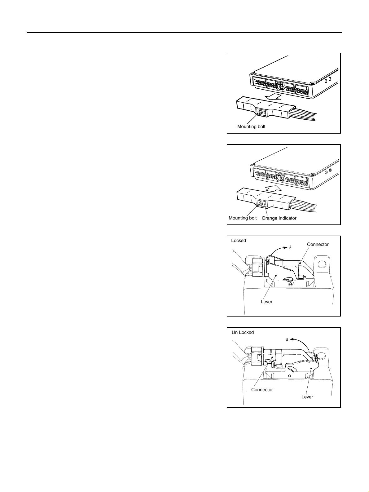
● If a connector is ins talled by tigh tenin g bo lts, loos en bo lt mo unt-
ing it, then take it out by hand.
● Before installing a connecto r, make sure the terminal is not ben t
or damaged, and then correc t ly conne c t it .
When installing a con nector by tightening bolts, fix it b y tightening the mount ing bolt u ntil the pain ted projec tion of th e connec tor becomes even with the surface.
AAS000A3
SAIA0251E
● For removal of the l ever type connector, pull the leve r up to th e
direction pointed to by the arrow A in the figure, and then
remove the connector.
● For installation of the lever type connector, pull down the lever to
the direction poin ted by the ar row B in th e figure , and the n push
the connector until a clicking noise is heard.
SAIA0252E
SAIA0253E
GI-34
SAIA0254E
Page 35
SERVICE INFORMATION FOR ELECTRICAL INCIDENT
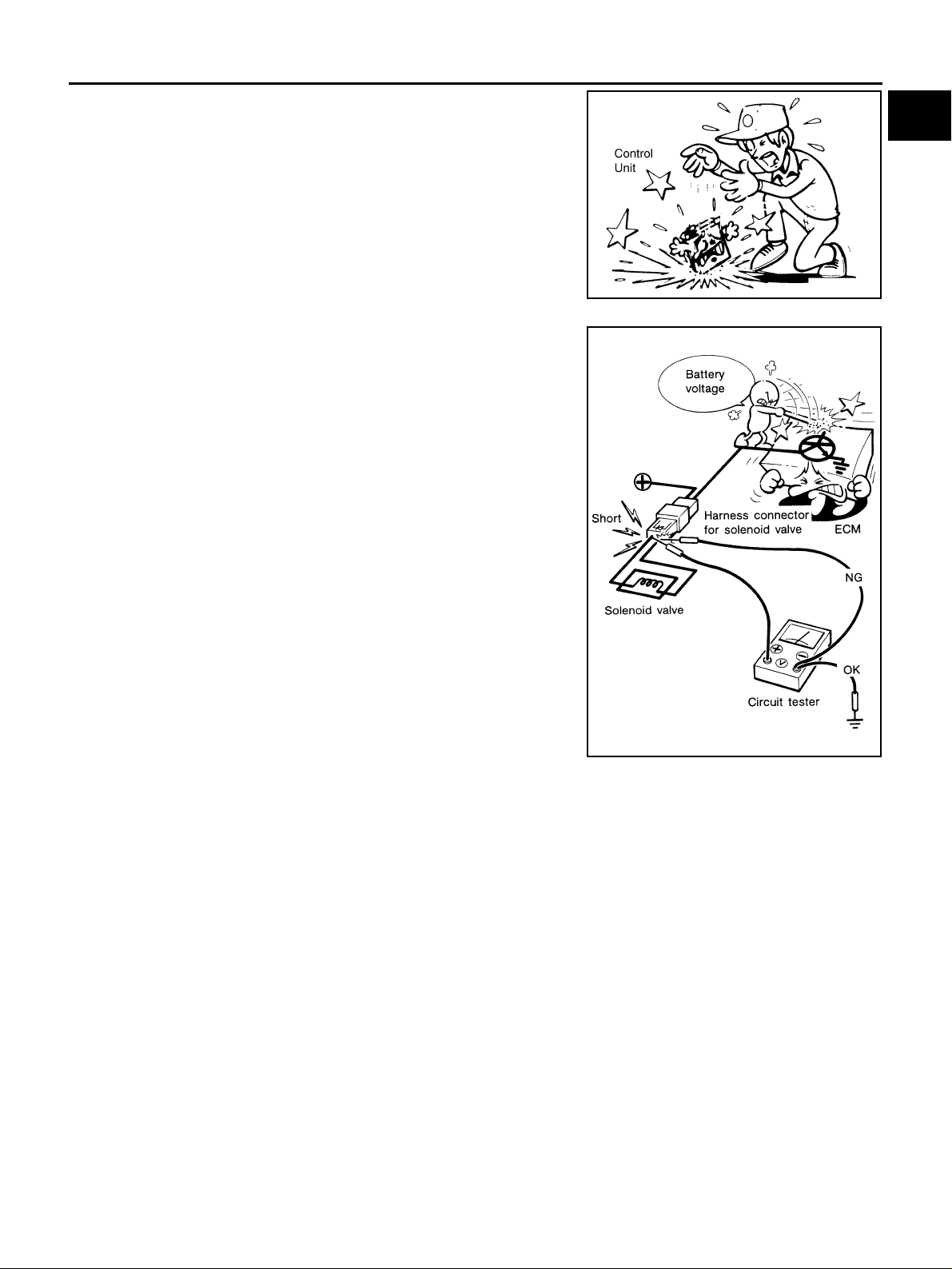
● Do not apply excessive shock to the control unit by dropping or
hitting it.
● Be careful to prevent condensation in the control unit due to
rapid temperatur e c ha ng es an d do not let water or rain get o n it .
If water is found in the control unit, dry it fully and then install it in
the vehicle.
● Be careful not to let oil to get on the control unit connector.
● Avoid clea ning the control unit with vola tile oil.
● Do not disassemble the control unit, and do not remove the
upper and low er covers.
● When using a DMM, be careful not to let test probes get close to
each other to prevent the power transistor in the control unit
from damaging battery voltage because of short circuiting.
● When checking input and output signals of the control unit, use
the specified check adapter.
GI
B
C
SAIA0255E
D
E
F
G
SEF348N
H
I
J
K
L
M
GI-35
Page 36

CONSULT-II CHECKING SYSTEM
CONSULT-II CHECKING SYSTEM
PFP:00000
Description AAS0000V
● CONSULT-II is a h and- hel d type t est er. When it is connected wit h a di agnost ic co nnec tor eq uipp ed on the
vehicle side, it will communicate with the control unit equipped in the vehicle and then enable various
kinds of diagnosti c tes ts.
● Refer to “CONSULT-II Software Operation Manual” for more information.
Function and Sys tem Application AAS0000W
Diagnostic test
mode
Work support
Self-diagnostic
results
Trouble diagnostic
record
Data monitor Input/Output data in the ECM can be read. x x x × -xx-
CAN diagnosis
support monitor
Active test
DTC confirmation
DTC work support Select the operating condition to confirm Diagnosis Trouble Codes. - x - - - - - ECM part number ECM part number can be read. x x x × -x--
ECU discriminated
No.
Function test
Control unit initialization
Configuration
x: Applicable
*:IVIS(NATS) [INFINITI Vehicle Immobilizer System (Nissan Anti-theft System)]
Note
This mode enables a technician to adjust som e devices faster and
more accurately by following the indicat ion s on CO N S ULT-II.
Self-diagnostic results can be read and erased quickly. x x x × xxxx
Current self-diagnostic results and all trouble diagnostic records
previously stored can be read.
Indicates the communication condi tion of CAN communication line. x x x x - x x -
Diagnostic Test Mode in which CONSULT-II drives some actuators
apart from the ECMs and also shifts some parameters in a specified
range.
The results of SRT (System Readiness Test) and the self-diagnosis
status/result can be confirmed.
Classification number of a replacement ECU can be read to prevent
an incorrect ECU from being installed.
Conducted by CONSULT-II instead of a technician to determine
whether each system is “OK” or “NG”.
All registered ignition key IDs in NATS components can be initialized and new IDs can be registered.
Function
—-----x--
A/T
ENGINE
ABS (Including VDC)
AIR PRESSURE MONITOR
x-x× -x--
----x---
x-x- -xx-
x-------
----x---
xxx -x - - -
-------x
AIR BAG
BCM
IPDM E/R
IVIS(NATS)*
NOTE:
This item is indicated, but it is what it does not use.
Nickel Metal Hydride Battery Replacement AAS0000X
CONSULT-II contains a nickel metal hydride battery. When replacing the battery obey the following:
WARNING:
Replace the nickel metal hydride battery with Genuine CONSULT-II battery only. Use of another battery may present a risk of fire or explosion. The battery may present a fire or chemical burn hazard if
mistreated. Do not recharge, disassemble or dispose of in fire.
Keep the battery out of reach of children and discard used battery conforming to the local regulations.
GI-36
Page 37
CONSULT-II CHECKING SYSTEM
Checking Equipment AAS0000Y
When ordering the following equipment, contact your NISSAN/INFINITI distributor.
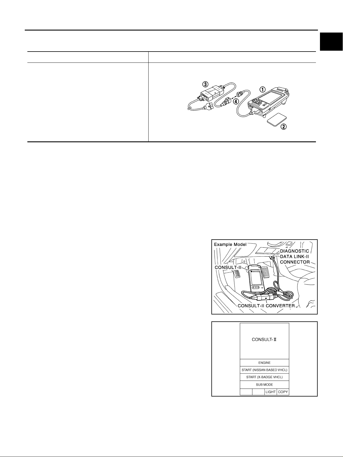
Tool name Description
NISSAN CONSULT-II
1.CONSULT-II unit (Tester internal soft: Resident
version 3.3.0) and accessories
2.Program card AED03E and AEN02C (For NATS)
3.CONSUL T-II CONVERTER
4.“CONSULT-II Pigtail” Cable
GI
B
C
D
SAIA0363E
NOTE:
● The CONSULT-II must be used in conjunction with a program card.
CONSULT-II does not require loading (Initialization) procedure.
● Be sure the CONSULT-II is turned off before installing or removing a program card.
CAUTION:
● If CONSULT-II is used with no connection of CONSULT-II CONVERTER, malfunctions might be
detected in self-diagnosis depending on control unit which carry out CAN communication.
● If CONVERTER is not connected with CONSULT-II, vehicle occur the "FAIL SAFE MODE" which is
"LIGHT UP the HEAD LIGHT" and/or "COOLING FAN ROTATING" when CONSULT-II is started.
● Previous CONSULT-II “I” and “Y” DLC-I and DLC-II cables should NO T be used a nymore beca use
their DDL connectors pins can be damaged during cable swapping.
CONSULT-II Start Procedure AAS000A1
1. Turn off the ignition switch.
2. Connect CONSULT-II and CONSULT-II CONVERTER to the
data link co nnector.
E
F
G
H
I
J
K
L
3. Turn on the ignition switch.
4. Touch "START(NISSAN BASED VHCL)" or "System shortcut"
(eg: ENGINE) on the screen.
GI-37
PAIA0070E
M
SAIA0450E
Page 38
CONSULT-II CHECKING SYSTEM
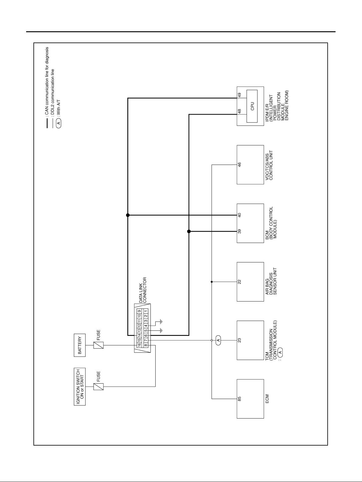
CONSULT-II Data Link Connector (DLC) Circuit
AAS000A0
GI-38
TAWT0019E
Page 39

CONSULT-II CHECKING SYSTEM
INSPECTION PROCEDURE
If the CONSULT-II cannot diagnose the system properly, check the following items.
Symptom Check item
CONSULT-II cannot access
any system.
CONSULT-II cannot access
individual system. (Other systems can be accessed.)
NOTE:
The DDL1 and DDL2 circuits from DLC pins 12, 13, 14 and 15 may be connected to mo re than one syste m . A
short in a DDL circuit connected to a control unit in one system may affect CONSULT-II access to other systems.
● CONSULT-II DLC power supply circuit (Terminal 8) and ground circuit (Terminal 4) (For detailed
circuit, refer to “MIL & Data Link Connectors Wiring Diagra m” in EC section.)
● CONSULT-I I DLC cable and CONSULT-II CONVERTER.
● CON S ULT-II program card (Check the appropriate CONSULT-II program card for the system.
Refer to "Checking Equipment".)
● Power supp ly an d grou nd ci rc uit fo r the cont rol unit of the syst em (For detailed circui t , refer to wir-
ing diagram for each system.)
● Open or short circuit between the system and CONSULT-II DLC (For detailed circuit, refer to wiring
diagram for each system.)
● Open or shor t circ ui t CAN communication line. Refer to LAN-2, "Precautions When Using CON-
SULT-II" .
GI
B
C
D
E
F
G
H
K
M
I
J
L
GI-39
Page 40
LIFTING POINT
LIFTING POINT
PFP:00000
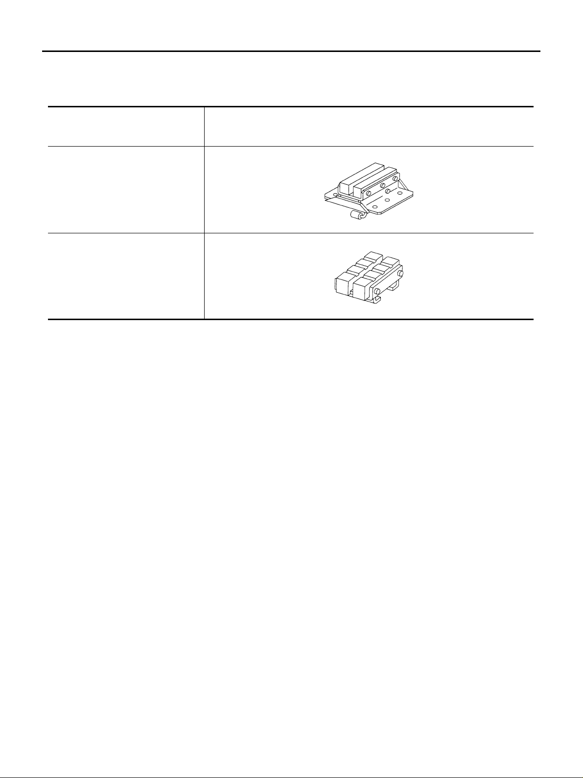
Special Service Tools AAS00010
The actual shapes of Kent-Moore tools may differ from those of special service tools illustrated here.
Tool number
(Kent-Moore No.)
Tool name
LM4086-0200
( - )
Board on at tachment
LM4519-0000
( - )
Safety stan d attachmen t
CAUTION:
● Every time the vehicle is lifted up, maintain the complete vehicle curb condition.
● Since the vehicle's center of gravity change s w he n remo vi ng ma in parts on the front side (engine,
transmission, suspension etc.), support a jack up point on the rear side garage jack with a mission
jack or equivalent.
● Since the veh icle's cen ter o f grav it y chan ges when remov ing m ain p arts on the rear side (rear a xle ,
suspension, etc.), support a jack up point on the front side garage jack with a mission jack or
equivalent.
● Be careful not to smash or do not do anything that would affect piping parts.
Description
S-NT001
S-NT002
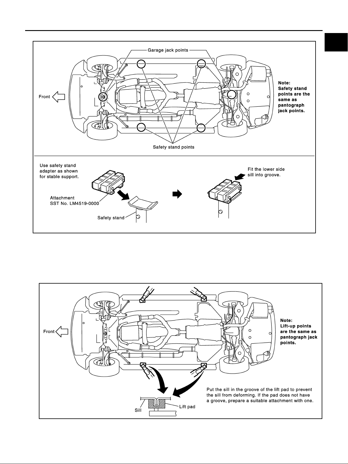
Garage Jack and Safety Stand AAS00011
WARNING:
● Park the vehicle on a level surface when using the jack. Make sure to avoid damaging pipes,
tubes, etc. under the vehicle.
● Never get under the ve hic le while it is supported only by the ja ck . Always use safety stands when
you have to get under the vehicle.
GI-40
Page 41
LIFTING POINT
● Place wheel chocks at both front and back of the wheels on the ground.
GI
B
C
D
E
F
G
PAIA0045E
2-pole Lift AAS00012
WARNING:
When lifting the vehicle, open the lift arms as wide as possible and ensure that the front and rear of
the vehicle are well balanced.
When setting the li ft arm, do not all ow the arm to contact the brake tu bes, brake cable, fue l lines and
sill spoiler.
H
I
J
K
L
M
GI-41
PAIA0046E
Page 42
LIFTING POINT
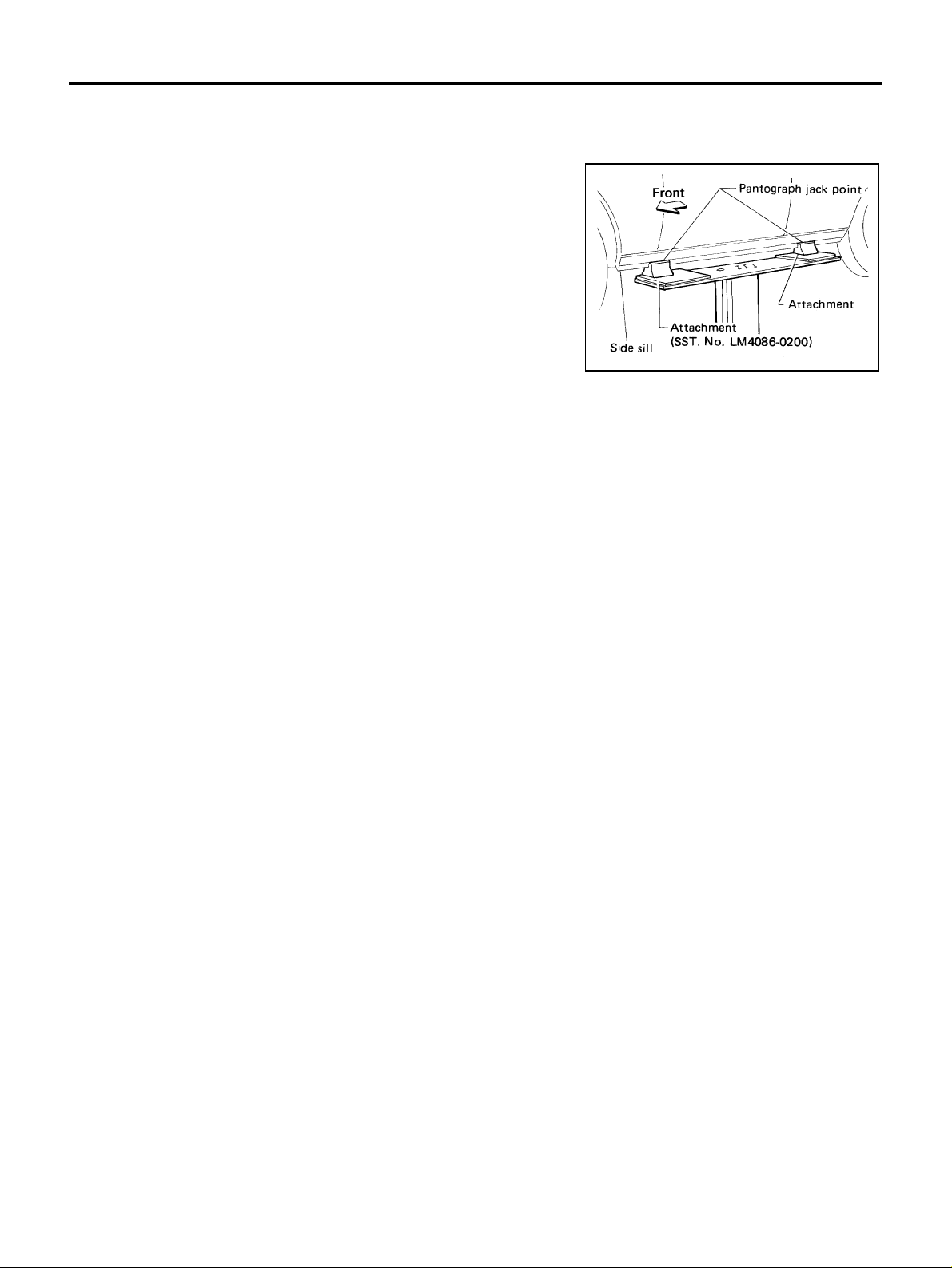
Board-on Lift
CAUTION:
Make sure vehicle is empty when lifting.
● The board-on lift attachment (LM4086- 0200) se t at fro nt end
of vehicle should be set on the front of the sill under the
front door opening.
● Position attachments at front and rear ends of board-on lift.
AAS00013
AGI016
GI-42
Page 43
TOW TRUCK TOWING
TOW TRUCK TOWING PFP:00000
Tow Truck Towing AAS00014
CAUTION:
● All applicable state or Provincial (in Ca nada) laws and local laws rega rding the towing operation
must be obeyed.
● It is necessary to us e proper towing equipment to avoid possible damage to the vehicle duri ng
towing operation. Towing is in accordance with Towing Procedure Manual at dealer.
● Always attach safety chains before towing.
● When towing, make sure that the transmission, steering system and power train are in good order.
If any unit is damaged, dollies must be used.
● Never tow an automa tic transmissio n model from the rear (that is ba ckward) with four whee ls on
the ground. This may cause serious and expensive damage to the transmission.
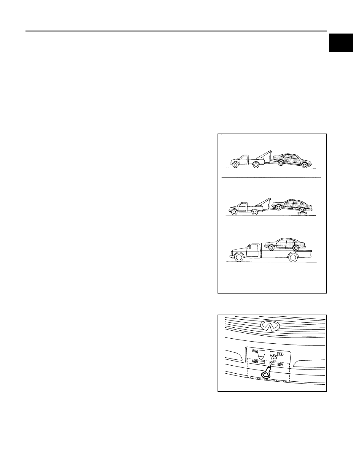
INFINITI recommends that the vehicle be towed with the driving
(rear) wheels off the ground as illustrated.
CAUTION:
● When towing with the front whe els on the ground (If a tow-
ing dollies does not be used), turn the ignition key to the
OFF position, and secure the steering wheel in the straightahead position with a rope or similar device. Never place
the ignition key in the LOCK position. This will result in
damage to the steering lock mechanism.
GI
B
C
D
E
F
G
SGI065A
Vehicle Recovery (Freein g a Stuck Vehicle) AAS00015
FRONT
● After removing the front licence plate (or the bumper cover),
securely install the towing hook.
Then reinstall the license plate on the lower fitting point.
● Tow chains or cables mus t be attached only to the main struc-
tural members of the vehicle.
● Pulling devices should be routed so they do not touch any part
of the suspensi on, steering, brake or cooling systems.
● Always pull th e cable straight out from the f ront or rear of the
vehicle. Never pull on the vehicle at an angle.
● Pulling devices such as ropes or canvas straps are not recom-
mended for use in vehicle towing or recovery.
● Stand clear of a stuck vehicle.
PAIA0047E
H
I
J
K
L
M
REAR
● Towing hook is not available.
GI-43
Page 44
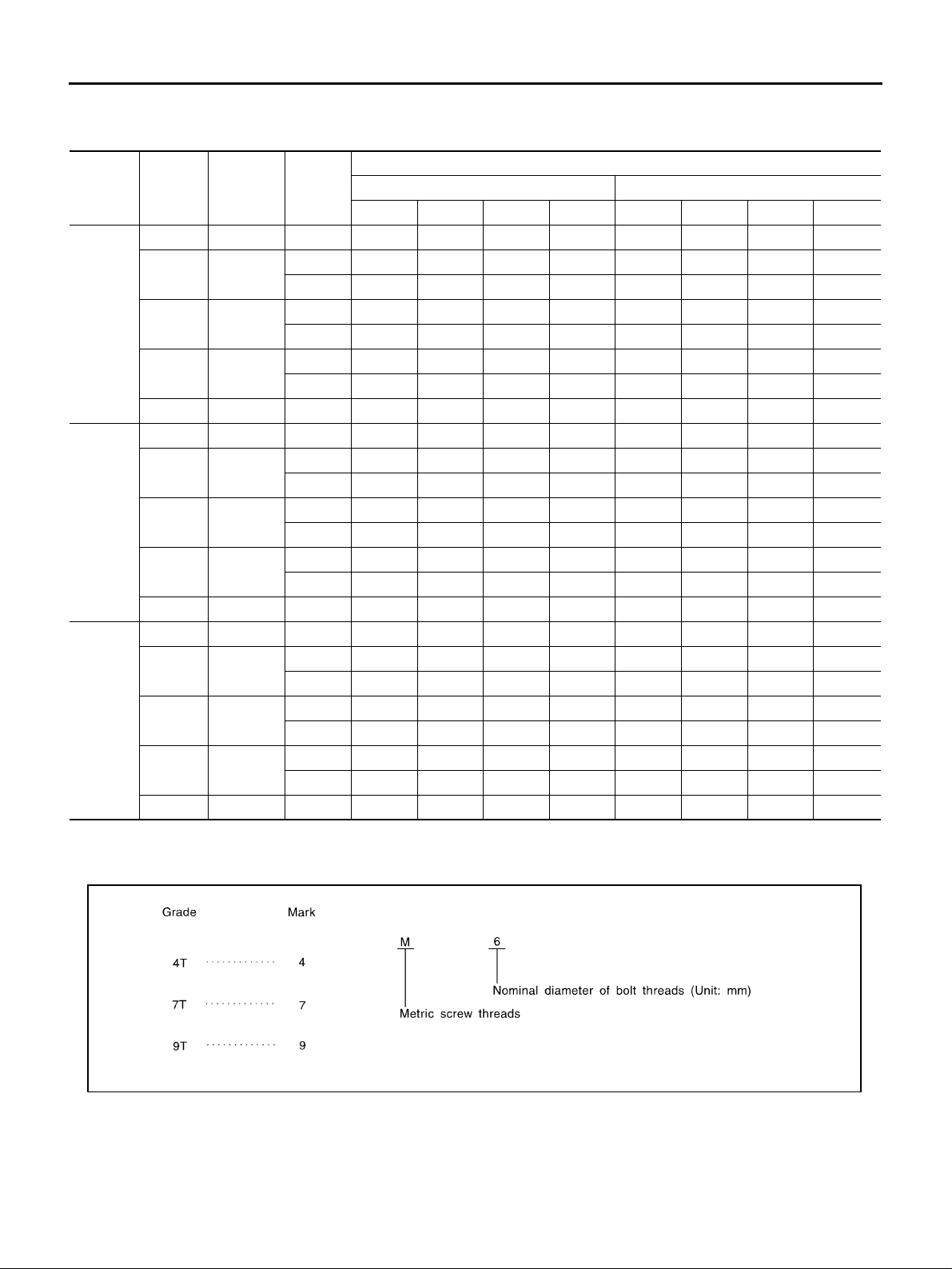
TIGHTENING TORQUE OF STANDARD BOLTS
TIGHTENING TORQUE OF STANDARD BOLTS
PFP:00000
Tightening Torque Table AAS00016
Bolt diam-
Grade Bolt size
M6 6.0 1.0 5.5 0.56 4 49 7 0.71 5 62
M8 8.0
4T
7T
9T
*: Nominal diameter
1. Special parts are excluded.
2. This standard is applicable to bolts having the following marks embossed on the bolt head.
M10 10.0
M12 12.0
M14 14.0 1.5 80 8.2 59 — 100 10 74 —
M6 6.0 1.0 9 0.92 7 80 11 1.1 8 97
M8 8.0
M10 10.0
M12 12.0
M14 14.0 1.5 130 13 96 — 170 17 125 —
M6 6.0 1.0 11 1.1 8 — 13.5 1.4 10 —
M8 8.0
M10 10.0
M12 12.0
M14 14.0 1.5 170 17 125 — 210 21 155 —
eter *
mm
Pitch
mm
N·m kg-m ft-lb in-lb N·m kg-m ft-lb in-lb
1.25 13.5 1.4 10 — 17 1.7 13 —
1.0 13.5 1.4 10 — 17 1.7 13 —
1.5 28 2.9 21 — 35 3.6 26 —
1.25 28 2.9 21 — 35 3.6 26 —
1.75 45 4.6 33 — 55 5.6 41 —
1.25 45 4.6 33 — 65 6.6 48 —
1.25 22 2.2 16 — 28 2.9 21 —
1.0 22 2.2 16 — 28 2.9 21 —
1.5 45 4.6 33 — 55 5.6 41 —
1.25 45 4.6 33 — 55 5.6 41 —
1.75 80 8.2 59 — 100 10 74 —
1.25 80 8.2 59 — 100 10 74 —
1.25 28 2.9 21 — 35 3.6 26 —
1.0 28 2.9 21 — 35 3.6 26 —
1.5 55 5.6 41 — 80 8.2 59 —
1.25 55 5.6 41 — 80 8.2 59 —
1.75 100 10 74 — 130 13 96 —
1.25 100 10 74 — 130 13 96 —
Hexagon head bolt Hexagon flange bolt
Tightening torque (Without lubricant)
GI-44
MGI044A
Page 45

RECOMMENDED CHEMICAL PRODUCTS AND SEALANTS
RECOMMENDED CHEMICAL PRODUCTS AND SEALANTS PFP:00000
Recommended Chemical Products and Sealants AAS0001C
Refer to the following chart for help in selecting the appropriate chemical product or sealant.
Product Description Purpose
Rear View Mirror
1
Adhesive
Anaerobic Liquid Gas-
2
ket
High Performance
3
Thread Sealant
4 Silicone RTV
High Temperature,
5
High Strength Thread
Locking Sealant (Red)
Medium Strength
6
Thread Locking Sealant (Blue)
Used to permanently
remount rear vie w mi rrors
to windows.
For metal-to-metal flange
sealing.
Can fill a 0.38 mm (0.015
inch) gap and provide
instant sealing for most
powertrain applications.
Provides instant sealing on
any threaded straight or
parallel threaded fitting.
(Thread sealant only, no
locking ability.)
● Do not use on plastic.
Gasket Maker
Gasket Maker for Maxima/
Quest 5-speed automatic
transmission
(RE5F22A)
Threadlocker 999MP-AM004P 999MP-AM004P
Threadlocker (service tool
removable)
Nissan North America
Part No. (USA)
999MP-AM000P 99998-50505 Permatex 81844
999MP-AM001P 99998-50503
999MP-AM002P 999MP-AM00 2P Permatex 56521
999MP-AM003P
(Ultra Grey)
––
999MP-AM005P 999MP-AM005P
Nissan Canada Part
No. (Canada)
99998-50506
(Ultra Grey)
Aftermarket Cross -
reference P art Nos.
Permatex 51813 and
51817
Permatex Ultra Grey
82194;
Three Bond
1207,1215, 1216,
1217F and 1217G;
Nissan RTV Part No.
999MP-A7007
Three Bond 1281B
or exact equivalent
in its quality
Permatex 27200;
Three Bond 1360,
1360N, 1305 N&P,
1307N, 1335,
1335B, 1363B,
1377C, 1386B, D&E
and 1388
Permatex 24200,
24206, 24240,
24283 and 09178;
Three Bond 1322,
1322N, 1324 D&N,
1333D, 1361C,
1364D, 1370C and
1374
GI
B
C
D
E
F
G
H
I
J
K
L
M
GI-45
Page 46
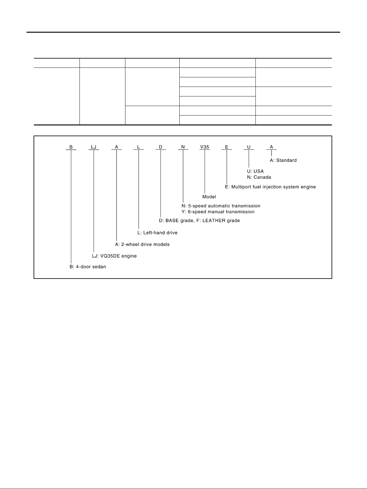
IDENTIFICATION INFORMATION
IDENTIFICATION INFORMATIO N
PFP:00010
Model Variation AAS00017
Body Engine Transmission Model Destination
Sedan VQ35DE
Prefix and suffix desi gn ati ons:
RE5R05A(5 A/T)
FS6R31A (6M/T)
BLJALDN V35 EUA
BLJALFN V35 EUA
BJLALDN V35 ENA
BLJALFN V35 ENA
BLJALFY V35 EUA USA
BLJALFY V35 ENA Canada
USA
Canada
PAIA0112E
GI-46
Page 47
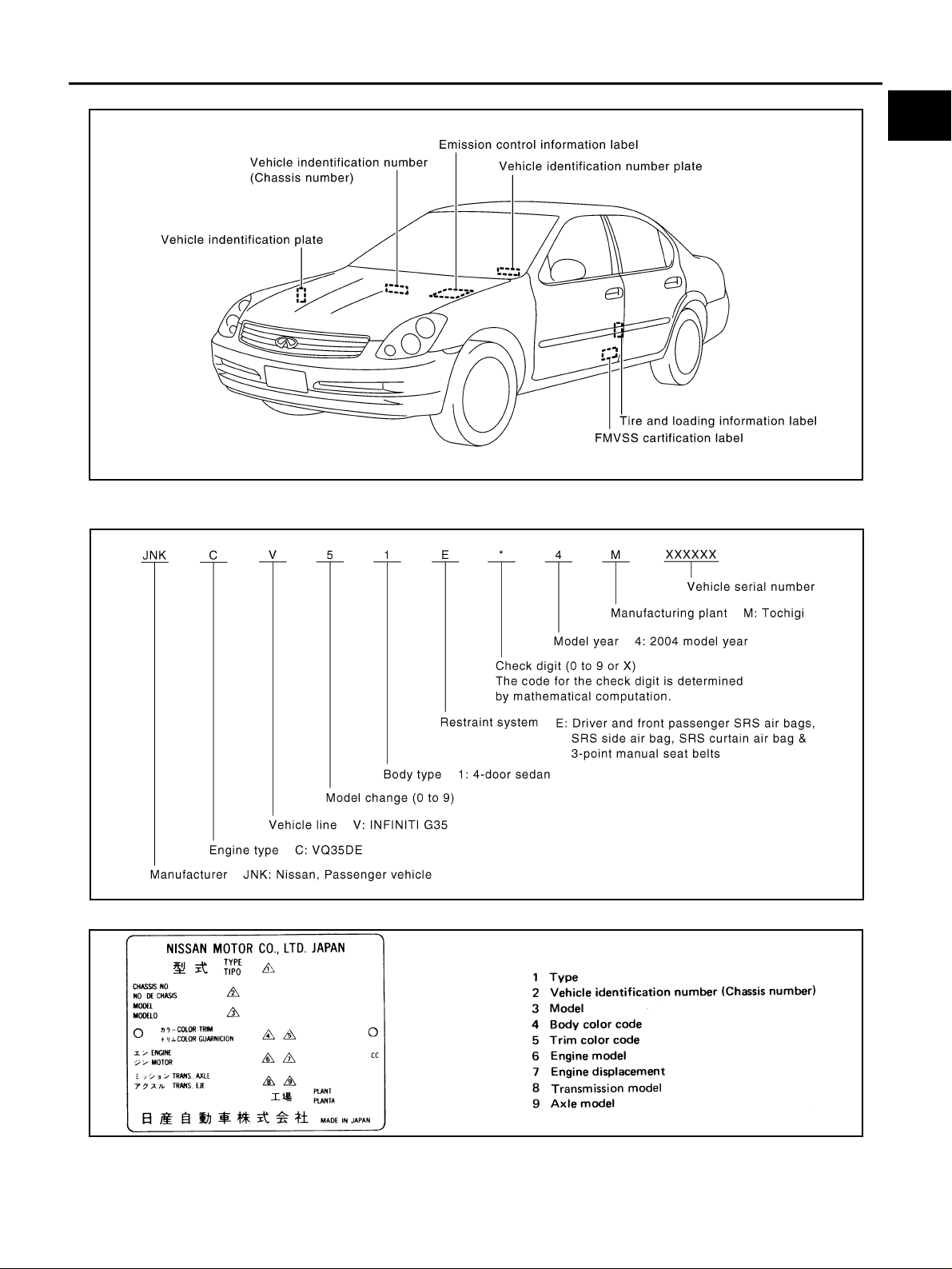
IDENTIFICATION NUMBER
IDENTIFICATION INFORMATION
GI
B
C
D
E
F
PAIA0261E
VEHICLE Identification Number ARRANGEMENT
IDENTIFICATION PLATE
PAIA0269E
G
H
I
J
K
L
M
GI-47
SGI315
Page 48
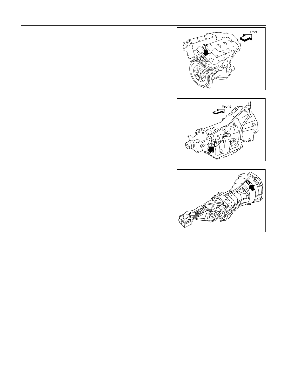
IDENTIFICATION INFORMATION
ENGINE SERIAL NUMBER
AUTOMATIC TRANSMISSION NUMBER
PAIA0051E
MANUAL TRANSMISSION NUMBER
PAIA0054E
PAIA0068E
GI-48
Page 49

IDENTIFICATION INFORMATION
Dimensions AAS00018
Unit: mm (in)
Overall length 4,736 (186.5)
Overall width 1,753 (69.0)
Overall height 1,467 (57.7)
Front tread 1,510 (59.4)*1, 1,500 (59.1)*2
Rear tread 1,515 (59.6)*1, 1,505 (59.3)*2
Wheelbase 2, 850 ( 112.2)
*1: For models with road wheel size - 16 X 6.5JJ (offset 1.57 in (40 mm))
*2: For models with aluminum wheel size - 17 X 7JJ (offset 1.75 in (45 mm ) )
Wheels & Tires AAS00019
Type Size Offset in (mm)
Road wheel Aluminum 17 X 7 JJ 1.75 (45)
Conventional P215/55R17 93V/W
Tire
*:Option
Spare
T145/90D16
Conventional*
GI
B
C
D
E
F
G
H
K
M
I
J
L
GI-49
Page 50

TERMINOLOGY
TERMINOLOGY
PFP:00011
SAE J1930 Terminology List AAS 0001A
All emission rela ted te rms u sed in th is pu blic ation in ac cordan ce with SAE J1 930 a re list ed. Ac cordi ngly, new
terms, new acronyms/abbreviations and old terms are listed in the following chart.
NEW TERM
Air cleaner ACL Air cleaner
Barometric pressure BARO ***
Barometric pressure sensor-BCDD BAROS-BCDD BCDD
Camshaft position CMP ***
Camshaft position sensor CMPS Crank angle sensor
Canister *** Canister
Carburetor CARB Carburetor
Charge air cooler CAC Intercooler
Closed loop CL Closed loop
Closed throttle position switch CTP switch Idle switch
Clutch pedal position switch CPP switch Clutch switch
Continuous fuel injection system CFI system ***
Continuous trap oxidizer system CTOX system ***
Crankshaft position CKP ***
Crankshaft position sensor CKPS ** *
Data link connector DLC * **
Data link connector for CONSULT-II DLC for CONSULT-II Diagnostic connector for CONSULT-II
Diagnostic test mode DTM Diagnostic mode
Diagnostic test mode selector DTM selector Diagnostic mode selector
Diagnostic test mode I DTM I Mode I
Diagnostic test mode II DTM II Mo de II
Diagnostic trouble code DTC Malfunction code
Direct fuel injection system DFI system ***
Distributor ignition system DI system Ignition timing control
Early fuel evaporation-mixture heater EFE-mixture heater Mixture heater
Early fuel evaporation system EFE system Mixture heater control
Electrically erasable programmable read
only memory
Electronic ignition system EI system Ignition timing control
Engine control EC ***
Engine control module ECM ECCS control unit
Engine coolant temperature ECT Engine temperature
Engine coolant temperature sensor ECTS Engine temperature sensor
Engine modification EM ***
Engine speed RPM Engine speed
Erasable programmable read only memory EPROM ***
Evaporative emission canister EVAP canister Canister
Evaporative emission system EVAP system Canister control solenoid valve
Exhaust gas recirculation valve EGR val ve EG R valv e
EEPROM ***
NEW ACRONYM /
ABBREVIATION
OLD TERM
GI-50
Page 51

TERMINOLOGY
NEW TERM
Exhaust gas recirculation control-BPT
valve
Exhaust gas recirculation control-sol enoi d
valve
Exhaust gas recirculation temperature sensor
EGR temperature sensor
Flash electrically erasable programmable
read only memory
Flash erasable programmable read only
memory
Flexible fuel sensor FFS ***
Flexible fuel system FF system ***
Fuel pressure regulator *** Pressure regulator
Fuel pressure regulator control solenoid
valve
Fuel trim FT ***
Heated Oxygen sensor HO2S Exh aust gas sensor
Idle air control system IAC system Idle speed control
Idle air control valve-air regulator IACV-air regulator Air regulator
Idle air control valve-auxiliary air contro l
valve
Idle air control valve-FICD solenoid valve IACV-FICD solenoid valve FICD solenoid valve
Idle air control valve-idle up control sole -
noid valve
Idle speed control-FI pot ISC-FI pot FI pot
Idle speed control system ISC system ***
Ignition control IC ***
Ignition control module ICM ***
Indirect fuel injection system IFI system ***
Intake air IA Air
Intake air temperature sensor IAT sensor Air temperature sensor
Knock *** Detonation
Knock sensor KS D et onation sensor
Malfunction indicator lamp MIL Check engine light
Manifold absolute pressure MAP ***
Manifold absolute pressure sensor MAPS ***
Manifold differe nt ia l pr e ssu re MDP ***
Manifold differential pressure sensor MDPS ***
Manifold surface temperature MST ***
Manifold surface temperature sensor MSTS ***
Manifold vacuum zone MVZ ***
Manifold vacuum zone sensor MVZS ** *
Mass air flow sensor MAFS Air flow meter
Mixture control solenoid valve MC solenoid valve Air-fuel ratio control solenoid valve
Multipo rt fuel injec tion Syste m MFI system Fuel injectio n c o n trol
EGRC-BPT valve BPT valve
EGRC-solenoid valve EGR contro l so lenoi d valve
EGRT sensor Exhaust gas temperature se nsor
FEEPROM ***
FEPROM ***
*** PRVR control solenoid valve
IACV-AAC valv e Auxiliary air control (AAC) valve
IACV-idle up control solenoid valve Idle up control solenoid valve
NEW ACRONYM /
ABBREVIATION
OLD TERM
GI
B
C
D
E
F
G
H
I
J
K
L
M
GI-51
Page 52

TERMINOLOGY
NEW TERM
Nonvolatile random access memory NVRAM ***
On board diagnostic system OBD system Self-diagnosis
Open loop OL Open loop
Oxidation catalyst OC Catalyst
Oxidation catalytic converter sys te m OC system ***
Oxygen sensor O2S Exhaust gas sensor
Park position switch *** Park switch
Park/neutral position switch PNP switch
Periodic trap oxidizer system PTOX system ***
Positive crankcase ventilation PCV Positive crankcase ventilation
Positive crankcase ventilation valve PCV valve PCV valve
Powertrain control module PCM ***
Programmable read only memory PROM ***
Pulsed secondary air injection control sole-
noid valve
Pulsed secondary air injection system PAIR system Air induction valve (AIV) control
Pulsed secondary air injection valve PAIR valve Air induction valve
Random access memory RAM ***
Read only memory ROM ***
Scan tool ST ***
Secondary air injection pump AIR pump ***
Secondary air injection system AIR system ***
Sequential multiport fuel injection system SFI system Sequential fuel injecti on
Service reminder indicator SRI ***
Simultaneous multiport fuel injection sys-
tem
Smoke puff lim iter system SPL system ***
Supercharger SC ***
Supercharger bypass SCB ***
System readiness test SRT ***
Thermal vacuum valve TVV Thermal vacuum valve
Three way catalyst TWC Catalyst
Three way catalytic converter system TW C syst em ***
Three way + oxidation catalyst TW C + OC Catalyst
Three way + oxidation catalytic converter
system
Throttle body TB
Throttle body fuel injection system TBI system Fuel injection control
Throttle position TP Throttle position
Throttle position sensor TPS Throttle sensor
Throttle position switch TP switch Throttle switch
Torque converter clutch solenoid valve TCC solenoid valve
PAIRC solenoid valve AIV co ntrol sol enoi d val ve
*** Simultaneous fuel injection
TWC + OC system ***
NEW ACRONYM /
ABBREVIATION
Park/neutral switch
Inhibitor switch
Neutral position switch
Throttle chamber
SPI body
Lock-up cancel solenoid
Lock-up solenoid
OLD TERM
GI-52
Page 53
TERMINOLOGY
NEW TERM
Transmission control module TCM A/T control unit
Turbocharger TC Turbocharger
Vehicle speed sensor VSS Vehicle speed sensor
Volume air flow sensor VAFS Air flow meter
Warm up oxidation catalyst WU-OC Catalyst
Warm up oxidation catalytic converter sys-
tem
Warm up three way cata ly st WU-TWC Catalyst
Warm up three way catalytic converter sys-
tem
Wide open throttle position switch WOTP switch Full switch
***: Not applicable
WU-OC system ***
WU-TWC system ***
NEW ACRONYM /
ABBREVIATION
OLD TERM
GI
B
C
D
E
F
G
H
K
M
I
J
L
GI-53
Page 54

TERMINOLOGY
GI-54
 Loading...