

Page 1
MCC
A
FST8060
Micro Commercial Corp.
21201 Itasca St.
Chatsworth, CA 91311
Phone: (818) 701-4933
Fax: (818) 701-4939
Features
• Metal of siliconrectifier, majonty carrier conducton
• Guard ring for transient protection
• Low power loss high efficiency
• High surge capacity, High current capability
Maximum Ratings
• Operating Temperature: -40°C to +150°C
• Storage Temperature: -40°C to +150°C
Maximum
MCC
Part Number
FST8060 60V 42V 60V
FST8080 80V 56V 80V
FST80100 100V 70V 100V
Recurrent
Peak Reverse
Voltage
Maximum
RMS Voltage
Maximum DC
Blocking
Voltage
THRU
FST80100
80 Amp
Schottky Barrier
Rectifier
60 to 100 Volts
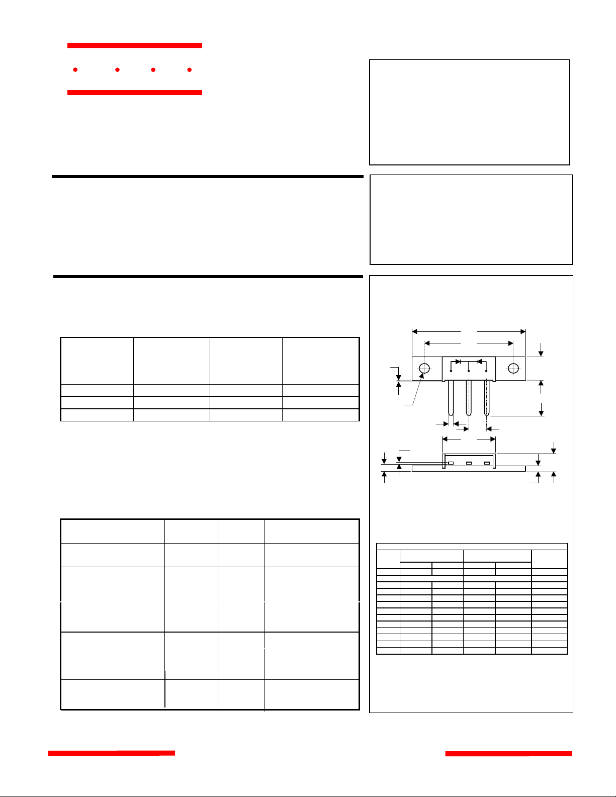
MINIMOD
F
P
N
M
K
C
B
G
E
L
J
Electrical Characteristics @ 25°C Unless Otherwise Specified
Average Forward
Current
Peak Forward Surge
Current
Maximum
Instantaneous
Forward Voltage
FST8060
FST8080-80100
Maximum DC
Reverse Current At
Rated DC Blocking
Voltage
Typical Junction
Capacitance
*Pulse Test: Pulse Width 300µsec, Duty Cycle 2%
I
F(AV)
I
FSM
V
F
I
R
C
J
80 A
A = 110°C
T
800A 8.3ms, half sine
I
= 40.0A;
.75 V
.84 V
2 mA
50 mA
FM
= 25°C
T
A
TA = 25°C
TA = 125°C
1450pF Measured at
1.0MHz, V
=5.0V
R
www.mccsemi.com
H
DIMENSIONS
INCH
ES MM
MIN MAX MIN MAX NOTEDIM
A 1.180 1.195 29.97 30.35
B .20 0 REF 5.08 REF 2PL
C .027 .037 0.69 0.94
E .350 .370 8.89 9.40
F 1.490 1.510 37.85 38.35
G .695 .715 17.65 18.16
H .088 .098 2.24 2.49
J .240 .260 6.10 6.60
K .115 .135 2.92 3.43
L .457 .477 11.61 12.12
M .065 .085 1.65 2.16
N .151 .161 3.84 4.09
P .015 .025 0.38 0.64
∅
Page 2
FST8060 thru FST80100
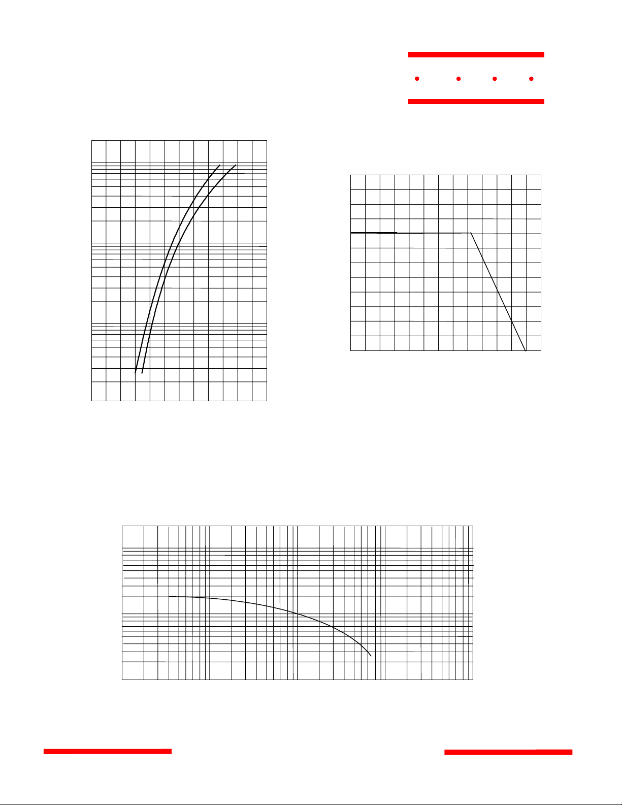
Figure 1
Typical Forward Characteristics
200
100
60
FST8060
MCC
Figure 2
Forward Derating Curve
120
Amps
40
20
10
6
4
2
1
.6
.4
.2
.1
25°C
0 0.2
Instantaneous Forward Current - Amperes
Instantaneous Forward Voltage - Volts
0.4
0.
6 0.8 1.0
Volts
FST8080-100
versus
1.2
Amps
100
80
60
40
20
Single Phase, Half Wave
60Hz Resistive or Inducti ve Load
0
150
50 70 90 110
0
C
°
Average Forward Rectified Current - Amperes
Ambient Temperature - °C
130
versus
Figure 3
Junction Capacitance
10000
6000
4000
2000
pF
1000
600
400
200
100
.1 .2 1.4 2 10 20
T
=25°C
J
400 1000
200
Volts
Junction Capacitance - pF
Reverse Voltage - Volts
404 100
versus
www.mccsemi.com
Page 3

FST8060 thru FST80100
Figure 4
Typical Reverse Characterist i cs
100
60
40
MCC
Figure 5
Peak Forward Surge Current
1000
800
mAmps
20
10
6
4
2
1.9
1.5
1.3
1.1
1.0
.6
.4
.2
.1
10
20
100
TA=125°C
= 25°C
T
A
40 60
Volts
80
120
Amps
600
400
200
100
0
1 100
2
Peak Forward Surge Current - Amperes
Number Of Cycles At 60Hz - Cycles
6
4
10 20
8
Cycles
40
60
versus
80
Instantaneous Reverse Leakage Current - MicroAmperes
Percent Of Rated Peak Reverse Voltage - Volts
www.mccsemi.com
versus
 Loading...