

Page 1
INSTRUCTION MANUAL
FRC
TEMPERATURE TRANSMITTER
(HART communication, intrinsically safe/flameproof)
■ POWER INPUT RATING
BEFORE USE ....
Thank you very much for your purchase of the Fuji FRC
Transmitter. Before use, please check contents of the package you received as outlined below.
If you have any problems or questions with the product,
please contact Fuji's Sales Office or representatives.
■ PACKAGE INCLUDES:
Transmitter .................................................................(1)
Short bar ..................................................................... (1)
Outdoor enclosure (FRC1) .......................................... (1)
Mounting screws (FRC1) ............................................(4)
2-inch pipe mounting bracket (FRC1) ................. (1) set
■ MODEL NO.
Check that model No. described on the specification label is
exactly what you ordered.
■ SAFETY PRECAUTIONS
This manual describes necessary points of caution when you
use this product, including installation, connection and basic
maintenance procedures.
Information that potentially raises safety issues is indicated
by a warning symbol (
messages before performing an operation preceded by this
symbol.
). Please refer to the following safety
POINTS OF CAUTION
The following are general precautions when using this unit.
The safety features and precautions specific to the hazardous
locations are explained in Page 10.
• Use a stable power source. The FRC restarts with a power
interruption for longer than 1 millisecond.
■ ENVIRONMENT
• The model FRC0 is for indoor use.
• When heavy dust or metal particles are present in the air,
install the unit inside an outdoor enclosure.
• Environmental (non-hazardous location) temperature must
be within -40 to +85°C (-40 to 185°F) in order to ensure
adequate life span and operation.
• For installing the FRC0 in an environment with a high
relative humidity exceeding 0 to 95% RH or in a condensing
atmosphere, install the unit inside an outdoor enclosure.
• Do not install the unit where it is subjected to continuous
vibration. Do not subject the unit to physical impact.
• For use in a hazardous location, be sure that the environmental temperature is within the temperature class required
for the area.
■ WIRING
• Do not install cables (input and output) close to noise
sources (relay drive cable, high frequency line, etc.).
• Do not bind the unit's cables together with cables where
high noise levels are present. Do not install them in the same
duct.
■ AND ....
• The unit is designed to function as soon as power is
supplied, however, a warm up for 10 minutes is required for
satisfying complete performance described in the data sheet.
MODEL
FRC
COMPONENT IDENTIFICATION
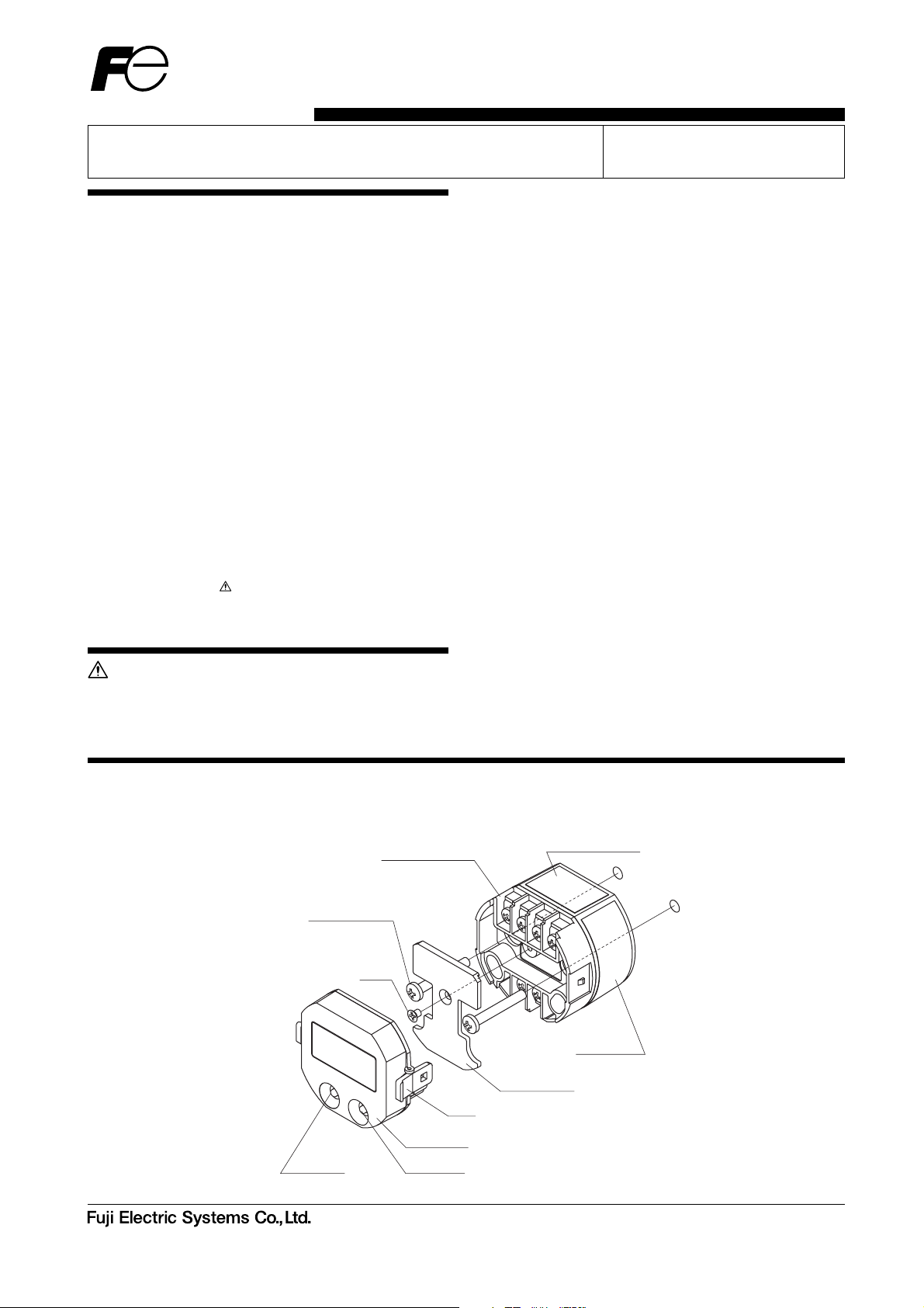
Figure 1. FRC0 exploded view and component identification
Transmitter Module
Mounting Screws
(Not Included)
Screw
LCD Module
NEXT Key
Head Office
Gate City Ohsaki, East Tower, 11-2, Osaki 1-chome,
Shinagawa-ku, Tokyo 141-0032, Japan
http://www.fesys.co.jp/eng
ENTER Key
Sales Div.
International Sales Dept.
No.1, Fuji-machi, Hino-city, Tokyo 191-8502, Japan
Phone: 81-42-585-6201, 6202 Fax: 81-42-585-6187 http://www.fic-net.jp/eng
Specification Label
Safety Label
Terminal Cover
Lever
TNFRCA-EP. 1 / 8
Page 2
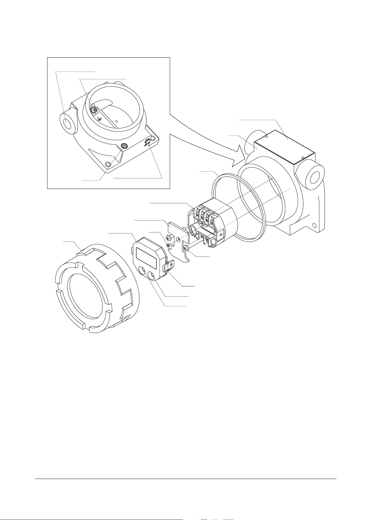
Figure 2. FRC1 exploded view component identification
• Case Details
Cable Entry Conduit
Internal Earthing Screw
Fastener
(ATEX flameproof)
External Earthing Screw
Transmitter Module
FRC
Specification Label
Case
Gasket
Cover
LCD Module
Terminal Cover
Screw
Screw
Lever
ENTER Key
NEXT Key
TNFRCA-EP. 2 / 8
Page 3
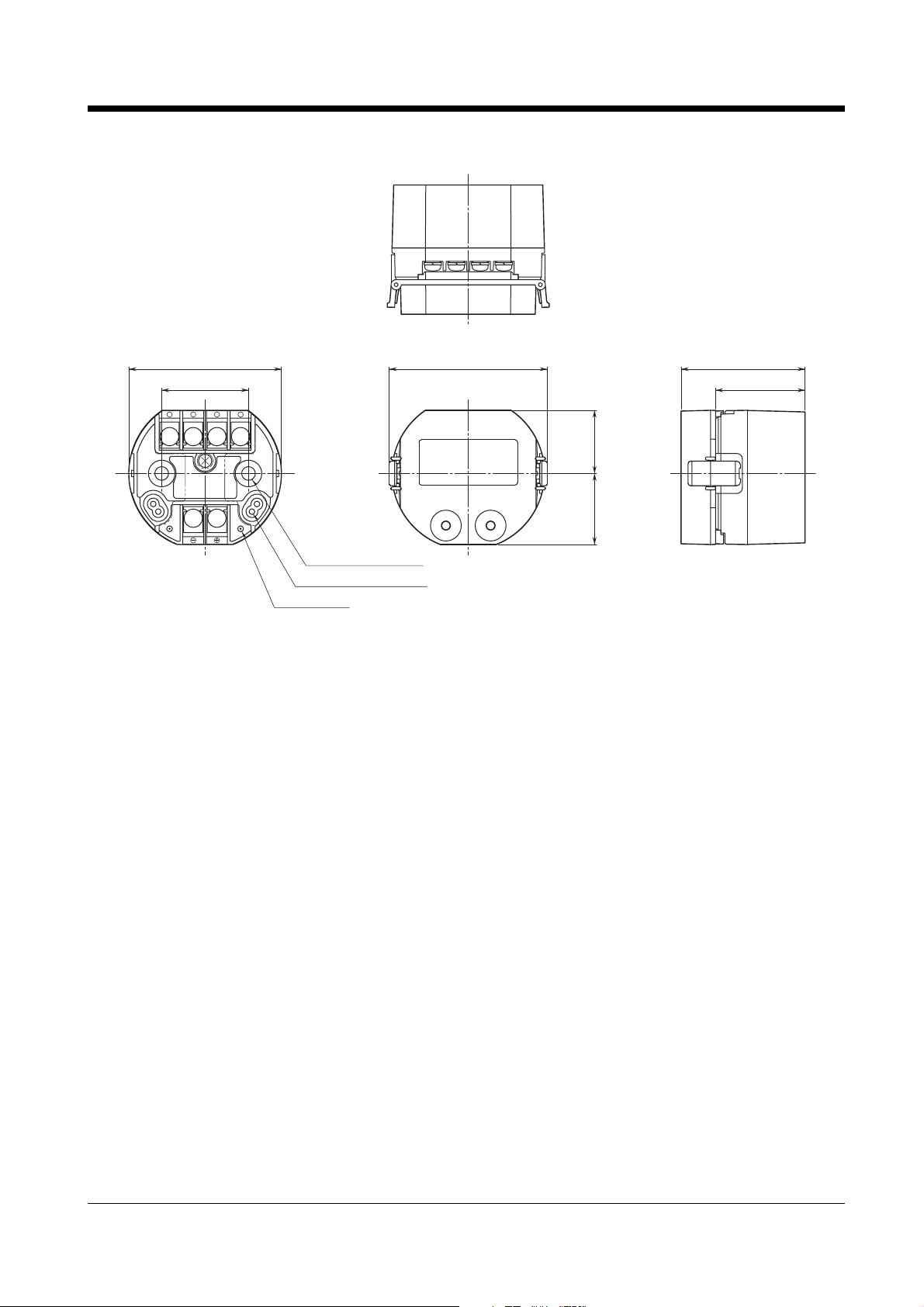
EXTERNAL DIMENSIONS mm (inch)
Figure 3. FRC0 external dimensions
FRC
59 (2.32) dia.
33 (1.30)
3214
123
–
Without LCD Module
(Terminal Assignments)
4
+
2–5 (.197) dia. MTG HOLE
24.5 (.965) deep
LCD MODULE CONNECTOR
HHC TERMINAL
63 (2.48) max.
With LCD Module
48 (1.89)
34.5 (1.36)
24.5 (.96)
27.5 (1.08)
TNFRCA-EP. 3 / 8
Page 4
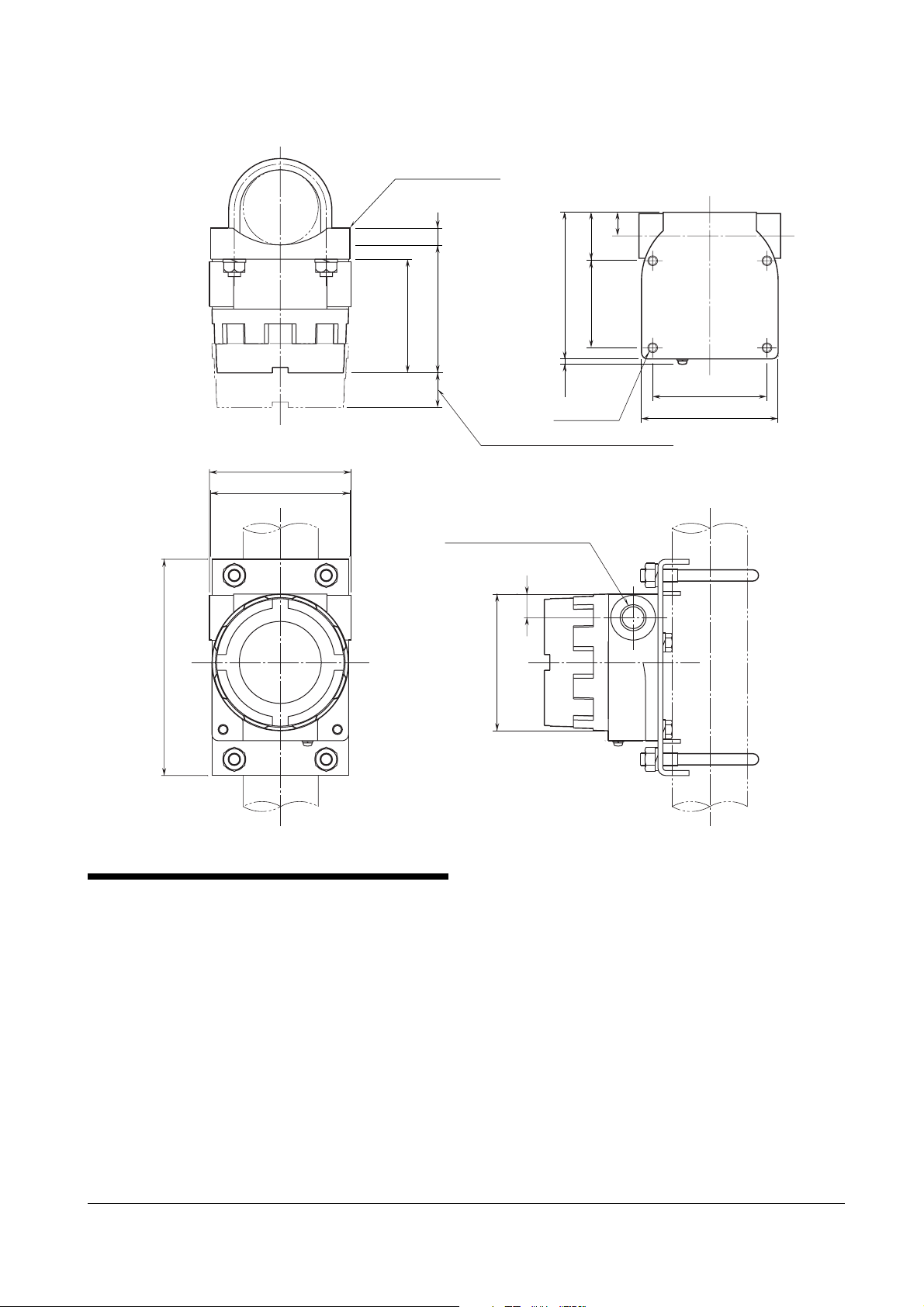
Figure 4. FRC1 external dimensions
FRC
MOUNTING BRACKET
(optional)
174 (6.85)
114 (4.49)
110 (4.33)
14
(.55)
104 (4.09)
91.5 (3.60)
26
(1.02)
SPACE REQUIRED TO REMOVE COVER
2–1/2NPT or M20x1.5 or PG13.5
19 (.75)
110 (4.33) dia.
39 (1.54)
118 (4.65)
70 (2.76)
max.
7 (.28)
4–M8, 12 deep
19 (.75)
92 (3.62)
110 (4.33)
INSTALLATION
■ LCD MODULE
• For attaching the LCD module, hold the levers at the side
and push into the connectors on top of the transmitter
module.
• When removing the module, hold the levers in the same
manner and pull.
■ WALL MOUNTING
Refer to Figures 1 and 3.
■ OUTDOOR INSTALLATION
For mounting the transmitter module inside the outdoor
enclosure, refer to Figure 2.
TNFRCA-EP. 4 / 8
Page 5
FRC
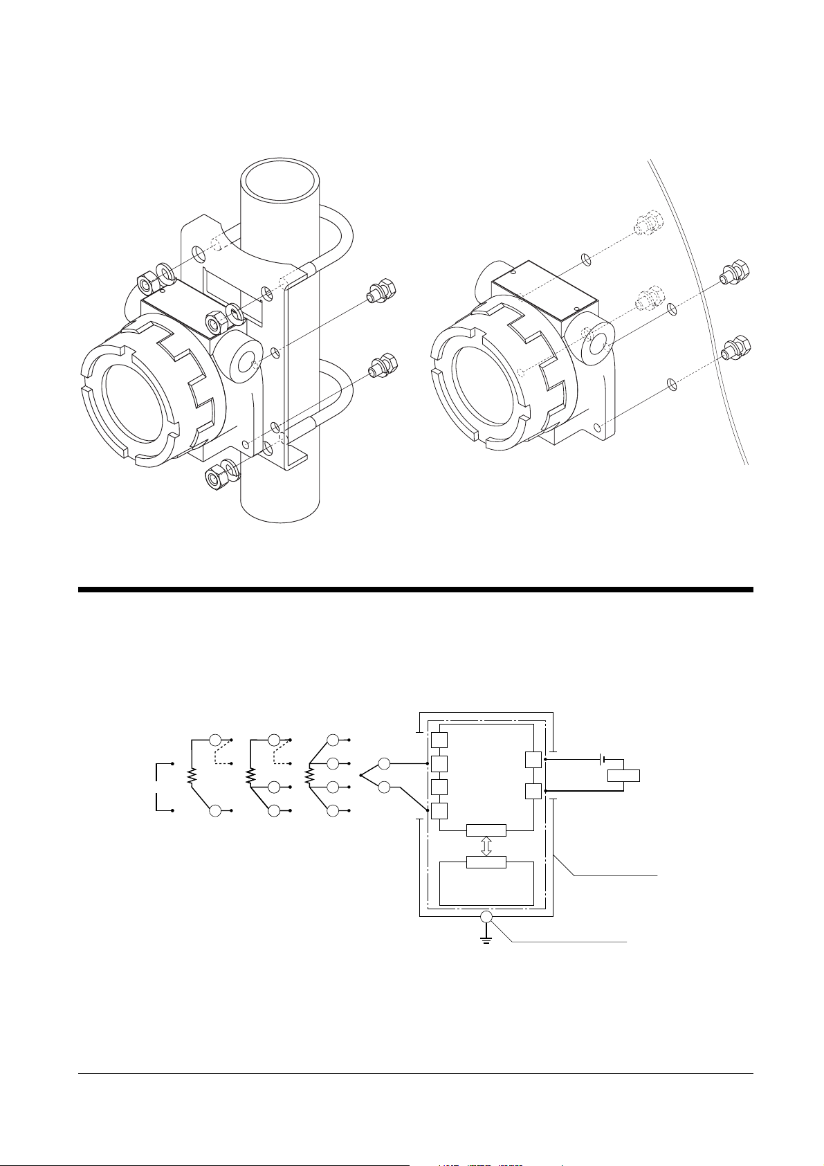
■ MOUNTING THE ENCLOSURE ON A PIPE
See Figures 5 below.
Figure 5. Pipe mounting
■ MOUNTING THE ENCLOSURE ON A WALL
See Figures 4 and 6 (below).
Figure 6. Wall mounting
TERMINAL CONNECTIONS
Connect the unit as in the diagram below. For use in a hazardous location, refer to "Installation Diagram" attached at the end
of this manual.
Figure 7. Connection diagram
RTD
T/C4-wire3-wire2-wireDC mV
A
A
+
–
1
*
B
*1. Close across the terminals 1 & 2.
A
1
*
B
B
B
B
A
A
B
B
+
–
+
–
1
2
3
4
Transmitter
Module
Connector
LCD Module
(optional)
+
24VDC
OUTPUT
–
4 – 20mADC
*2. Limited to 250 – 1100Ω for
HART communication.
External Earthing Terminal
LOAD
Outdoor Enclosure
2
*
TNFRCA-EP. 5 / 8
Page 6

CHECKING
Warning! Whenever you need to measure voltage across
the terminals or apply a simulated input signal to the terminals, make sure that there is no danger of explosion in the
atmosphere.
1) Terminal wiring: Check that all cables are correctly
connected according to the connection diagram.
2) Input type and range setting: Check that the input type
and range are correctly set.
3) Input: Check that the input signal is within 0 – 100% of
the full-scale.
If the thermocouple/RTD or its extension wires are bro-
ken, the output goes over 100% (below 0% with downscale)
due to the burnout function. Check leadwires in such a
case.
4) Output: Check that the load is within the permissible
limit including wiring resistance.
Load Resistance (Ω) =
Supply Voltage (V) –␣ 12 (V)
0.024 (A)
(including leadwire resistance)
ADJUSTMENT PROCEDURE
■ USING THE HART COMMUNICATION
Refer to the HART Setup Manual (EM-7451-FIC-B). For
operating an HHC (Hand-Held Communicator), refer to its
instruction manual.
■ USING THE LCD MODULE
Figure 8 shows the display panel configuration of the LCD
module, and Figure 9 shows the basic operation flow chart for
programming the transmitter.
• How to Input Numerical Figures on the LCD
Numerical figures (numbers) can be set by combining NEXT
and ENTER key operations.
Pressing the NEXT key increases the value from 0 to 9 and
back to 0 again. Pressing the ENTER key when a desired
value is shown sets the value and then moves to the next less
significant digit. Pressing the ENTER key at the least
significant digit completes the input.
For the most significant digit, numbers change from 0, 1, 2
through 9, then -0, -1, -2, through -9, and then back to 0.
• Basic Operation
When the power supply is turned on, the "RUN" indicator on
the LCD module flashes until communication with the transmitter module is established. Once established, the "RUN"
indicator remains on.
The LCD starts up in the Display Mode.
The upper (first) row on the display indicates numerical
figures, and the lower (second) row indicates messages.
Pressing the NEXT key one or more times switches the
module between the Configuration Mode, Calibration Mode
and Display Mode.
Pressing the ENTER key in the Configuration Mode or
Calibration Mode calls up the first programming item (step).
In this state, every time the NEXT key is pressed, the next
item and current setting is displayed until it returns to the
Display Mode after the last programming item.
FRC
Whenever the type/value within a particular programming
step can be changed, "PGM" is shown on the LCD. When each
step is complete, the "PGM" indicator is turned off.
• LCD Panel Indication in the Display Mode
"Burnout State" includes not only a temperature sensor's
wire breakdown but also an overrange input outside the
physically set range for thermocouples or RTDs.
"Saturation State" is when an overrange input is applied
outside the physically set range and proportional to the
output smaller than 3.8mA or exceeding 21.6mA.
Normal State
Top row Numerical figures
Bottom row HART address*
BO OFF
ERR OFF
asterisk OFF
Eng. unit ON*
1
Saturation State
Top row Numerical figures
Bottom row HART address*
BO OFF
ERR OFF
asterisk ON
Eng. unit ON*
1
Burnout State
Top row Blank
Bottom row HART address*
BO ON
ERR OFF
asterisk ON
Eng. unit ON*
1
*1. When an appropriate unit symbol is not available
among the selections on the LCD, the bottom row indicates
the unit and HART address alternately.
• Programming Procedure in the Configuration Mode
1) Input Type (SelectInput)
First choose the input type. Pressing the NEXT key one or
more times switches between each of the available input
types. Press ENTER to set a desired input type.
When Thermocouple, RTD or potentiometer is selected,
the display goes to the sensor type list. Use the NEXT and
ENTER keys to choose a sensor type.
See Table 1 through 3 for available input types.
Table 1. Input types
Input type LCD bottom row
Thermocouple TC
2-wire RTD 2-RTD
3-wire RTD 3-RTD
4-wire RTD 4-RTD
mV MV
1
1
1
TNFRCA-EP. 6 / 8
Page 7

FRC
Table 2. Thermocouples
Sensor type Bottom row Sensor type Bottom row
B TC/B T TC/T
E TC/E W TC/W5
J TC/J U TC/U
K TC/K L TC/L
N TC/N P TC/P
R TC/R PR TC/PR
S TC/S
Table 3. RTDs
RTD type Top row Bottom row*
IEC Pt 100 100 n-IPT
*2. n = 2 : 2-wire, 3 : 3-wire, 4 : 4-wire
2) Temperature Unit (SelectUnit)
For a thermocouple or RTD input, the Temperature Unit
can be specified.
At the initial state, the LCD shows the current setting.
Pressing the NEXT key one or more times switches between the available temperature units. Stop when a
desired selection is displayed, and press ENTER.
For mV, resistance and potentiometer inputs, settings
other than "mV", "Ω" and "%" respectively cannot be
selected.
See Table 4.
Table 4. Temperature units
Temperature unit LCD bottom row
Degree Celcius DEG C
Degree Fahrenheit DEG F
Degree Rankine DEG R
Degree Kelvin DEG K
6) Display Item (SelectDisplay)
Specifies the item to be monitored on the LCD in the
Display Mode.
At the initial state, the LCD shows the current setting.
Pressing the NEXT key one or more times switches between available selection items. Stop when a desired
selection is displayed, and press ENTER.
See Table 5 for available display items.
Table 5. Display items
Item Bottom row
Input (unit as selected in SelectUnit) I ENG
2
Input in % I PER
Output in % O PER
Output in mA O ENG
Cold junction temperature (T/C only) CJM
• Programming Procedure in the Calibration Mode
1) Output Zero Adjustment (TrimOutput4mA)
Used to fine tune 4mA output.
At the initial state, the unit outputs 4mA regardless of
actual input value.
Set an actual measured value on the top row of the LCD.
2) Output Span Adjustment (TrimOutput20mA)
Used to fine tune 20mA output.
At the initial state, the unit outputs 20mA regardless of
actual input value.
Set an actual measured value on the top row of the LCD.
3) Burnout (BurnoutDirection)
At the initial state, the LCD shows the current setting.
Pressing the NEXT key one or more times switches between "High" (upscale), "Low" (downscale), and "Off" (no
burnout). Stop when a desired selection is displayed, and
press ENTER.
4) Lower Range Input (InputLowerRange)
Lower and Upper Input ranges can be specified.
At the initial state, the LCD shows the current 0%*
setting.
Values are indicated in the selected temperature unit (T/
C and RTD) or mV (DC mV).
Set an actual value on the top row of the LCD.
*For potentiometer input, enter the percentage of the total
resistance for both the lower and upper ranges.
5) Upper Range Input (InputUpperRange)
Refer to the Lower Range Input.
TNFRCA-EP. 7 / 8
Page 8
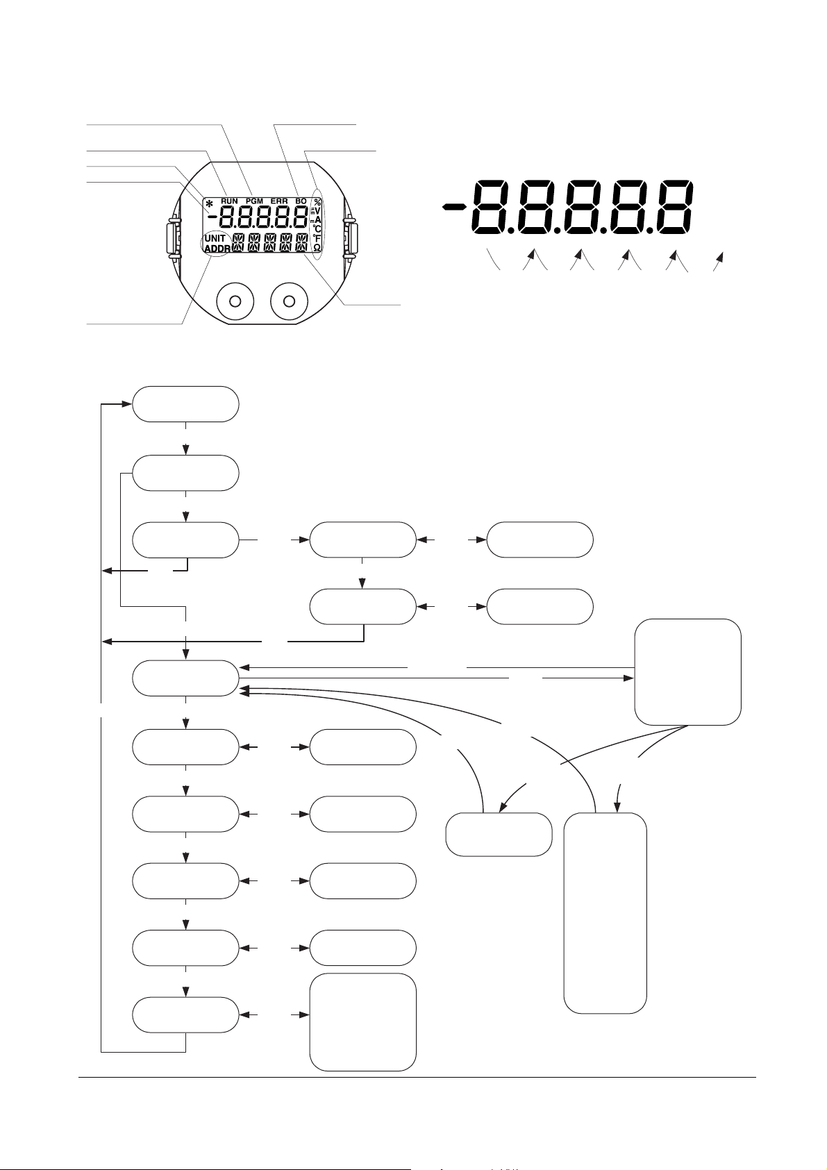
Figure 8. LCD display panel configuration
PGM: ON when programmable
RUN: Remains ON with the
communication extablished
: ON at saturation
*
Top Row (numerical)
BO: ON at burnout
FRC
Engineering Unit
Symbols
•Key Operations in Entering Numerial Value
Input Complete
NEXT ENTER
Bottom Row Contents
Unexplained symbols are unused for the B6U and B6U-B.
Figure 9. Programming operation flowchart
OperateMode
Next
CFGMode?
Next
Next
CALMode?
Next
Enter
SelectInput
Next
SelectUnit
Next
Select
BurnoutDirection
Next
InputLowerRange
Next
InputUpperRange
Next
DisplayStatus
Enter
Next
Enter
Enter
Enter
Enter
Enter
Enter Enter
Bottom Row
TrimOutput4mA
Next
TrimOutput20mA Numerical Value
NextKey
Select Unit
NextKey
Select Burnout
Numerical Value
Numerical Value
NextKey
Select Displayed Item
•Input (eng. unit)
•Input %
•Output %
•Output mA
•Cold Juction Temp
Enter
Enter
Enter (MV)
Enter
Next : Increment value (and sign for the MSD)
Numerical Value
Enter
Enter
Enter
(2-RTD
3-RTD
4-RTD)
NextKey
Select RTD
IPt 100
Enter
Enter
Enter
(TC)
NextKey
Select
Thermocouple
B
E
J
K
N
R
S
T
W
U
L
P
PR
Enter
Select Input Type
Enter
NextKey
Thermocouple
2-wire RTD
3-wire RTD
4-wire RTD
mV
TNFRCA-EP. 8 / 8
 Loading...