

Page 1
Differential Magneto Resistor FP 425 L 90
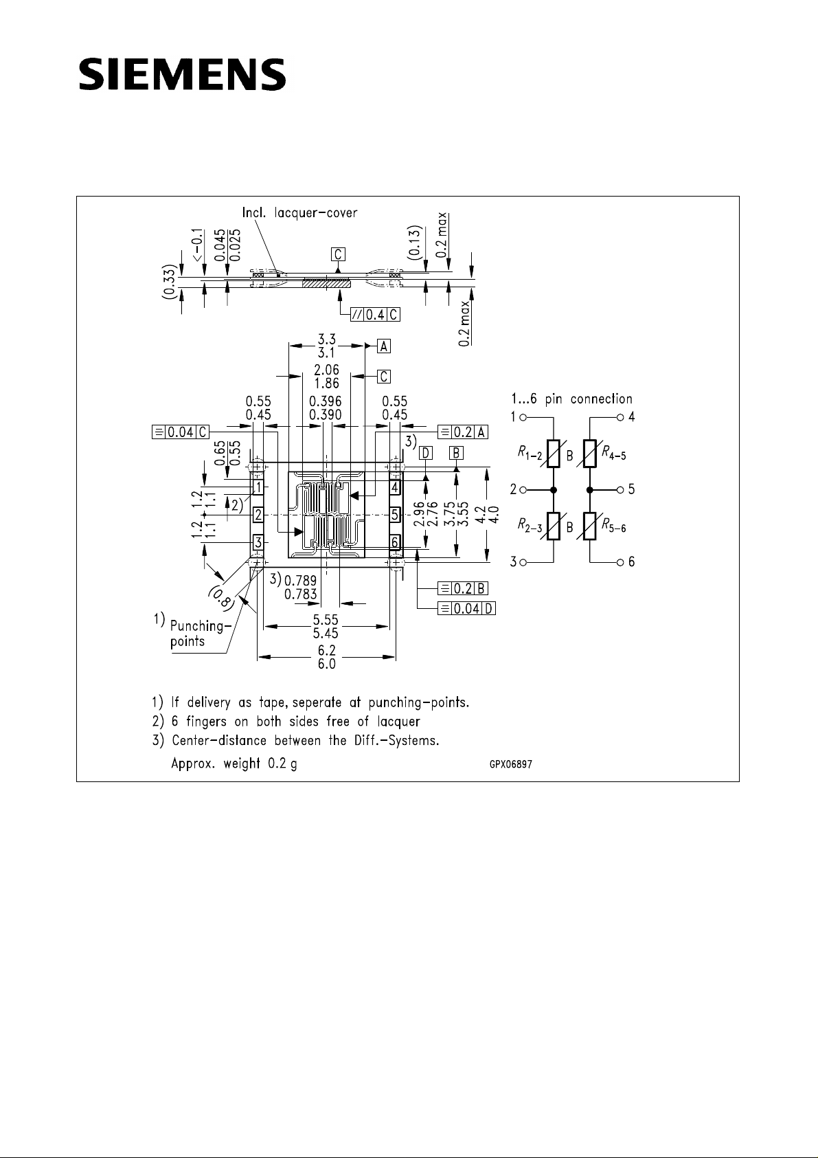
Dimensions in mm
Features
• Double differential magneto resistor on one carrier
• Accurate intercenter spacing
• High operating temperature range
• High output voltage
Typical applications
• Incremental angular encoders
• Detection of sense of rotation
• Detection of speed
• Detection of position
• Compact construction
• Available in strip form for automatic assembly
• Optimized intercenter spacing on modules
m = 0.5 mm
• Reduced temperature dependence of offset
voltage
Semiconductor Group 1 07.96
Page 2

FP 425 L 90
Type Ordering Code
FP 425 L 90 Q65425-L90 (singular)
FP 425 L 90 Q65425-L0090E001 (taped)
The double differential magneto resistor assembly consists of two pairs of magneto
resistors, (L-type InSb/NiSb semiconductor resistors whose resistance value can be
magnetically controlled), which are fixed to a silicon substrate. Contact to the magneto
resistors is achieved using a copper/polyimide carrier film known as TAB.
The basic resistance of each of the magneto resistors is 90 Ω. The two series coupled
pairs of magneto resistor are actuated by an external magnetic field or can be biased by
a permanent magnet and actuated by a soft iron target.
Semiconductor Group 2
Page 3

FP 425 L 90
Maximum ratings
Parameter Symbol Value Unit
Operating temperature
Storage temperature
Power dissipation
Supply voltage (
1)
B = 0.2 T, T
Thermal conductivity
–attached to heatsink
–in still air
T
Characteristics (
= 25 °C)
A
Nominal supply voltage (
Basic resistance
(
I < 1 mA, B = 0 T)
Center symmetry
3)
= 25 °C) V
A
B = 0.2 T)
2)
T
T
P
G
G
V
R
M
A
stg
tot
IN
thcase
thA
INN
01-3
– 40 / + 175 °C
– 40 / + 185 °C
800 mW
8V
20
2
mW/K
mW/K
5V
160 – 280 Ω
≤ 3%
Relative resistance change
(
R
= R
0
B = ± 0.3 T
01-3
, R
4)
at B = 0 T)
04-6
B = ± 1 T
Temperature coefficient
B = 0 T
B = ± 0.3 T
B = ± 1 T
1) T = T
2) T = T
3)
4) 1 T = 1 Tesla = 10
case
case
M
M
, T < 80 °C
R
--------------------------------=
R
--------------------------------=
01 2–
04 5–
R
R
–
01 2–
–
04 5–
4
R
02 3–
R
05 6–
Gauss
× 100% for R
× 100% for R
01-2
04-5
> R
> R
R
B/R0
TC
02-3
05-6
–
> 1.7
> 7
R
– 0.16
– 0.38
– 0.54
%/K
%/K
%/K
Semiconductor Group 3
Page 4

FP 425 L 90
Max. power dissipation versus
temperature
P
= f(T), T = T
tot
case
, T
A
Maximum supply voltage
versus temperature
V
= f(T), B = 0.2 T
IN
Typical MR resistance
versus temperature
R
01-3, 4-6
= f(TA), B = Parameter
Typical MR resistance
versus magnetic induction
R
01-3, 4-6
= f(B), TA = 25 °C
B
Semiconductor Group 4
 Loading...