

Page 1
Product Preview
FM25CL64
64Kb FRAM Serial 3V Memory
Features
64K bit Ferroelectric Nonvolatile RAM
• Organized as 8,192 x 8 bits
• Unlimited Read/Write Cycles
• 10 Year Data Retention
• NoDelay™ Writes
• Advanced High-Reliability Ferroelectric Process
Very Fast Serial Peripheral Interface - SPI
• Up to 20 MHz Frequency
• Direct Hardware Replacement for EEPROM
• SPI Mode 0 & 3 (CPOL, CPHA=0,0 & 1,1)
Description
The FM25CL64 is a 64-kilobit nonvolatile memory
employing an advanced ferroelectric process. A
ferroelectric random access memory or FRAM is
nonvolatile and performs reads and writes like a
RAM. It provides reliable data retention for 10 years
while eliminating the complexities, overhead, and
system level reliability problems caused by
EEPROM and other nonvolatile memories.
Unlike serial EEPROMs, the FM25CL64 performs
write operations at bus speed. No write delays are
incurred. The next bus cycle may commence
immediately without the need for data polling. The
next bus cycle may start immediately. In addition, the
product offers virtually unlimited write endurance,
orders of magnitude more endurance than EEPROM.
Also, FRAM exhibits much lower power during
writes than EEPROM since write operations do not
require an internally elevated power supply voltage
for write circuits.
These capabilities make the FM25CL64 ideal for
nonvolatile memory applications requiring frequent
or rapid writes. Examples range from data collection,
where the number of write cycles may be critical, to
demanding industrial controls where the long write
time of EEPROM can cause data loss.
The FM25CL64 provides substantial benefits to users
of serial EEPROM as a hardware drop-in
replacement. The FM25CL64 uses the high-speed
SPI bus, which enhances the high-speed write
capability of FRAM technology. Device
specifications are guaranteed over an industrial
temperature range of -40°C to +85°C.
Sophisticated Write Protection Scheme
• Hardware Protection
• Software Protection
Low Power Consumption
• Low Voltage Operation 3.0-3.65V
• 1 µA Standby Current
Industry Standard Configurat ion
• Industrial Temperature -40°C to +85°C
• 8-pin SOP
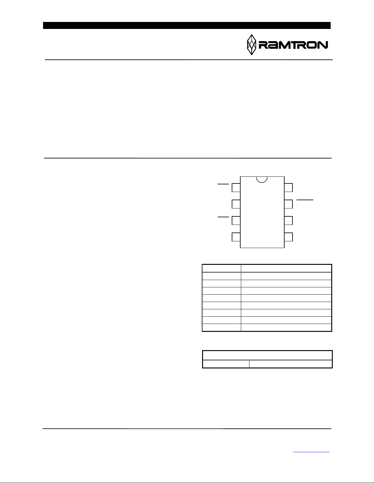
Pin Configuration
CS
SO
WP
VSS
Pin Name Function
/CS Chip Select
/WP Write Protect
/HOLD Hold
SCK Serial Clock
SI Serial Data Input
SO Serial Data Output
VDD Supply Voltage
VSS Ground
Ordering Information
FM25CL64-S 8-pin SOP
1
2
3
4
8
VDD
7
HOLD
6
SCK
5
SI
This is a product that is u nde r de v e lopment. Characteristic data and Ramtron International Corporation
and other specifications are design goals. Ramtron reserves the right 1850 Ramtron Drive, Colorado Springs, CO 80921
to change or discontinue this product without notice. (800) 545-FRAM, (719) 481-7000, Fax (719) 481-7058
www.ramtron.com
Rev. 0.3
Jan. 2002 Page 1 of 13
Page 2
FM25CL64
WP
CS
HOLD
SCK
`
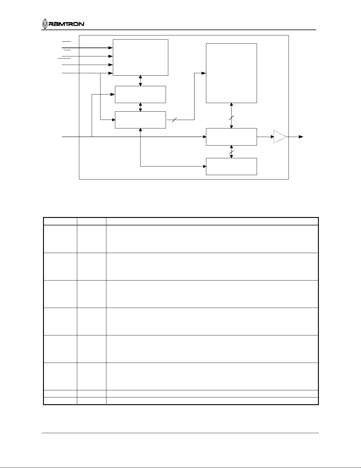
Instruction Decode
Clock Generator
Control Logic
Write Protect
Instruction Register
Address Register
Counter
13
2,048 x 32
FRAM Array
8
Data I/O Register
3
Nonvolatile Status
Register
SOSI
Figure 1. Block Diagram
Pin Descriptions
Pin Name I/O Description
/CS Input Chip Select: This active low input activates the device. When high, the device enters
low-power standby mode, ignores other inputs, and all outputs are tri-stated. When
low, the device internally activates the SCK signal. A falling edge on /CS must occur
prior to every op-code.
SCK Input Serial Clock: All I/O activity is synchronized to the serial clock. Inputs are latched on
the rising edge and outputs occur on the falling edge. Since the device is static, the
clock frequency may be any value between 0 and 20 MHz and may be interrupted at
any time.
/HOLD Input Hold: The /HOLD pin is used when the host CPU must interrupt a memory operation
for another task. When /HOLD is low, the current operation is suspended. The device
ignores any transition on SCK or /CS. All transitions on /HOLD must occur while
SCK is low.
/WP Input Write P rotect: This active low pin prevents write operations to the status register. This
is critical since other write protection features are controlled through the status
register. A complete explanation of write protection is provided below. *Note that the
function of /WP is different from the FM25040 where it prevents all writes to the part.
SI Input Serial Input: All data is input to the device on this pin. The pin is sampled on the
rising edge of SCK and is ignored at other times. It should always be driven to a valid
logic level to meet IDD specifications.
* SI may be connected to SO for a single pin data interface.
SO Output Serial Output: This is the data output pin. It is driven during a read and remains tri-
stated at all other times including when /HOLD is low. Data transitions are driven on
the falling edge of the serial clock.
* SO may be connected to SI for a single pin data interface.
VDD Supply P ower Supply (3.0V to 3.65V)
VSS Supply Ground
Rev. 0.3
Jan. 2002 Page 2 of 13
Page 3

FM25CL64
Overview
The FM25CL64 is a serial FRAM memory. The
memory array is logically organized as 8,192 x 8 and
is accessed using an industry standard Serial
Peripheral Interface or SPI bus. Functional operation
of the FRAM is similar to serial EEPROMs. The
major difference between the FM25CL64 and a serial
EEPROM with the same pinout is the FRAM’s
superior write performance.
Memory Architecture
When accessing the FM25CL64, the user addresses
8,192 locations of 8 data bits each. These data bits
are shifted serially. The addresses are accessed using
the SPI protocol, which includes a chip select (to
permit multiple devices on the bus), an op-code, and
a two-byte address. The upper 3 bits of the address
range are ‘don’t care’ values. The complete address
of 13-bits specifies each byte address uniquely.
Most functions of the FM25CL64 either are
controlled by the SPI interface or are handled
automatically by on-board circuitry. The access time
for memory operation is essentially zero, beyond the
time needed for the serial protocol. That is, the
memory is read or written at the speed of the SPI bus.
Unlike an EEPROM, it is not necessary to poll the
device for a ready condition since writes occur at bus
speed. So, by the time a new bus transaction can be
shifted into the device, a write operation will be
complete. This is explained in more detail in the
interface section.
Users expect several obvious system benefits from
the FM25CL64 due to its fast write cycle and high
endurance as compared with EEPROM. In addition
there are less obvious benefits as well. For example
in a high noise environment, the fast-write operation
is less susceptible to corruption than an EEPROM
since it is completed quickly. By contrast, an
EEPROM requiring milliseconds to write is
vulnerable to noise during much of the cycle.
Note that the FM25CL64 contains no power
management circuits other than a simple internal
power-on reset. It is the user’s responsibility to
ensure that VDD is within datasheet tolerances to
prevent incorrect operation.
Serial Peripheral Interface – SPI Bus
The FM25CL64 employs a Serial Peripheral
Interface (SPI) bus. It is specified to operate at speeds
up to 20 MHz. This high-speed serial bus provides
high performance serial communication to a host
microcontroller. Many common microcontrollers
have hardware SPI ports allowing a direct interface.
It is quite simple to emulate the port using ordinary
port pins for microcontrollers that do not. The
FM25CL64 operates in SPI Mode 0 and 3.
The SPI interface uses a total of four pins: clock,
data-in, data-out, and chip select. It is possible to
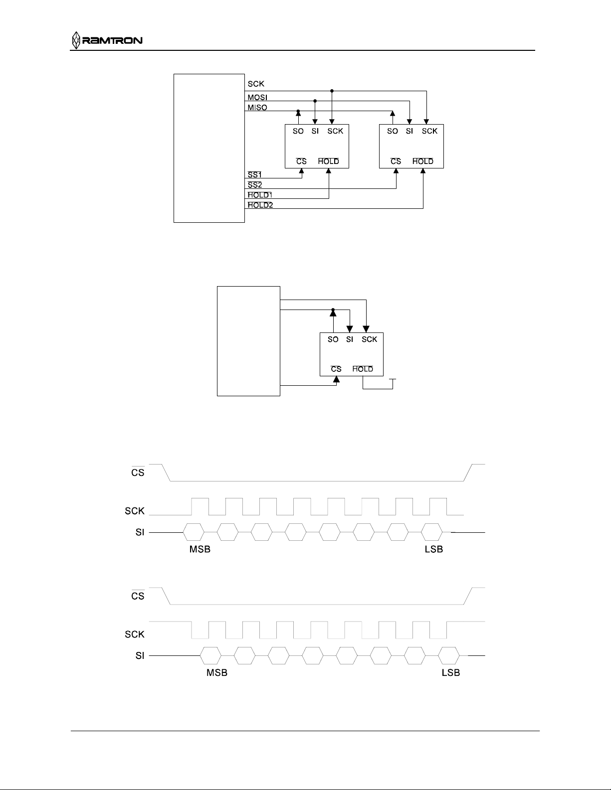
connect the two data pins together. Figure 2
illustrates a typical system configuration using the
FM25CL64 with a microcontroller that offers an SPI
port. Figure 3 shows a similar configuration for a
microcontroller that has no hardware support for the
SPI bus.
Protocol Overview
The SPI interface is a synchronous serial interface
using clock and data pins. It is intended to support
multiple devices on the bus. Each device is activated
using a chip select. Once chip select is activated by
the bus master, the FM25CL64 will begin monitoring
the clock and data lines. The relationship between the
falling edge of /CS, the clock and data is dictated by
the SPI mode. The device will make a determination
of the SPI mode on the falling edge of each chip
select. While there are four such modes, the
FM25CL64 supports modes 0 and 3. Figure 4 shows
the required signal relationships for modes 0 and 3.
For both modes, data is clocked into the FM25CL64
on the rising edge of SCK and data is expected on the
first rising edge after /CS goes active. If the clock
begins from a high state, it will fall prior to beginning
data transfer in order to create the first rising edge.
The SPI protocol is controlled by op-codes. These
op-codes specify the commands to the device. After
/CS is activated the first byte transferred from the bus
master is the op-code. Following the op-code, any
addresses and data are then transferred.
Certain op-codes are commands with no subsequent
data transfer. The /CS must go inactive after an
operation is complete and before a new op-code can
be issued. There is one valid op-code only per active
chip select.
Rev. 0.3
Jan. 2002 Page 3 of 13
Page 4
FM25CL64
Microcontroller
SPI Mode 0: CPOL=0, CPHA=0
SPI
MOSI : Master Out Slave In
MISO : Master In Slave Out
SS : Slave Select
FM25640
FM25CL64 FM25CL64
FM25640
Figure 2. System Configuration with SPI port
P1.0
P1.1
Microcontroller
FM25640
FM25CL64
P1.2
Figure 3. System Configuration without SP I port
01234567
SPI Mode 3: CPOL=1, CPHA=1
01234567
Figure 4. SPI Modes 0 & 3
Rev. 0.3
Jan. 2002 Page 4 of 13
Page 5
FM25CL64
Data Transfer
All data transfers to and from the FM25CL64 occur
in 8-bit groups. They are synchronized to the clock
signal (SCK), and they transfer most significant bit
(MSB) first. Serial inputs are registered on the rising
edge of SCK. Outputs are driven from the falling
edge of SCK.
Command Structure
There are six commands called op-codes that can be
issued by the bus master to the FM25CL64. They are
listed in the table below. These op-codes control the
functions performed by the memory. They can be
divided into three categories. First, there are
commands that have no subs equent operatio ns. They
perform a single function such as to enable a write
operation. Second are commands followed by one
byte, either in or out. They operate on the status
register. The third group includes commands for
memory transactions followed by address and one or
more bytes of data.
Table 1. Op-code Commands
Name Description Op-code
WREN
WRDI
RDSR
WRSR
READ
WRITE
Set Write Enable Latch
Write Disable
Read Status Register
Write Status Register
Read Memory Data
Write Memory Data
00000110b
00000100b
00000101b
00000001b
00000011b
00000010b
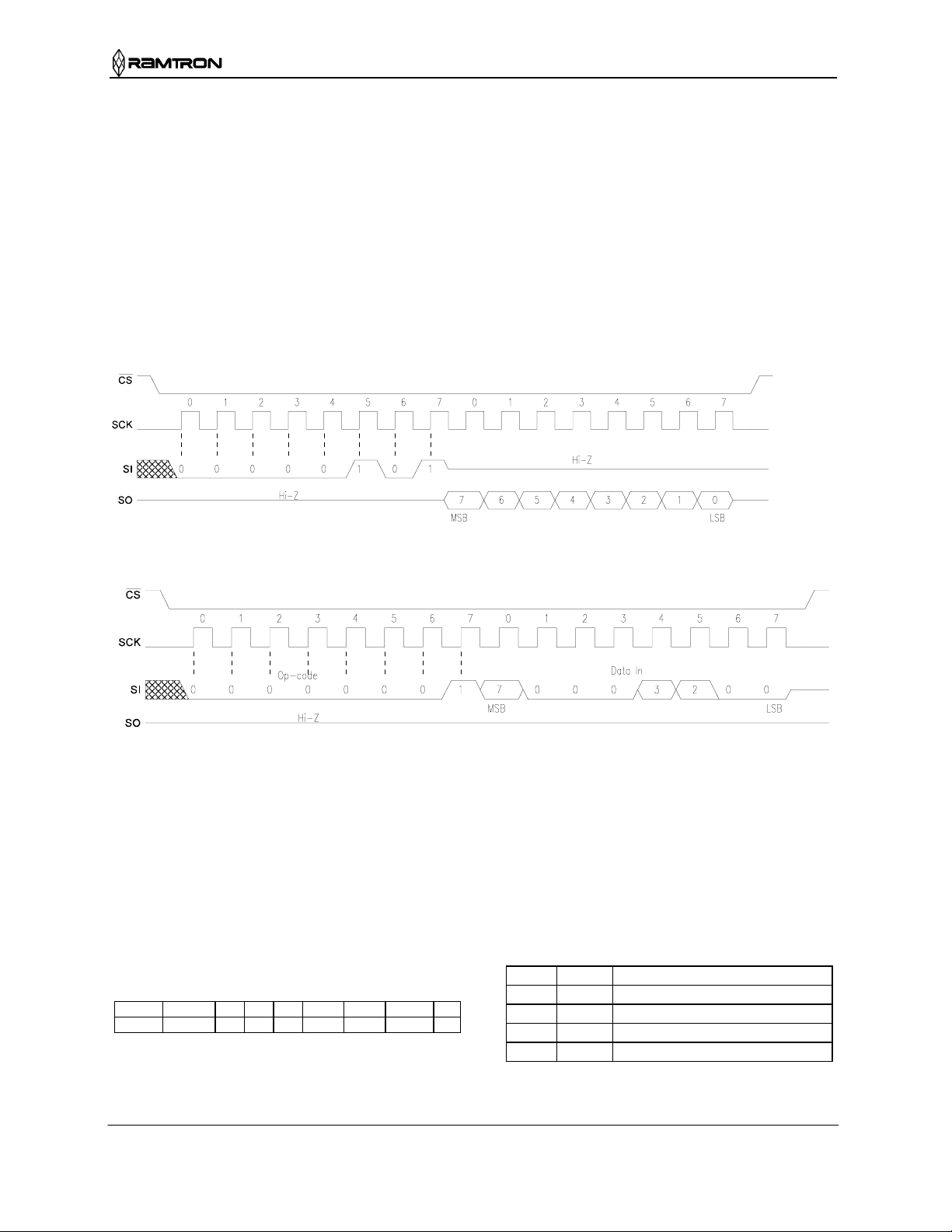
WREN - Set Write Enable Latch
The FM25CL64 will power up with writes disabled.
The WREN command must be issued prior to any
write operation. Sending the WREN op-code will
allow the user to issue subsequent op-codes for
write operations. These include writing the status
register and writing the memory.
Sending the WREN op-code causes the internal
Write Enable Latch to be set. A flag bit in the status
register, called WEL, indicates the state of the latch.
WEL=1 indicates that writes are permitted.
Attempting to write the WEL bit in the status
register has no effect. Completing any write
operation will automatically clear the write-enable
latch and prevent further writes without another
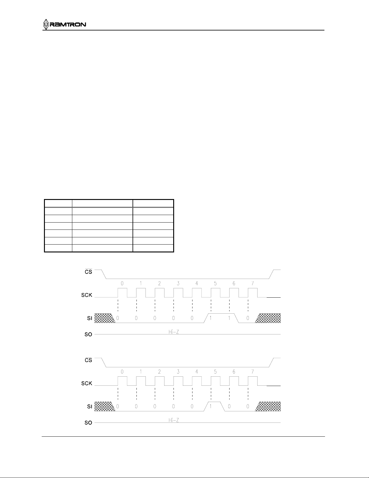
WREN command. Figure 5 below illustrates the
WREN command bus configuration.
WRDI - Write Disable
The WRDI command disables all write activity by
clearing the Write Enable Latch. The user can verify
that writes are disabled by reading the WEL bit in
the status register and verifying that WEL=0. Figure
6 illustrates the WRDI command bus configuration.
Figure 5. WREN Bus Configuration
Figure 6. WRDI Bus Configuration
Rev. 0.3
Jan. 2002 Page 5 of 13
Page 6
FM25CL64
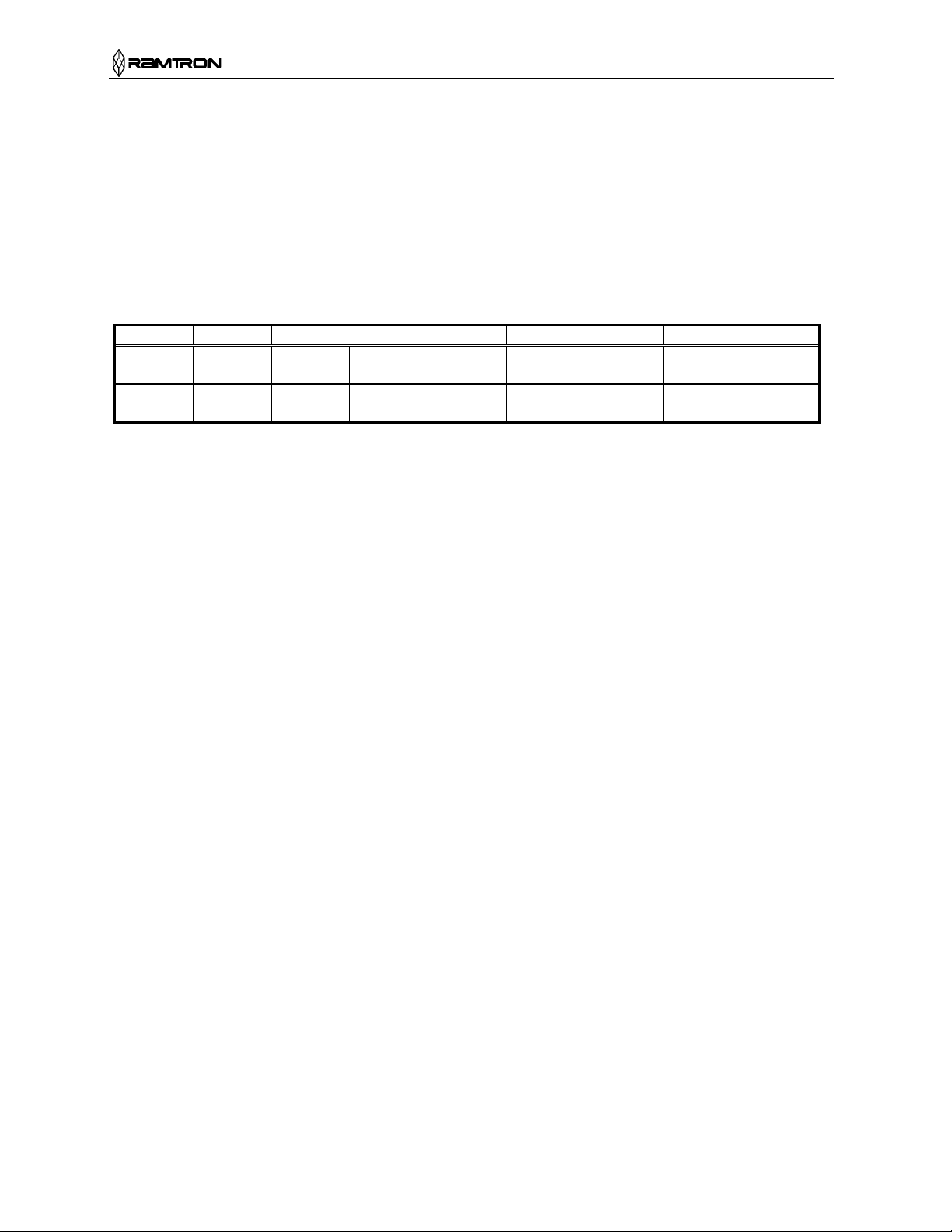
RDSR - Read Status Register
The RDSR command allows the bus master to verify
the contents of the Status register. Reading Status
provides information about the current state of the
write protection features. Following the RDSR opcode, the FM25CL64 will return one byte with the
contents of the Status register. The Status register is
described in detail in a later section.
Figure 7. RDSR Bus Configuration
WRSR – Write Status Register
The WRSR command allows the user to select
certain write protection features by writing a byte to
the Status register. Prior to issuing a WRSR
command, the /WP pin must be high or inactive.
Note that on the FM25CL64, /WP only prevents
writing to the Status register, not the memory array.
Prior to sending the WRSR command, the user must
send a WREN command to enable writes. Note that
executing a WRSR command is a write operation
and therefore clears the Write Enable Latch. The bus
configuration of RDSR and WRSR are shown
below.
Figure 8. WRSR Bus Configuration
protection features. They are nonvolatile! The WEL
Status Register & Write Protection
The write protection features of the FM25CL64 are
multi-tiered. First, a WREN op-code must be issued
prior to any write operation. Assuming that writes are
enabled using WREN, writes to memory are
controlled by the Status register. As described above,
writes to the status register are performed using the
WRSR command and subject to the /WP pin. The
Status register is organized as follows.
Table 2. Status Register
Bit 7 6 5 4 3 2 1 0
Name WPEN 0 0 0 BP1 BP0 WEL 0
Bits 0 and 4-6 are fixed at 0 and can not be modified.
flag indicates the state of the Write Enable Latch.
Writing the WEL bit in the status register has no
effect.
BP1 and BP0 are memory block write protection
bits. They specify portions of memory that are write
protected as shown in the following table.
Table 3. Block Memory Write Protection
BP1 BP0 Protected Address Range
0 0 None
0 1 1800h to 1FFFh (upper ¼)
1 0 1000h to 1FFFh (upper ½)
1 1 0000h to 1FFFh (all)
Note that the Ready bit in many EEPROMs is
unnecessary as the FRAM writes in real-time and is
never busy. The WPEN, BP1 and BP0 control write
Rev. 0.3
Jan. 2002 Page 6 of 13
Page 7
FM25CL64
The BP1 and BP0 bits and the Write Enable Latch
are the only mechanisms that protect the memory
from writes. The remaining write protection features
protect inadvertent changes to the block protect bits.
The WPEN bit controls the effect of the hardware
/WP pin. When WPEN is low, the /WP pin is
ignored. W hen WPEN is high, the /WP pin contr ols
write access to the status register. Thus the Status
register is write protected if WPEN=1 and /WP=0.
This scheme provides a write protection mechanism,
which can prevent software from writing the
memory under any circumstances. This occurs if the
BP1 and BP0 are set to 1, the WPEN bit is set to 1,
and /WP is set to 0. This occurs because the block
protect bits prevent writing memory and the /WP
signal in hardware prevents altering the block
protect bits (if WPEN is high). Therefore in this
condition, hardware must be involved in allowing a
write operation. The following table summarizes the
write protection conditions.
Table 4. Write Protection
WEL WPEN /WP Protected Blocks Unprotected Blocks Status Register
0 X X Protected Protected Protected
1 0 X Protected Unprotected Unprotected
1 1 0 Protected Unprotected Protected
1 1 1 Protected Unprotected Unprotected
Memory Operation
The SPI interface, which is capable of a relatively
high clock frequency, highlights the fast write
capability of the FRAM technology. Unlike SPI-bus
EEPROMs, the FM25CL64 can perform sequential
writes at bus speed. No page register is needed and
any number of sequential writes may be performed.
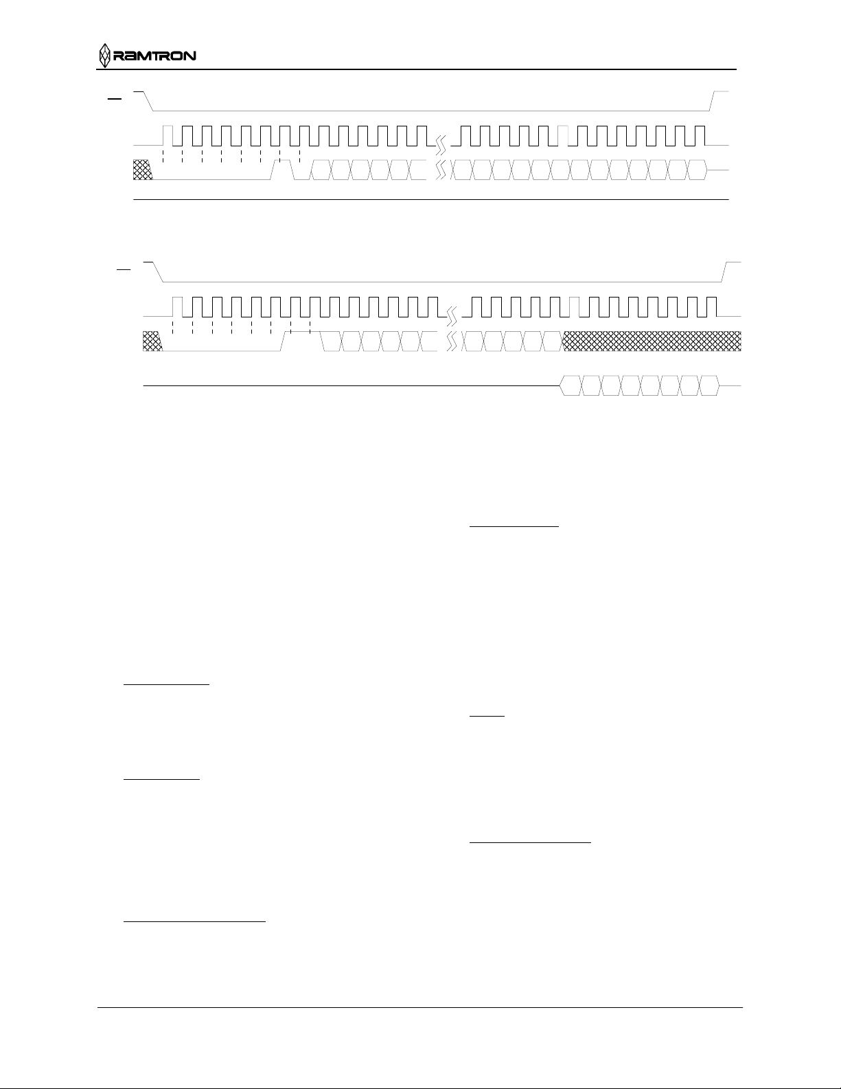
Write Operation
All writes to the memory array begin with a WREN
op-code. The next op-code is the WRITE instruction.
This op-code is followed by a two-byte address
value. The upper 3-bits of the address are ignored. In
total, the 13-bits specify the address of the first byte
of the write operation. Subsequent bytes are data and
they are written sequentially. Addresses are
incremented internally as long as the bus master
continues to issue clocks. If the last addr ess of 1FFFh
is reached, the counter will roll over to 0000h. Data is
written MSB first. A write operation is shown in
Figure 9.
Unlike EEPROMs, any number of bytes can be
written sequentially and each byte is written to
memory immediately after it is clocked in (after the
th
8
clock). The rising edge of /CS terminates a
WRITE op-code operation.
Read Operation
After the falling edge of /CS, the bus master can issue
a READ op-code. Following this instruction is a twobyte address value. The upper 3-bits of the address
are ignored. In total, the 13-bits specify the address of
the first byte of the read operation. After the op-code
and address are complete, the SI line is ignored. The
bus master issues 8 clocks, with one bit read out for
each. Addresses are incremented internally as long as
the bus master continues to issue clocks. If the last
address of 1FFFh is reached, the counter will roll
over to 0000h. Data is read MSB first. The rising
edge of /CS terminates a READ op-code operation.
A read operation is shown in Figure 10.
Hold
The /HOLD pin can be used to interrupt a serial
operation without aborting it. If the bus master pulls
the /HOLD pin low while SCK is low, the current
operation will pause. Taking the /HOLD pin high
while SCK is low will resume an operation. The
transitions of /HOLD must occur while SCK is low,
but the SCK pin can toggle during a hold state.
Rev. 0.3
Jan. 2002 Page 7 of 13
Page 8
FM25CL64
CS
0 1 2 345670 1 2 345 345670 1 2 34567
SCK
13-bit Address
Data
LSB MSB LSB
SI
SO
op-code
0 0 0 0 0 0 1 0
X X X121110 4 3 2 1 0 7 6 5 4 3 2 1 0
MSB
Figure 9. Memory Write
CS
0 1 2 345670 1 2 345 345670 1 2 34567
SCK
13-bit Address
LSB MSB LSB
76543210
Data
SI
SO
op-code
0 0 0 0 0 0 1
XXX121110 43210
1
MSB
Figure 10. Memory Read
corrupted. The fast write of FRAM is complete
Applications
The versatility of FRAM technology fits into many
diverse applications. The strength of higher write
endurance and faster writes make FRAM superior to
EEPROM in all but one-time programmable
applications. The advantage is most obvious in data
collection environments where writes are frequent
and data must be nonvolatile.
The attributes of fast writes and high write endurance
combine in many innovative ways. A short list of
ideas is provided here.
1. Data collection
save data, FRAM provides a superior alternative to
other solutions. It is more cost effective than battery
backup for SRAM and provides better write attributes
than EEPROM.
2. Configuration
retain a configuration. However, if the configuration
changes and power failure is a possibility, the higher
write endurance of FRAM allows changes to be
recorded without restriction. Any time the systemstate is altered, the change can be written. This avoids
writing to memory on power-down when the
available time is short and power scarce.
3. High noise environments
in a noisy environment can be challenging. When
severe noise or power fluctuations are present, the
long write time of EEPROM creates a window of
. In applications that collect and
. Any nonvolatile memory can
. Writing to EEPROM
within a microsecond. This time is typically too short
for noise or power fluctuations to disturb it.
4. Time to market
. In a complex system, multiple
software routines may need to access the nonvolatile
memory. In this environment the time delay
associated with programming EEPROM adds
complexity to the software development. Each
software routine must wait for complete
programming before allowing access to the next
routine. When time to market is critical, FRAM can
eliminate this simple obstacle. As soon as a write is
issued to the FM25CL64, it is effectively done -- no
waiting.
5. RF/ID
. In the area of contactless memory,
FRAM provides an ideal solution. Since RF/ID
memory is powered by an RF field, the long
programming time and high current consumption
needed to write EEPROM is unattractive. FRAM
provides a superior solution. The FM25CL64 is
suitable for multi-chip RF/ID products.
6. Maintenance tracking
. In sophisticated systems,
the operating history and system-state during a failure
is important knowledge. Maintenance can be
expedited when this information has been recorded.
Due to the high write endurance, FRAM makes an
ideal system log. In addition, the convenient interface
of the FM25CL64 allows memory to be distributed
throughout the system using minimal additional
resources.
vulnerability during which the write can be
Rev. 0.3
Jan. 2002 Page 8 of 13
Page 9
FM25CL64
Electrical Specifications
Absolute Maximum Ratings
Symbol Description Ratings
VDD Power Supply Voltage with respect to VSS -1.0V to +5.0V
VIN Voltage on any pin with respect to VSS -1.0V to +5.0V
and V
T
Storage Temperature
STG
T
Lead Temperature (Soldering, 10 seconds)
Stresses above those listed under Absolute Maximum Ratings may cause permanent damage to the device.
This is a stress rating only, and the functional operation of the device at these or any other conditions
above those listed in the operational section of this specification is not implied. Exposure to absolute
maximum ratings conditions for extended periods may affect device reliability.
LEAD
DC Operating Conditions (T
= -40° C to + 85° C, VDD = 3.0V to 3.65V unless otherwise specified)
A
Symbol Parameter Min Typ Max Units Notes
VDD Power Supply Voltage 3.0 3.3 3.65 V
IDD VDD Supply Current
@ SCK = 1.0 MHz
@ SCK = 5.0 MHz
@ SCK = 20.0 MHz
0.2
1.4
5
ISB Standby Current - 1
ILI Input Leakage Current - 10
ILO Output Leakage Current - 10
VIH Input High Voltage 0.7 VDD V
VIL Input Low Voltage -0.3 0.3 VDD V
VOH Output High Voltage
@ I
= -2 mA
OH
VOL Output Low Voltage
= 2 mA
@ I
OL
V
Input Hysteresis 0.05 VDD - V 4
HYS
– 0.8 - V
V
DD
- 0.4 V
Notes
SCK toggling between VDD-0.3V and VSS, other inputs VSS or VDD-0.3V.
1.
2. SCK = SI = /CS=V
3. V
≤ VIN ≤ VDD and VSS ≤ V
SS
. All inputs VSS or VDD.
DD
OUT
≤ VDD.
4. Characterized but not 100% tested in production.
< VDD+1.0V
IN
-40°C to + 85°C
300° C
0.8
3.0
10.0
+ 0.5 V
DD
mA
µA
µA
µA
1
2
3
3
Rev. 0.3
Jan. 2002 Page 9 of 13
Page 10
FM25CL64
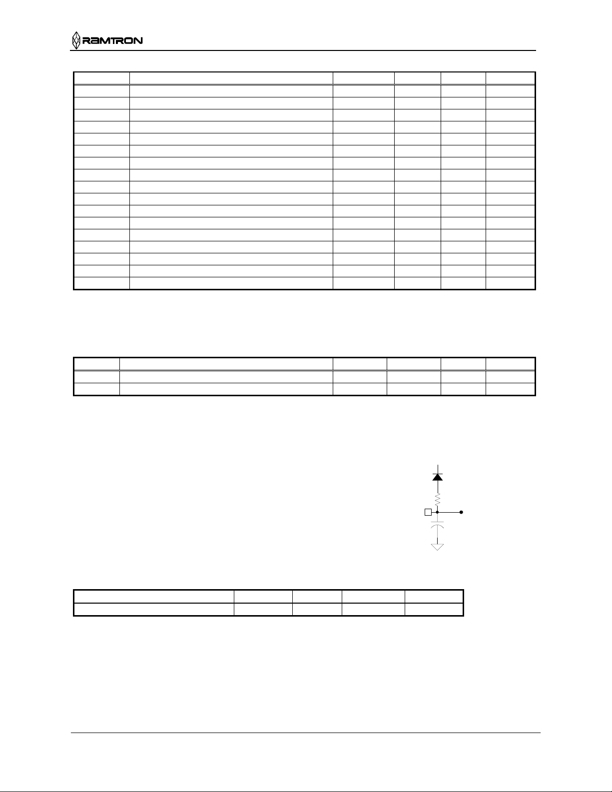
AC Parameters (TA = -40° C to + 85° C, CL = 30pF, VDD = 3.0V to 3.65V unless otherwise specified)
Symbol Parameter
Min Max
Units Notes
fCK SCK Clock Frequency 0 20 MHz
tCH Clock High Time 22 ns 1
tCL Clock Low Time 22 ns 1
t
Chip Select Setup 10 ns
CSU
t
Chip Select Hold 10 ns
CSH
tOD Output Disable Time 20 ns 2
t
Output Data Valid Time 20 ns
ODV
tOH Output Hold Time 0 ns
tD Deselect Time 60 ns
tR Data In Rise Time 50 ns 1,3
tF Data In Fall Time 50 ns 1,3
tSU Data Setup Time 5 ns
tH Data Hold Time 5 ns
tHS /Hold Setup Time 10 ns
tHH /Hold Hold Time 10 ns
tHZ /Hold Low to Hi-Z 20 ns 2
tLZ /Hold High to Data Active 20 ns 2
Notes
1. tCH + tCL = 1/fCK.
2. Characterized but not 100% tested in production.
3. Rise and fall times measured between 10% and 90% of waveform.
Capacitance (T
= 25° C, f=1.0 MHz, VDD = 3.3V)
A
Symbol Parameter Min Max Units Notes
CO Output capacitance (SO) - 8 pF 1
CI Input capacitance - 6 pF 1
Notes
1. This parameter is periodically sampled and not 100% tested.
AC Test Conditions
Input Pulse Levels 10% and 90% of V
DD
Equivalent AC Load Circuit
1.3V
Input rise and fall times 5 ns
Input and output timing levels 30% and 70% of V
DD
1100
Output
Ω
30 pF
Data Retention (V
= 3.0V to 3.65V unless otherwise specified)
DD
Parameter Min Max Units Notes
Data Retention 10 - Years 1
Notes
The relationship between retention, temperature, and the associated reliability level is characterized
1.
separately. Endurance is the guaranteed number of read- or write-cycles per address that can be
performed while maintaining the specified data retention. It is unlikely to reach this limit for most
applications.
Rev. 0.3
Jan. 2002 Page 10 of 13
Page 11
FM25CL64
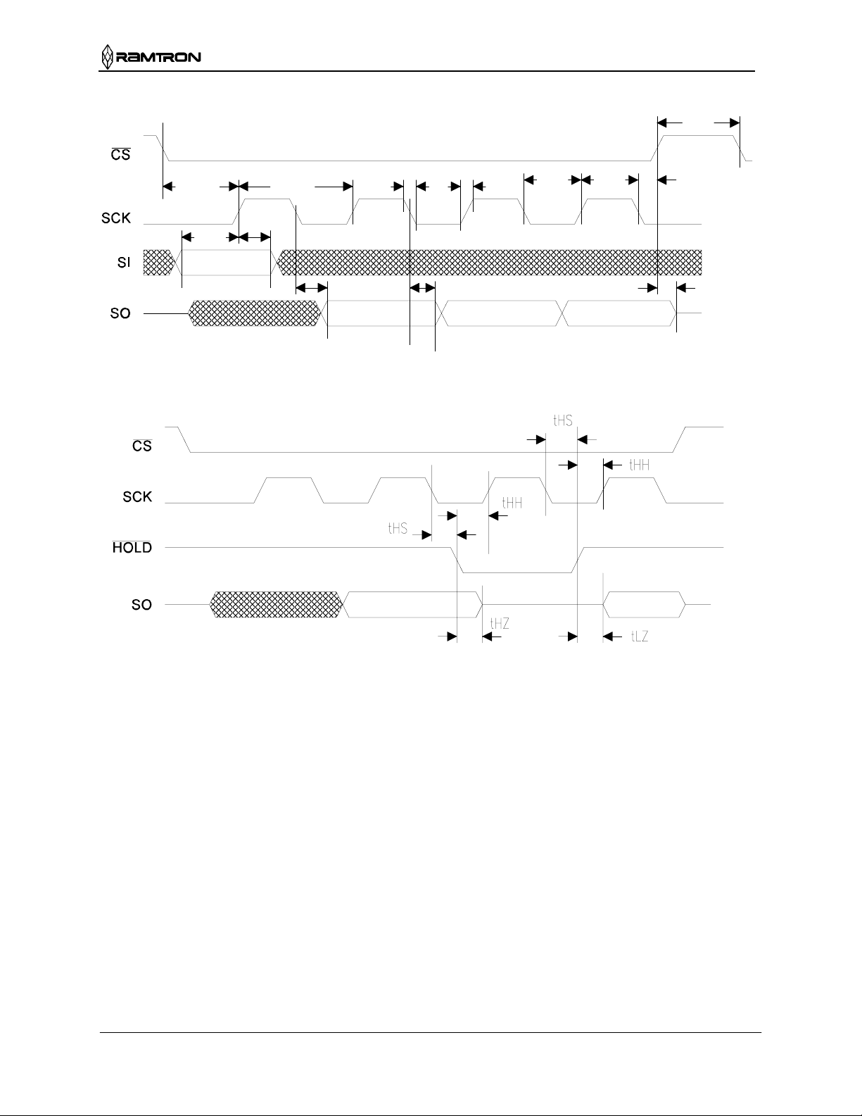
Serial Data Bus Timing
tD
/Hold Timing
tCSU
tSU
tH
1/fCK
tRtF
tCL tCH
tCSH
tODV tOH tOD
Rev. 0.3
Jan. 2002 Page 11 of 13
Page 12
FM25CL64
α
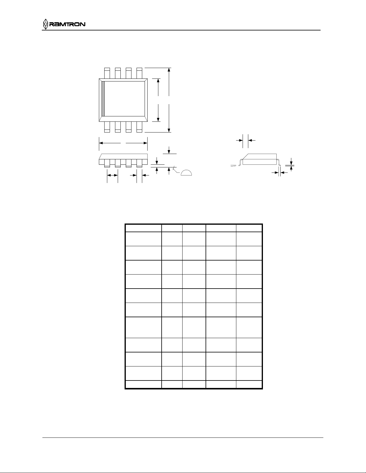
Mechanical Drawing (8-pin SOP - JEDEC Standard MS-012)
Index
Area
E H
Pin 1
D
A
B
e
Selected Dimensions
Symbol Dim Min Nom. Max
A mm
A1 mm
B mm
C mm
D mm
E mm
e mm
H mm
h mm
L mm
α
Refer to JEDEC MS-012 for complete dimensions and notes.
Controlling dimensions in millimeters.
A1
in.
in.
in.
in.
in.
in.
in.
in.
in.
in.
.10 mm
.004 in.
1.35
0.053
0.10
0.004
0.33
0.013
0.19
0.007
4.80
0.189
3.80
0.150
1.27 BSC
0.050
5.80
0.228
0.25
0.010
0.40
0.016
0°
h
°
45
1.75
0.069
0.25
0.010
0.51
0.020
0.25
0.010
5.00
0.197
4.00
0.157
BSC
6.20
0.244
0.50
0.197
1.27
0.050
8°
L
C
Rev. 0.3
Jan. 2002 Page 12 of 13
Page 13

FM25CL64
Revision History
Revision
0.0 5/10/01 Initial Release
0.1 7/5/01 Up dated AC and DC specifications. Changed AC Test Conditions and Load
0.2 10/11/01 Added unlimited endurance bullet. Changed Data Retention table.
0.3 1/8/02 Changed operating Vdd voltage range to 3.0 – 3.65V. Reduced Idd supply
Date
Summary
Circuit.
current limits.
Rev. 0.3
Jan. 2002 Page 13 of 13
 Loading...