

Page 1

BODY EXTERIOR, DOORS, ROOF & VEHICLE SECURITY
Revision: October 2006
2007 G35 Sedan
SECTION EXT
A
B
CONTENTS
SYMPTOM DIAGNOSIS ...............................2
SQUEAK AND RATTLE TROUBLE DIAG-
NOSES ................................................................
Work Flow .................................................................2
Inspection Procedure ............. ... ... ... .... ......................4
Diagnostic Worksheet ...............................................6
PRECAUTION ...............................................8
PRECAUTIONS ...................................................8
Precaution for Supplemental Restrain t System
(SRS) "AIR BAG" and "SEAT BELT PRE-TEN-
SIONER" ...................................................................
Precaution for Procedure without Cowl Top Cover ......8
Precaution for Work ..................................... .............8
PREPARATION ............................................9
PREPARATION ...................................................9
Special Service Tools ...... ... .... ... ... ... .... ... ...................9
Commercial Service Tools .......................................9
ON-VEHICLE REPAIR .................................10
FRONT BUMPER ...............................................10
Exploded View ........................................................10
Removal and Installation ........ ... ... ...........................11
REAR BUMPER .................................................13
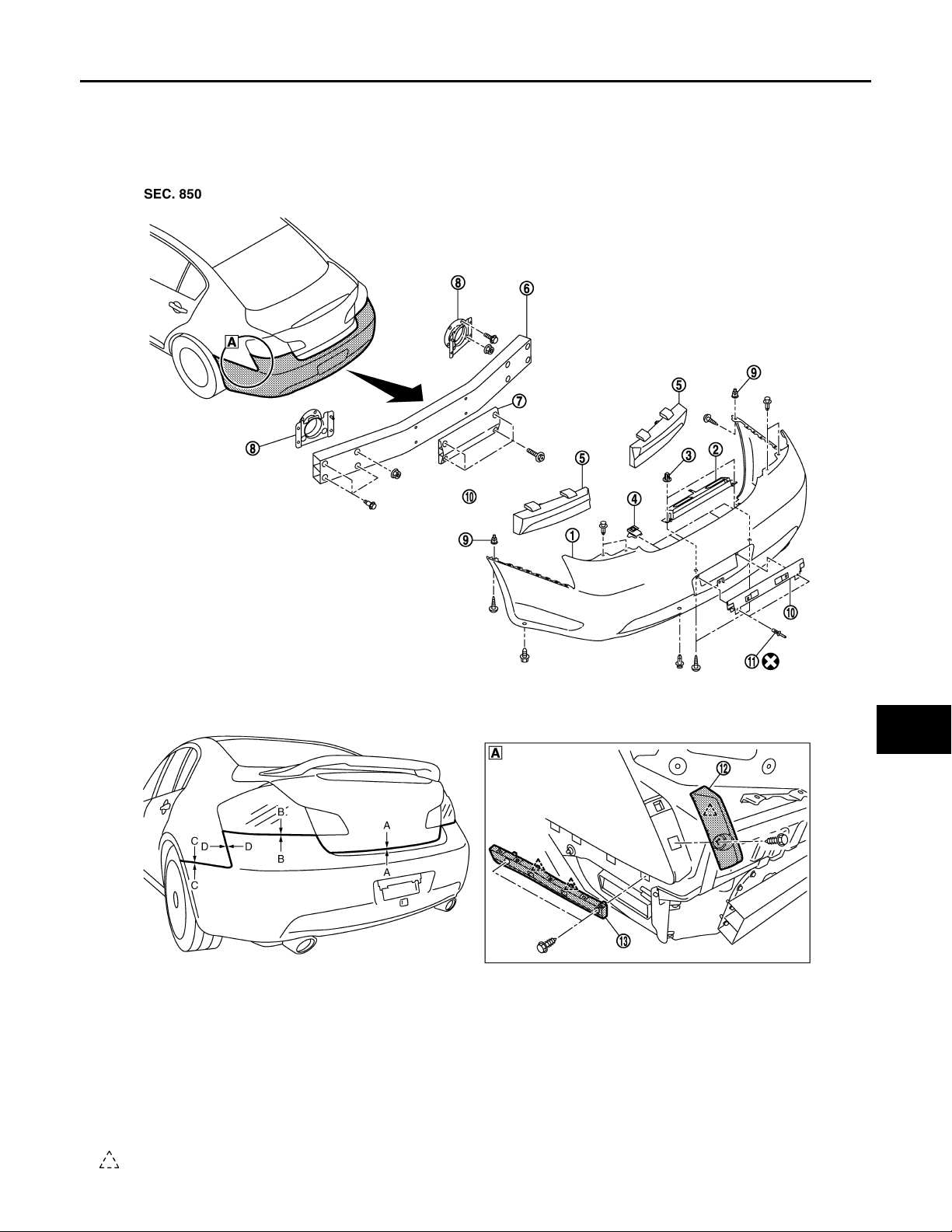
Exploded View ........................................................13
Removal and Installation ........ ... ... ...........................14
FRONT GRILLE .................................................16
Exploded View ........................................................16
Removal and Installation ........ ... ... ...........................16
COWL TOP .........................................................18
EXTERIOR
Exploded View .........................................................18
Removal and Installation .........................................18
FENDER PROTECTOR ....................................21
2
8
Exploded View .........................................................21
Removal and Installation .........................................22
CENTER MUD GUARD .....................................24
Exploded View .........................................................24
Removal and Installation .........................................24
FLOOR SIDE FAIRING .....................................26
Exploded View .........................................................26
Removal and Installation .........................................26
ROOF SIDE MOLDING .....................................28
Exploded View .........................................................28
Removal and Installation .........................................28
DOOR SASH MOLDING ...................................30
Exploded View .........................................................30
Removal and Installation .........................................30
DOOR OUTSIDE MOLDING .............................32
Exploded View .........................................................32
Removal and Installation .........................................32
DOOR PARTING SEAL ....................................34
Exploded View .........................................................34
Removal and Installation .........................................34
TRUNK LID FINISHER ......................................35
Exploded View .........................................................35
Removal and Installation .........................................35
REAR SPOILER ................................................37
Exploded View .........................................................37
Removal and Installation .........................................37
C
D
E
F
G
H
I
J
EXT
L
M
N
O
P
EXT-1
Page 2
SQUEAK AND RATTLE TROUBLE DIAGNOSES
Revision: October 2006
2007 G35 Sedan
< SYMPTOM DIAGNOSIS >
SYMPTOM DIAGNOSIS
SQUEAK AND RATTLE TROUBLE DIAGNOSES
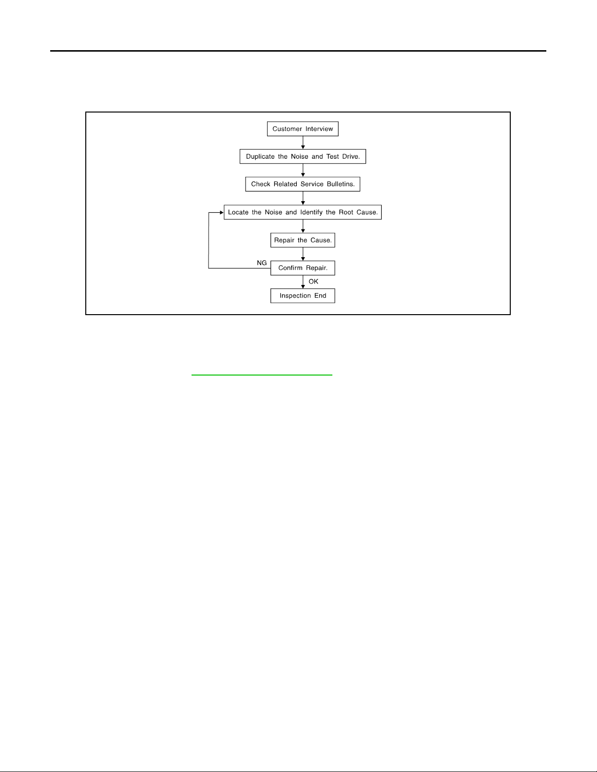
Work Flow INFOID:0000000000961786
SBT842
CUSTOMER INTERVIEW
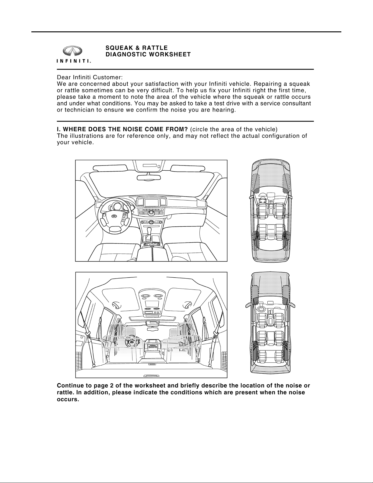
Interview the customer if possible, to determine the conditions that exist when the noise occurs. Use the Diagnostic Worksheet during the interview to document the facts and conditions when the noise occurs and any of
customer's comments; refer to EXT-6, "
conditions that exist when the noise occurs.
• The customer may not be able to provide a det ailed description or the location of the noise. Attempt to obtai n
all the facts and conditions that exist when the noise occurs (or does not occur).
• If there is more than one noise in the vehicle, perform a diagnosis and repair the noise that the customer is
concerned about. This can be accomplished by performing a cruise test on the vehicle with the customer.
• After identifying the type of noise, isolate the noise in terms of its characteristics. The noise characteristics
are provided so the customer, service adviser and technician are all speaking the same language when
defining the noise.
• Squeak —(Like tennis shoes on a clean floor)
Squeak characteristics include the light contact/fast movement/brought on by road conditions/hard surfaces=higher pitch noise/softer surfaces=lower pitch noises/edge to surface=chirping
• Creak—(Like walking on an old wooden floor)
Creak characteristics include firm contact/slow movement/twisting with a rotational movement/pitch dependent on materials/often brought on by activity.
• Rattle—(Like shaking a baby rattle)
Rattle characteristics include the fast repeated contact/vibration or similar movement/loose parts/missing
clip or fastener/incorrect clearance.
• Knock —(Like a knock on a door)
Knock characteristics include hollow sounding/sometimes repeating/often brought on by driver action.
• Tick—(Like a clock second hand)
Tick characteristics include gentle contacting of light materials/loose components/can be caused by driver
action or road conditions.
• Thump—(Heavy, muffled knock noise)
Thump characteristics include softer knock/dead sound often brought on by activity.
• Buzz—(Like a bumblebee)
Buzz characteristics include high frequency rattle/firm contact.
• Often the degree of accept able noise level will vary depending up on the person. A noi se that you may judge
as acceptable may be very irritating to the customer.
• Weather conditions, especially humidity and temperature, may have a great effect on noise level.
Diagnostic Worksheet". This information is necessary to duplicate the
DUPLICATE THE NOISE AND TEST DRIVE
EXT-2
Page 3

SQUEAK AND RATTLE TROUBLE DIAGNOSES
Revision: October 2006
2007 G35 Sedan
< SYMPTOM DIAGNOSIS >
If possible, drive the vehicle with the customer until the noise is duplicated. Note any additional information on
the Diagnostic Worksheet regarding the conditions or location of the noise. This information can be used to
duplicate the same conditions when you confirm the repair.
If the noise can be duplicated easily during the test drive, to help identify the source of the noise, try to duplicate the noise with the vehicle stopped by doing one or all of the following:
1) Close a door.
2) Tap or push/pull around the area where the noise appears to be coming from.
3) Rev the engine.
4) Use a floor jack to recreate vehicle “twist”.
5) At idle, apply engine load (electrical load, half-clutch on M/T models, drive position on A/T models).
6) Raise the vehicle on a hoist and hit a tire with a rubber hammer.
• Drive the vehicle and attempt to duplicate the conditions the customer states exist when the noise occurs.
• If it is difficult to duplicate the noise, drive the vehicle slowly on an undulating or rough road to stress the
vehicle body.
A
B
C
D
CHECK RELATED SERVICE BULLETINS
After verifying the customer concern or symptom, check ASIST for Technical Service Bulletins (TSBs) related
to that concern or symptom.
If a TSB relates to the symptom, follow the procedure to repair the noise.
LOCATE THE NOISE AND IDENTIFY THE ROOT CAUSE
1. Narrow down the noise to a general area. To help pinpoint the source of the noise, use a listening tool
(Chassis Ear: J-39570, Engine Ear and mechanics stethoscope).
2. Narrow down the noise to a more specific area and identify the cause of the noise by:
• removing the components in the area that you suspect the noise is coming from.
Do not use too much force when removing clips and fasteners, otherwise clips and fastener can be broken
or lost during the repair, resulti ng in the creation of new noise.
• tapping or pushing/pulling the component that you suspect is causing the noise.
Do not tap or push/pull the component with excessive force, otherwise the noise will be eliminated only temporarily.
• feeling for a vibration with your hand by touching the component(s) that you suspect is (are) causing the
noise.
• placing a piece of paper between components that you suspect are causing the noise.
• looking for loose components and contact marks.
Refer to EXT- 4, "
Inspection Procedure".
REPAIR THE CAUSE
• If the cause is a loose component, tighten the component securely.
• If the cause is insufficient clearance between components:
- separate components by repositioning or loosening and retightening the component, if possible.
- insulate components with a suitable insulator such as urethane p ads, foam blocks, felt cloth tape or urethane
tape. A Nissan Squeak and Rattle Kit (J-43980) is available through your authorized Nissan Parts Department.
CAUTION:
Do not use excessive force as many components are constructed of plastic and may be damaged.
NOTE:
Always check with the Parts Department for the latest parts information.
The following materials are contained in the Nissan Squeak and Rattle Kit (J-43980). Each item can be
ordered separately as needed.
URETHANE PADS [1.5 mm (0.059 in) thick]
Insulates connectors, harness, etc.
76268-9E005: 100 × 135 mm (3.94 × 5.31 in)/76884-71L01: 60 × 85 mm (2.36 × 3.35 in)/7688471L02:15 × 25 mm (0.59 × 0.98 in)
INSULATOR (Foam blocks)
Insulates components from contact. Can be used to fill space behind a panel.
73982-9E000: 45 mm (1.77 in) thick, 50 × 50 mm (1.97 × 1.97 in)/7398250Y00: 10 mm (0.39 in) thick, 50 × 50 mm (1.97 × 1.97 in)
INSULATOR (Light foam block)
80845-71L00: 30 mm (1.18 in) thick, 30 × 50 mm (1.18 × 1.97in)
FELT CLOTHTAPE
Used to insulate where movement does not occur. Ideal for instrument panel applications.
E
F
G
H
I
J
EXT
L
M
N
O
P
EXT-3
Page 4

SQUEAK AND RATTLE TROUBLE DIAGNOSES
Revision: October 2006
2007 G35 Sedan
< SYMPTOM DIAGNOSIS >
68370-4B000: 15 × 25 mm (0.59 × 0.98 in) pad/68239-13E00: 5 mm (0.20 in) wide tape roll
The following materials, not found in the kit, can also be used to repair squeaks and rattles.
UHMW (TEFLON) TAPE
Insulates where slight movement is present. Ideal for instrument panel applications.
SILICONE GREASE
Used in place of UHMW tape that will be visible or not fit. Will only last a few months.
SILICONE SPRAY
Use when grease cannot be applied.
DUCT TAPE
Use to eliminate movement.
CONFIRM THE REPAIR
Confirm that the cause of a noise is repaired by test driving the vehicle.Operate the vehicle under the same
conditions as when the noise originally occurred. Refer to the notes on the Diagnostic Worksheet.
Inspection Procedure INFOID:0000000000961787
Refer to Table of Contents for specific component removal and installationinformation.
INSTRUMENT PANEL
Most incidents are caused by contact and movement between:
1. The cluster lid A and instrument panel
2. Acrylic lens and combination meter housing
3. Instrument panel to front pillar garnish
4. Instrument panel to windshield
5. Instrument panel mounting pins
6. Wiring harnesses behind the combination meter
7. A/C defroster duct and duct joint
These incidents can usually be located by tapping or moving the components to duplicate the noise or by
pressing on the components while driving to stop the noise. Most of these incidents can be repaired by
applying felt cloth tape or silicon spray (in hard to reach areas). Urethane pads can be used to insulate
wiring harness.
CAUTION:
Do not use silicone spray to isolate a squeak or rattle. If you saturatethe area with silicone, you
will not be able to recheck the repair.
CENTER CONSOLE
Components to pay attention to include:
1. Shifter assembly cover to finisher
2. A/C control unit and cluster lid C
3. Wiring harnesses behind audio and A/C control unit
The instrument panel repair and isolation procedures also apply to thecenter console.
DOORS
Pay attention to the:
1. Finisher and inner panel making a slapping noise
2. Inside handle escutcheon to door finisher
3. Wiring harnesses tapping
4. Door striker out of alignment causing a popping noise on startsand stops
Tapping or moving the components or pressing on them while driving to duplicate the conditions can isolate
many of these incidents. You can usually insulate the areas with felt cloth tape or insulator foam blocks from
the Nissan Squeak and Rattle Kit (J-43980) to repair the noise.
TRUNK
Trunk noises are often caused by a loose jack or loose items put intothe trunk by the owner.
In addition look for:
1. Trunk lid dumpers out of adjustment
2. Trunk lid striker out of adjustment
EXT-4
Page 5

SQUEAK AND RATTLE TROUBLE DIAGNOSES
Revision: October 2006
2007 G35 Sedan
< SYMPTOM DIAGNOSIS >
3. The trunk lid torsion bars knocking together
4. A loose license plate or bracket
Most of these incidents can be repaired by adjusting, securing or insulatingthe item(s) or component(s) caus-
ing the noise.
SUNROOF/HEADLINING
Noises in the sunroof/headlining area can often be traced to one of the following:
1. Sunroof lid, rail, linkage or seals making a rattle or light knockingnoise
2. Sunvisor shaft shaking in the holder
3. Front or rear windshield touching headlining and squeaking
Again, pressing on the components to stop the noise while duplicatingthe conditions can isolate most of these
incidents. Repairs usually consistof insulating with felt cloth tape.
SEATS
When isolating seat noise it's important to note the position the seatis in and the load placed on the seat when
the noise is present. These conditionsshould be duplicated when verifying and isolating the cause of the
noise.
Cause of seat noise include:
1. Headrest rods and holder
2. A squeak between the seat pad cushion and frame
3. The rear seatback lock and bracket
These noises can be isolated by moving or pressing on the suspectedcomponents while duplicating the condi-
tions under which the noise occurs.Most of these incidents can be repaired by repositioning the component
orapplying urethane tape to the contact area.
UNDERHOOD
Some interior noise may be caused by components under the hood or onthe engine wall. The noise is then
transmitted into the passenger compartment.
Causes of transmitted underhood noise include:
1. Any component mounted to the engine wall
2. Components that pass through the engine wall
3. Engine wall mounts and connectors
4. Loose radiator mounting pins
5. Hood bumpers out of adjustment
6. Hood striker out of adjustment
These noises can be difficult to isolate since they cannot be reached from the interior of the vehicle. The best
method is to secure, move or insulate one component at a time and test drive the vehicle. Also, engine RPM
or load can be changed to isolate the noise. Repairs can usually be made by moving, adjusting, securing, or
insulating the component causing the noise.
A
B
C
D
E
F
G
H
I
J
EXT
L
M
N
O
P
EXT-5
Page 6
SQUEAK AND RATTLE TROUBLE DIAGNOSES
Revision: October 2006
2007 G35 Sedan
< SYMPTOM DIAGNOSIS >
Diagnostic Worksheet
INFOID:0000000000961788
PIIB8741E
EXT-6
Page 7
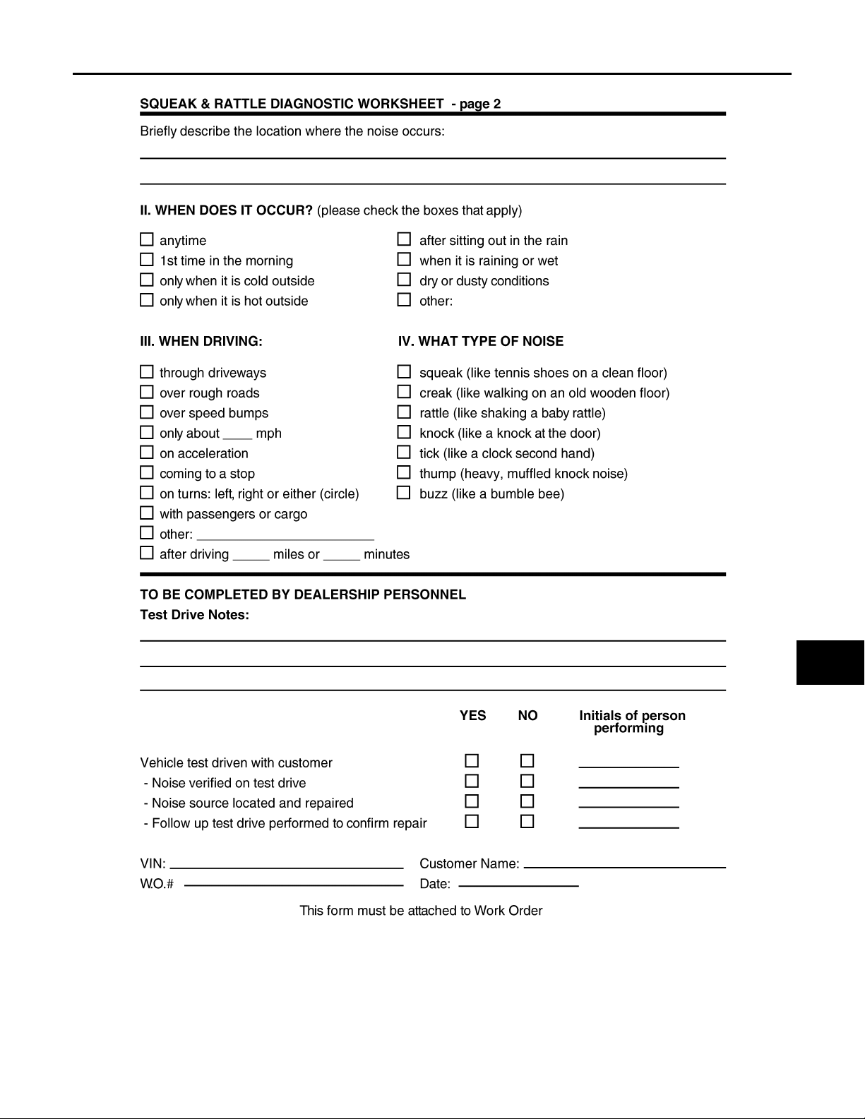
SQUEAK AND RATTLE TROUBLE DIAGNOSES
Revision: October 2006
2007 G35 Sedan
< SYMPTOM DIAGNOSIS >
A
B
C
D
E
F
G
H
I
J
EXT
L
M
N
O
PIIB8742E
P
EXT-7
Page 8
PRECAUTIONS
Revision: October 2006
2007 G35 Sedan
< PRECAUTION >
PRECAUTION
PRECAUTIONS
Precaution for Supplemental Restraint System (SRS) "AIR BAG" and "SEAT BELT PRE-TENSIONER" INFOID:0000000000961789
The Supplemental Restraint System such as “AIR BAG” and “SEAT BELT PRE-TENSIONER”, used along
with a front seat belt, helps to reduce the risk or severity of injury to the driver and front passenger for certain
types of collision. This system includes seat belt switch inputs and dual stage front air bag modules. The SRS
system uses the seat belt switches to determine the front air bag deployment, and may only deploy one front
air bag, depending on the severity of a collision and whether the front occupants are belted or unbelted.
Information necessary to service the system safely is included in the SRS and SB section of this Service Manual.
WARNING:
• To avoid rendering the SRS inoperative, which could increase the risk of personal injury or death in
the event of a collision which would result in air bag inflation, all maintenance must be performed by
an authorized NISSAN/INFINITI dealer.
• Improper maintenance, including incorrect removal and installation of the SRS, can lead to personal
injury caused by unintentional activation of the system. For removal of Spiral Cable and Air Bag
Module, see the SRS section.
• Do not use electrical test equipment on any circuit related to the SRS unless instructed to in this
Service Manual. SRS wiring harnesses can be identified by yellow and/or orange harnesses or harness connectors.
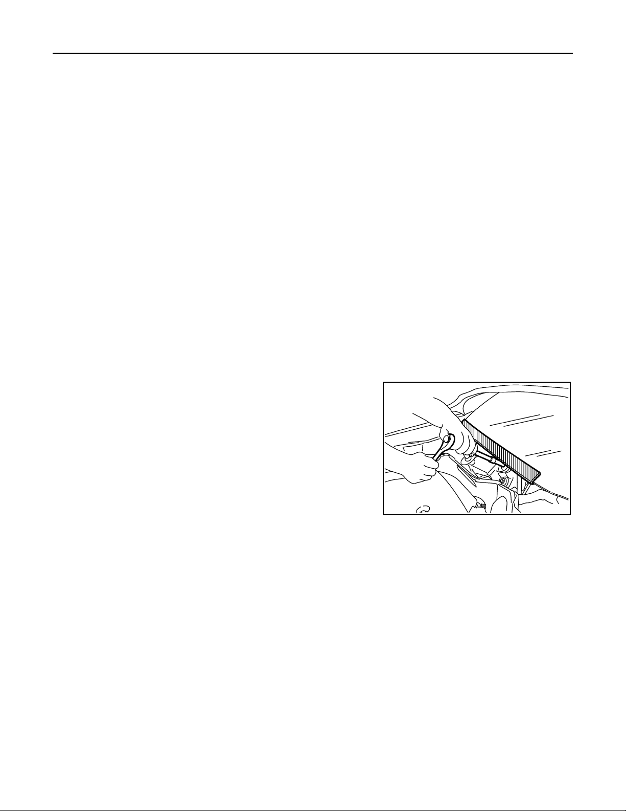
Precaution for Procedure without Cowl Top Cover INFOID:0000000000961790
When performing the procedure after removing cowl top cover, cover
the lower end of windshield with urethane, etc.
PIIB3706J
Precaution for Work INFOID:0000000000961791
• After removing and inst alling the opening/closing p arts, be sure to carry out fitting adjustments to check their
operation.
• Check the lubrication level, damage, and wear of each part. If necessary, grease or replace it.
EXT-8
Page 9
< PREPARATION >
Revision: October 2006
2007 G35 Sedan
PREPARATION
PREPARATION
PREPARATION
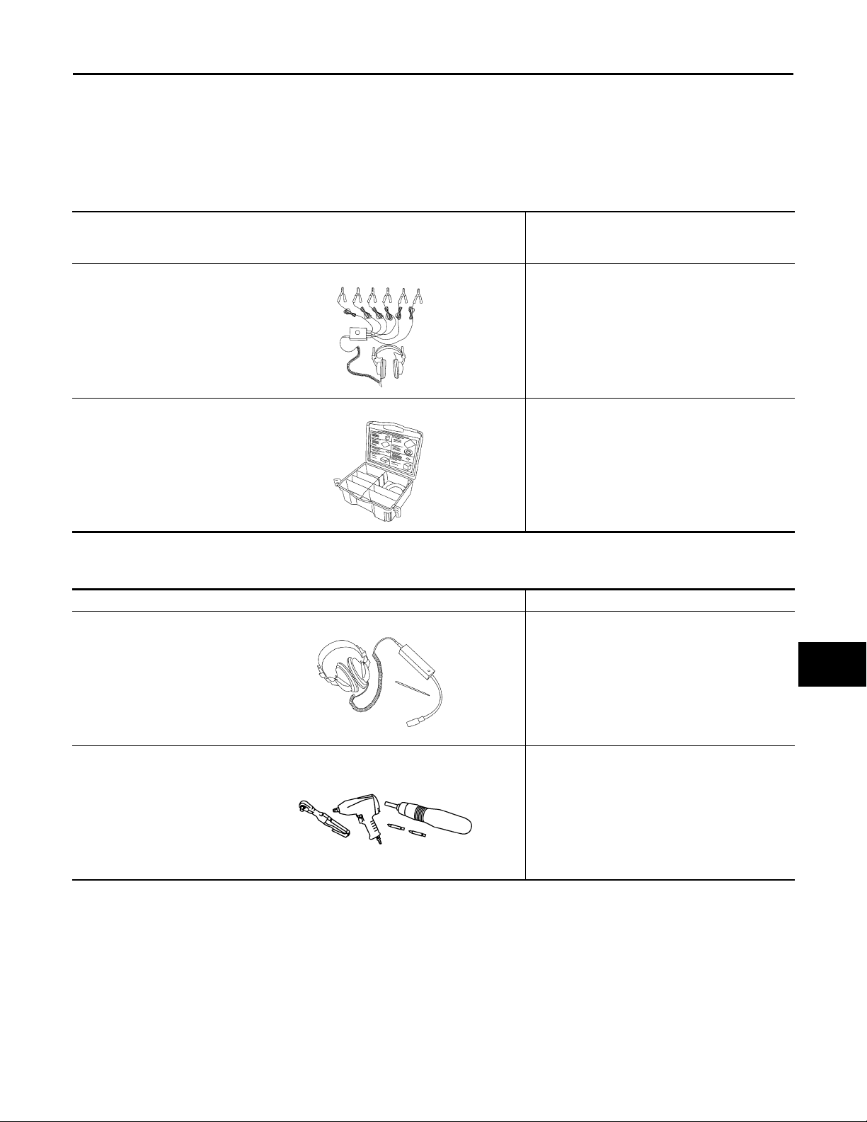
Special Service Tools INFOID:0000000000961792
The actual shapes of Kent-Moore tools may differ from those of special service tools illustrated here.
Tool number
(Kent-Moore No.)
Tool name
(J-39570)
Chassis ear
SIIA0993E
(J-43980)
NISSAN Squeak and Rattle
Kit
SIIA0994E
Description
Location the noise
Repairing the cause of noise
A
B
C
D
E
F
G
H
Commercial Service Tools INFOID:0000000000961793
Tool name Description
Engine ear Locating the noise
SIIA0995E
Power tool
PIIB1407E
I
J
EXT
L
M
N
O
P
EXT-9
Page 10
FRONT BUMPER
B
Revision: October 2006
2007 G35 Sedan
< ON-VEHICLE REPAIR >
ON-VEHICLE REPAIR
FRONT BUMPER
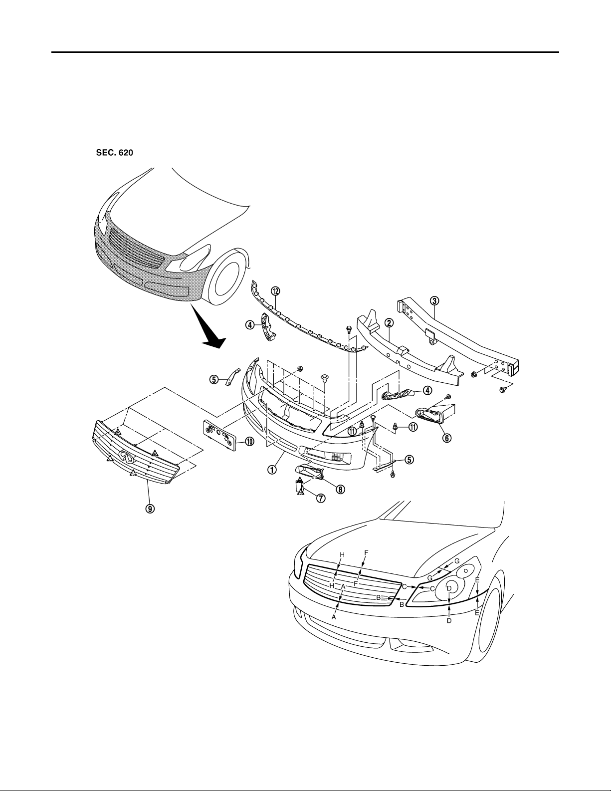
Exploded View INFOID:0000000000961794
1. Bumper fascia asse mbly 2. Energy absorber 3. Bumper reinforcement
4. Bumper side stiffener 5. Bumper side bracket 6. Bumper finisher A
7. Bumper finisher B 8. Bumper finisher 9. Front grille
10. License plate bracket 11. Grommet 12. Hood seal assembly (front)
JMKIA0074G
EXT-10
Page 11
< ON-VEHICLE REPAIR >
B
B
B
B
Revision: October 2006
2007 G35 Sedan
Clip
Pawl
FRONT BUMPER
A
Removal and Installation INFOID:0000000000961795
REMOVAL
CAUTION:
Bumper fascia is made of resin. Do not apply strong force to it, and be careful to prevent contact with
oil.
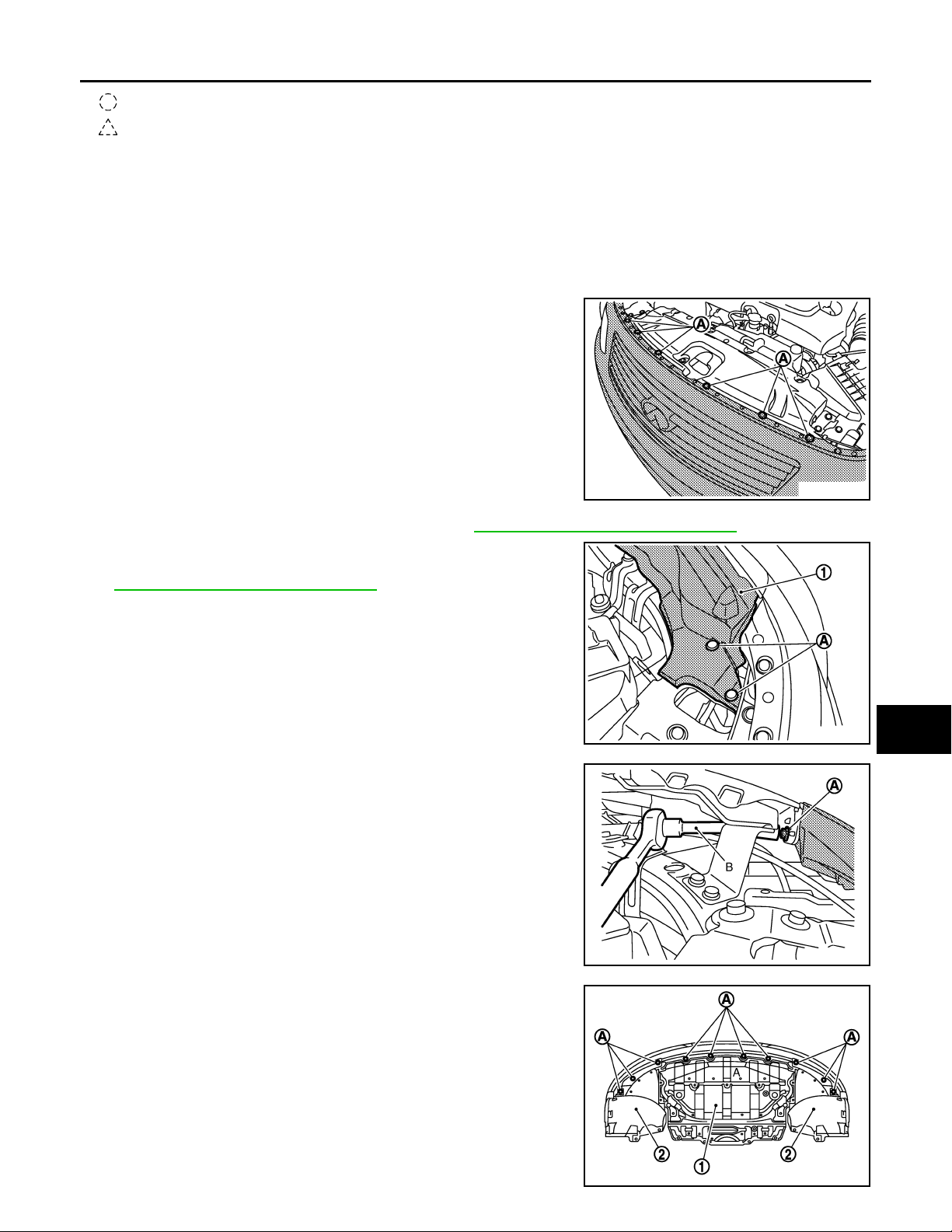
1. Fully open hood assembly.
2. Remove clips (A) of front bumper fascia upper side.
JMKIA0088G
3. Remove radiator core support ornament. Refer to DLK-196, "
4. Remove clips (A) of hood seal assembly (side) LH/RH, and then
remove hood seal assembly (1) located front portion. Refer to
DLK-199, "
Removal and Installation".
Removal and Installation".
B
C
D
E
F
G
H
I
5. Remove bolts (A) of fixing bumper fascia and front fender (LH/
RH), using a tool (B).
6. Remove bolts (A) of fixing engine lower cover (1) and front
fender protector (2)
JMKIA0089G
JMKIA0090G
J
EXT
L
M
N
O
P
JMKIA0091G
EXT-11
Page 12
FRONT BUMPER
B
Revision: October 2006
2007 G35 Sedan
< ON-VEHICLE REPAIR >
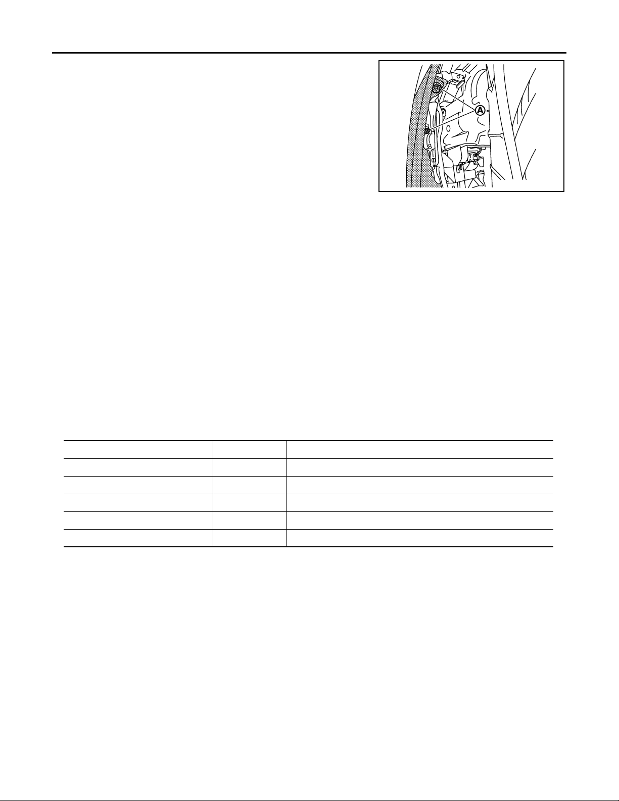
7. Remove fender protector (front) mounting bolts and clips, and
then remove screws (A) of fixing bumper fascia left and right
side.
JMKIA0092G
8. Remove bumper fascia assembly.
CAUTION:
When removing bumper fascia, 2 workers are required so as to prevent it from dropping.
9. Remove the following parts after removing bumper fascia.
• Front grille
• Hood seal assembly (front)
• License plate bracket
• Front bumper side bracket (LH/RH)
• Front bumper side stiffener (LH/RH)
• Front bumper finisher A
• Front bumper finisher B
10. Remove bumper energy absorber.
11. Remove bumper reinforcement mounting nuts and bolts, and then remove bumper reinforcement with
power tool.
INSTALLATION
Install in the reverse order of removal.
NOTE:
After installing, perform fitting adjustment.
Portion Clearance
Front bumper – Front grille A – A 0.2 – 2.8 mm (0.008 – 0.110 in)
Front bumper – Front grille B – B 0.2 – 2.8 mm (0.008 – 0.110 in)
Front bumper – Headlamp C – C 0.5 – 3.2 mm (0.020 – 0.126 in)
Front bumper – Headlamp D – D 0.5 – 3.2 mm (0.020 – 0.126 in)
Front bumper – Front fender E – E 0.0 – 0.7 mm (0.000 – 0.028 in)
EXT-12
Page 13
< ON-VEHICLE REPAIR >
B
Revision: October 2006
2007 G35 Sedan
REAR BUMPER
REAR BUMPER
Exploded View INFOID:0000000000961796
A
B
C
D
E
F
G
H
1. Bumper fascia assembly 2. Rear license lamp bracket 3. Grommet
4. Bumper clip 5. Bumper energy absorber 6. Bumper reinforcement
7. Bumper over rider 8. Bumper stay 9. Bumper grommet
10. Rear license plate bracket 11. Rivet 12. Bumper side bracket B
13. Bumper side bracket A
Pawl
I
J
EXT
L
M
N
O
JMKIA0075G
P
EXT-13
Page 14
< ON-VEHICLE REPAIR >
B
B
B
B
Revision: October 2006
2007 G35 Sedan
REAR BUMPER
Removal and Installation
INFOID:0000000000961797
REMOVAL
CAUTION:
Bumper fascia is made of resin. Do not apply strong force to it, and be careful to prevent contact with
oil.
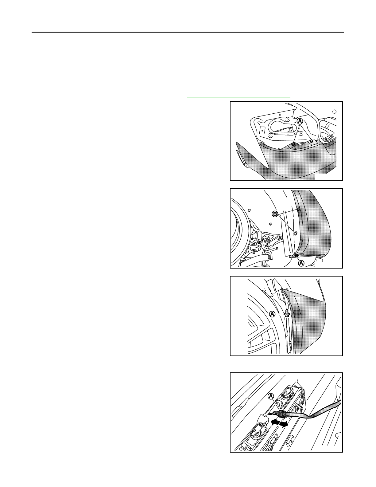
1. Fully open trunk lid assembly .
2. Remove rear combination lamp (LH/RH). Refer to EXL-198, "
3. Remove clips (A) located under rear combination lamp (LH/RH).
4. Remove screw (A) of bumper fascia underside.
5. Remove clips (B) of rear wheel house protector rear end (LH/
RH).
Removal and Installation".
JMKIA0093G
6. Remove screws (A) of bumper fascia front end upper (LH/RH).
7. Remove clips of bumper fascia underside, and then pull out bumper fascia toward rear of vehicle.
8. Disconnect license plate lamp connector (A).
JMKIA0094G
JMKIA0095G
9. Remove bumper fascia assembly.
JMKIA0096G
EXT-14
Page 15
REAR BUMPER
Revision: October 2006
2007 G35 Sedan
< ON-VEHICLE REPAIR >
CAUTION:
When removing bumper fascia, 2 workers are required so as to prevent it from dropping.
10. Remove the following parts after removing bumper fascia.
• License lamp. Refer to EXL-202, "
• License lamp bracket.
• License plate bracket.
• Bumper clip.
11. Remove bumper energy absorber.
12. Remove license lamp harness clamps of bumper reinforcement.
13. Remove bumper reinforcement mounting nuts and bolts, and then remove bumper reinforcement with
power tool.
INSTALLATION
Install in the reverse order of removal.
NOTE:
After installing, perform fitting adjustment.
Removal and Installation".
A
B
C
D
E
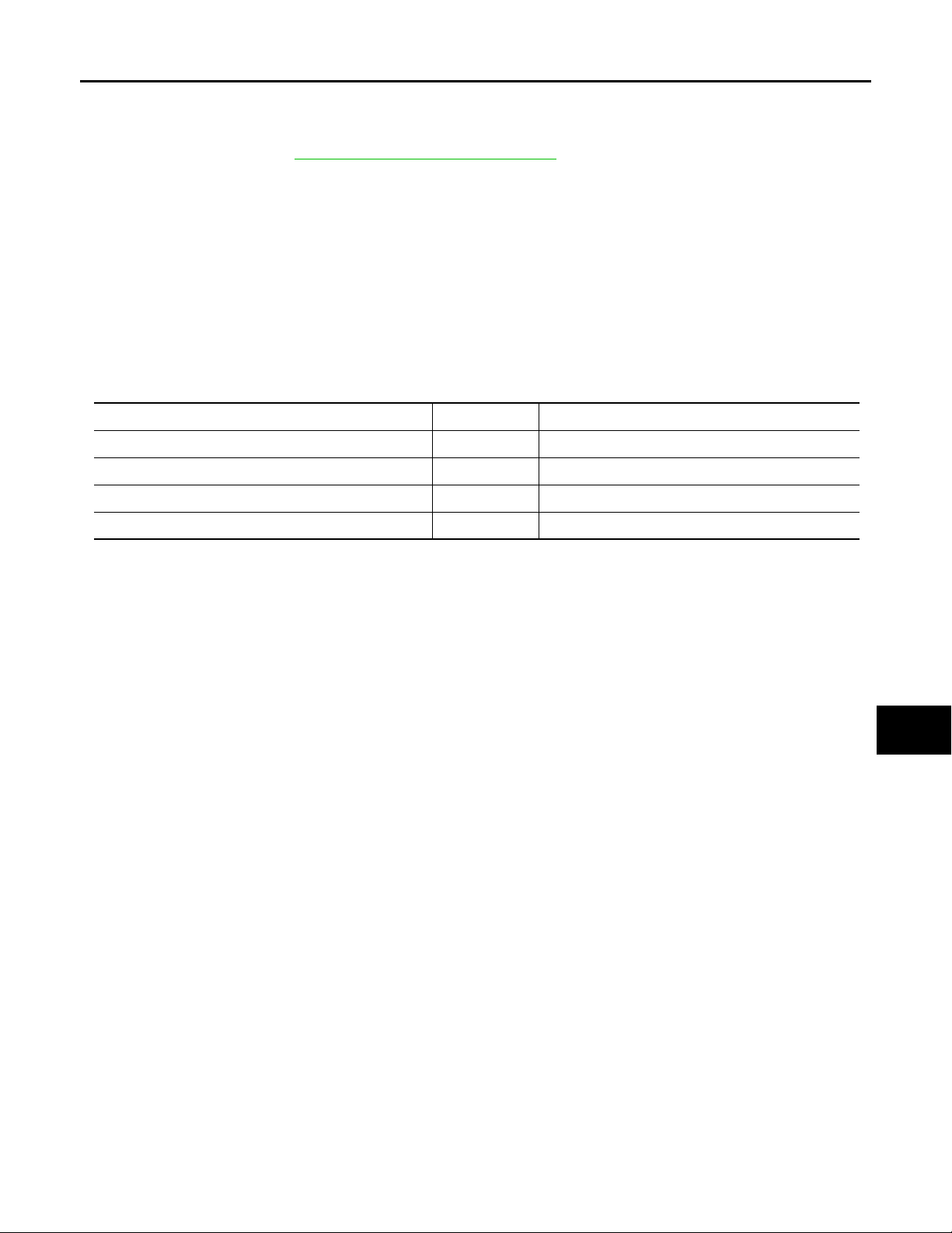
Portion Clearance
Rear bumper – Trunk lid A – A 4.0 – 8.0 mm (0.157 – 0.315 in)
Rear bumper – Rear combination lamp B – B 0.0 – 3.0 mm (0.000 – 0.118 in)
Rear bumper – Rear fender C – C 0.0 – 0.8 mm (0.000 – 0.031 in)
Rear bumper – Rear fender D – D 0.0 – 0.8 mm (0.000 – 0.031 in)
F
G
H
I
J
EXT
L
M
N
O
P
EXT-15
Page 16
FRONT GRILLE
B
B
Revision: October 2006
2007 G35 Sedan
< ON-VEHICLE REPAIR >
FRONT GRILLE
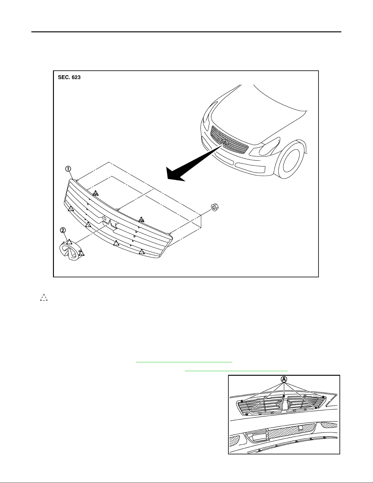
Exploded View INFOID:0000000000961798
JMKIA0076G
1. Front grille 2. Front emblem
Pawl
Removal and Installation INFOID:0000000000961799
REMOVAL
CAUTION:
Apply protection tape around outer circumference of front grille (bumper fascia side).
1. Fully open hood assembly.
2. Remove reservoir tank. Refer to CO-14, "
3. Remove radiator core support ornament. Refer to DLK-196, "
4. Remove front grille mounting nuts (A).
Removal and Installation".
Removal and Installation".
JMKIA0097G
EXT-16
Page 17
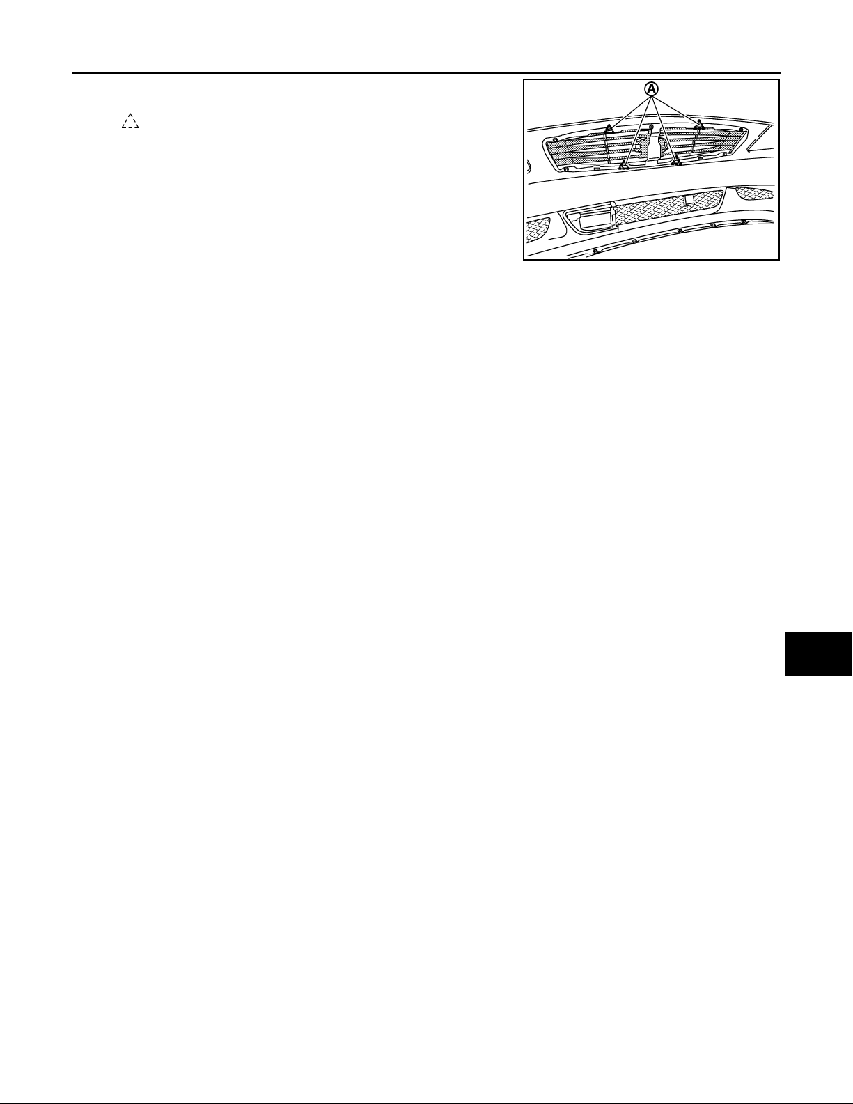
< ON-VEHICLE REPAIR >
B
Revision: October 2006
2007 G35 Sedan
5. Disengage pawls (A) of fixing front grille.
: Pawl
FRONT GRILLE
A
6. Pull front grille out toward vehicle front.
7. Remove the following parts after removing front grille.
Front emblem
INSTALLATION
Install in the reverse order of removal.
B
C
JMKIA0098G
D
E
F
G
H
I
J
EXT
L
M
N
O
P
EXT-17
Page 18
COWL TOP
B
Revision: October 2006
2007 G35 Sedan
< ON-VEHICLE REPAIR >
COWL TOP
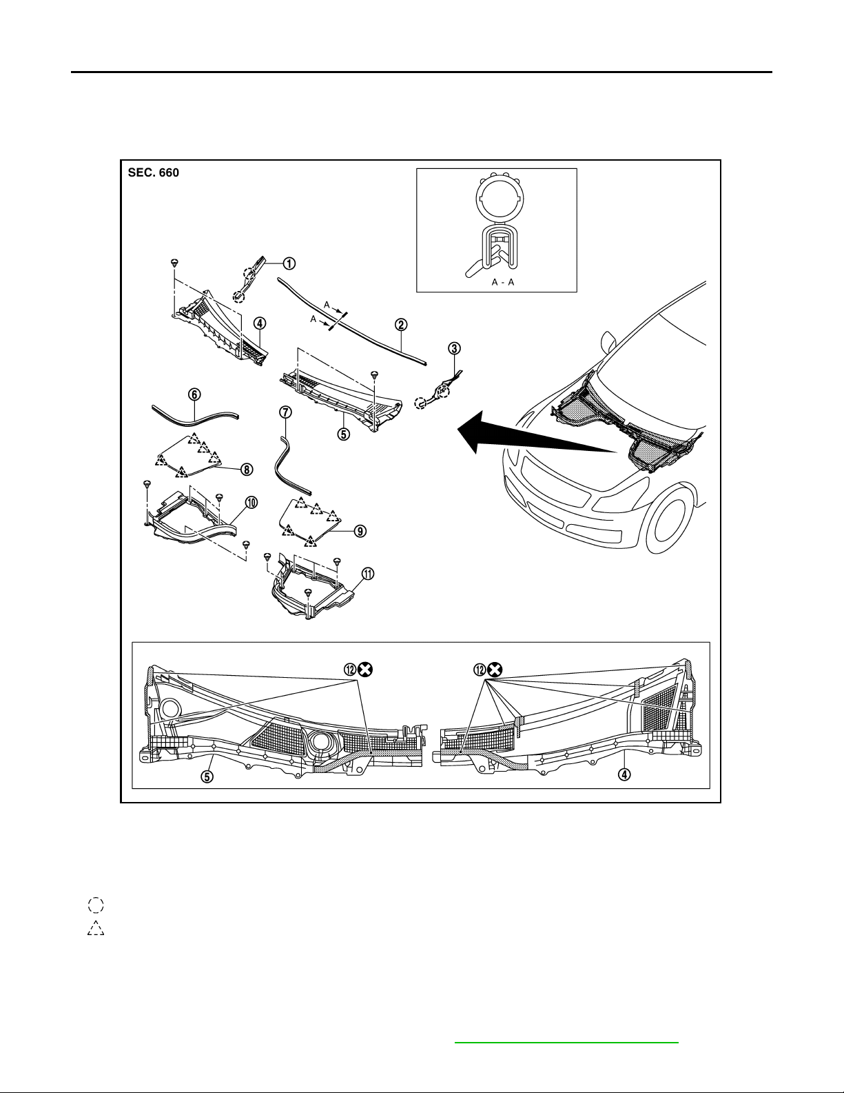
Exploded View INFOID:0000000000961800
1. Front fender cover (RH) 2. Cowl top seal 3. Front fender cover (LH)
4. Cowl top cover (RH) 5. Cowl top cover (LH) 6. Cowl top cover seal (RH)
7. Cowl top cover seal (LH) 8. Battery cover 9. Brake master cylinder cover
10. Hoodledge cover (RH) 11. Hoodledge cover (LH) 12. EPT sealer
Clip
Pawl
Removal and Installation INFOID:0000000000961801
REMOVAL
1. Fully open hood assembly.
2. Remove front wiper arm (LH/RH) from vehicle. Refer to WW-84, "
JMKIA0077G
Removal and Installation".
EXT-18
Page 19
COWL TOP
B
B
B
B
Revision: October 2006
2007 G35 Sedan
< ON-VEHICLE REPAIR >
3. Remove battery cover and brake master cylinder cover.
4. Remove hoodledge cover mounting clips and then remove hoodledge cover (LH/RH) and cowl top cover
seal (LH/RH).
5. Remove cowl top seal.
6. Remove cowl top cover mounting clips.
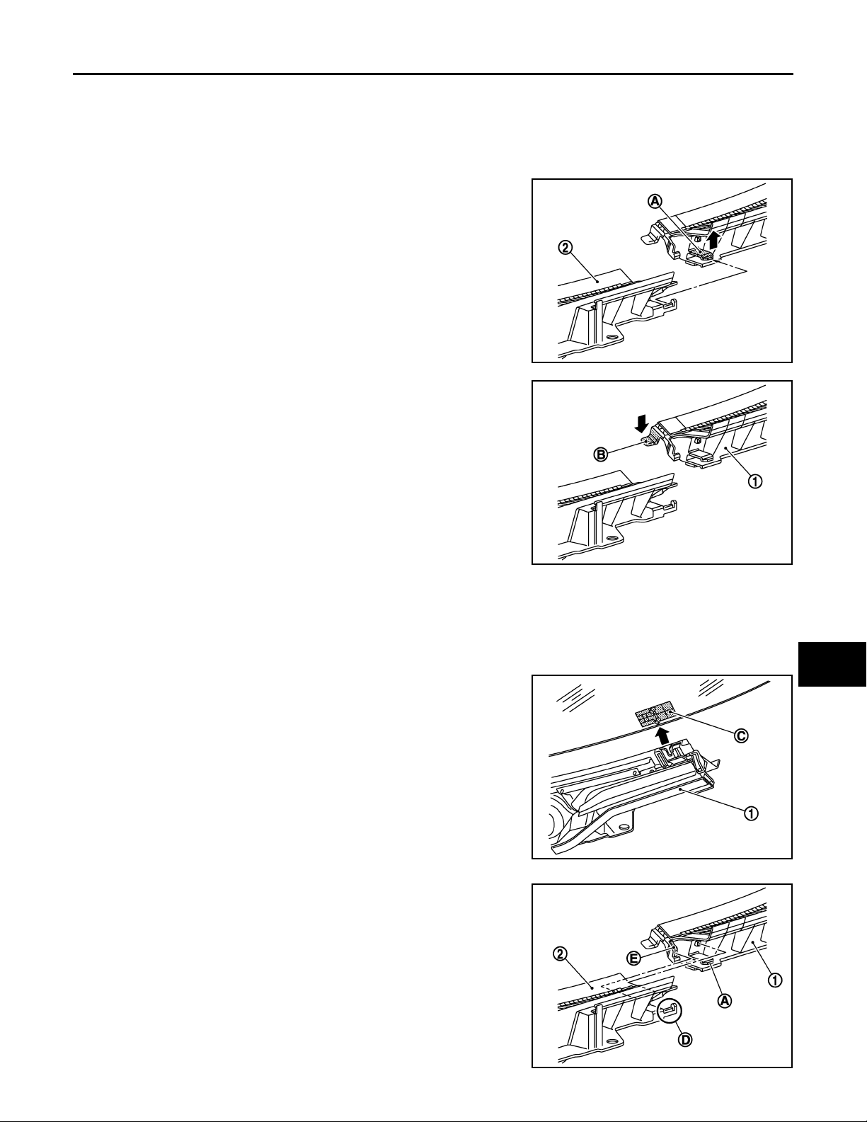
7. Plastic pawl (A) is pull up and cowl top cover RH (2) is removed
ahead of vehicles.
JMKIA0099G
A
B
C
D
E
8. Plastic pawl (B) is push down and cowl top cover LH (1) is
removed ahead of vehicles.
9. Remove the following parts after removing cowl top cover.
• Front fender cover (LH/RH).
• EPT sealer.
INSTALLATION
Note the following, and install in the reverse order of removal.
• Install cowl top cover LH (1) with (C) (pin from front windshield
glass) aligned with concave part.
JMKIA0100G
F
G
H
I
J
EXT
L
M
• Slide the pawl while aligning with the concave part of (E).
• Engage the joint of plastic pawl of (A) with (D), and then assemble
cowl top covers LH (1) and RH (2).
N
JMKIA0104G
O
P
JMKIA0105G
EXT-19
Page 20

COWL TOP
Revision: October 2006
2007 G35 Sedan
< ON-VEHICLE REPAIR >
CAUTION:
After installing, perform adjustment of wiper arm. Refer to WW-85, "
Adjustment".
EXT-20
Page 21
< ON-VEHICLE REPAIR >
B
Revision: October 2006
2007 G35 Sedan
FENDER PROTECTOR
FENDER PROTECTOR
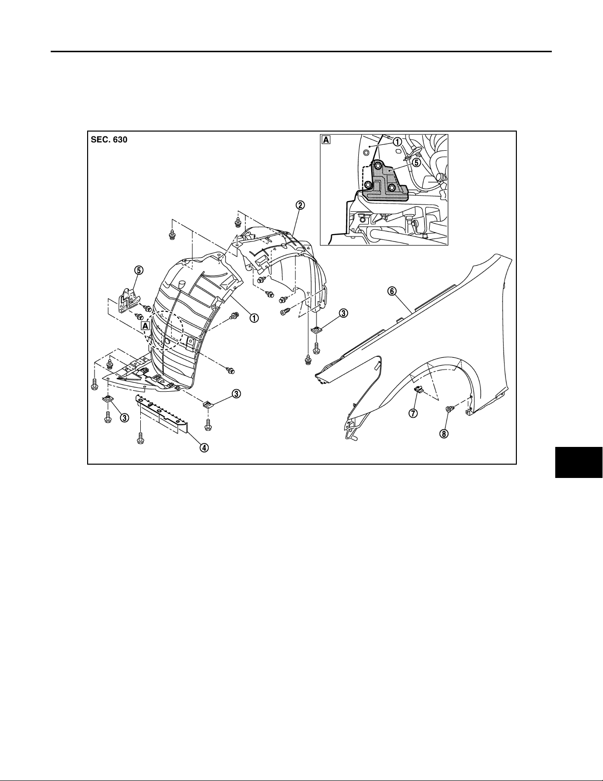
Exploded View INFOID:0000000000961802
FENDER PROTECTOR
A
B
C
D
E
F
G
H
1. Fender protector (front) 2. Fender protector (rear) 3. U-nut
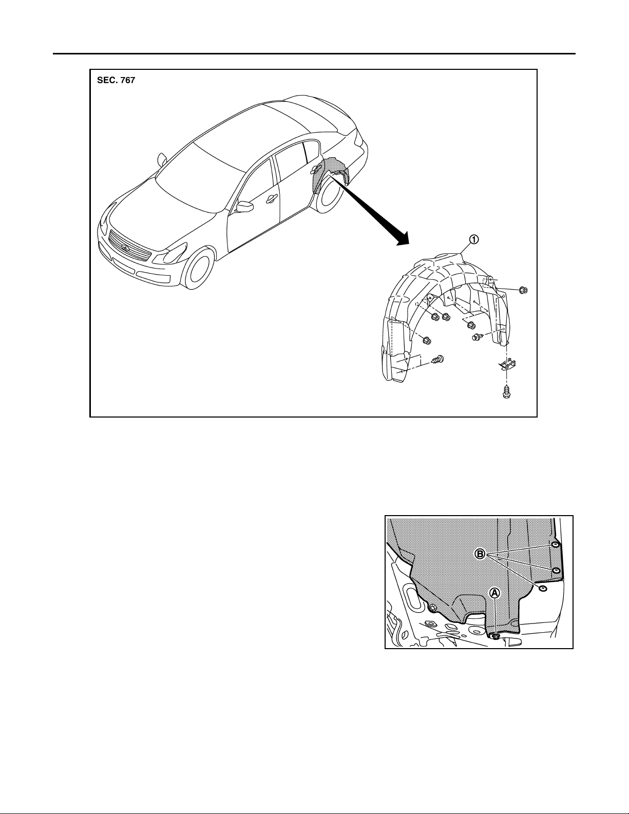
4. Fairing 5. Splash guard 6. Front fender
7. Fender clip 8. Grommet
REAR WHEEL HOUSE PROTECTOR
JMKIA0078G
I
J
EXT
L
M
N
O
P
EXT-21
Page 22
< ON-VEHICLE REPAIR >
B
B
Revision: October 2006
2007 G35 Sedan
FENDER PROTECTOR
JMKIA0079G
1. Rear wheel house protector
Removal and Installation
INFOID:0000000000961803
REMOVAL
FENDER PROTECTOR
1. Remove bolt (A) of fender protector (rear) rear end.
2. Remove screws (B) of fender protector (rear) located center
mud guard and front fender.
JMKIA0106G
3. Remove clips of fender protector (rear).
4. Remove fender clip from wheelhouse arches, and then remove fender protector (rear) from wheel house.
EXT-22
Page 23
FENDER PROTECTOR
B
B
B
Revision: October 2006
2007 G35 Sedan
< ON-VEHICLE REPAIR >
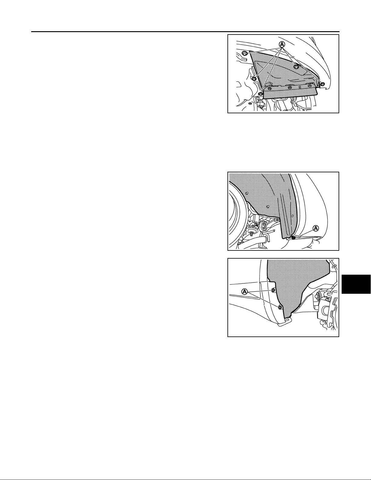
5. Remove bolts (A) of fender protector (front) located engine
under cover and front bumper.
JMKIA0107G
6. Remove fender protector (front) mounting clips.
7. Remove fender clip from wheel house arches, and then remove fender protector (front) from wheel house.
8. Remove the following parts after removing front fender protector.
• Air guide
• Fender clip
A
B
C
D
E
REAR WHEEL HOUSE PROTECTOR
1. Remove bolt (A) of rear wheel house protector rear end.
2. Remove screws (A) of rear wheel house protector located center mud guard.
JMKIA0108G
JMKIA0109G
F
G
H
I
J
EXT
L
M
3. Remove rear wheel house protector mounting nuts and then remove rear wheel house protector.
INSTALLATION
Install in the reverse order of removal.
N
O
P
EXT-23
Page 24
CENTER MUD GUARD
B
Revision: October 2006
2007 G35 Sedan
< ON-VEHICLE REPAIR >
CENTER MUD GUARD
Exploded View INFOID:0000000000961804
JMKIA0080G
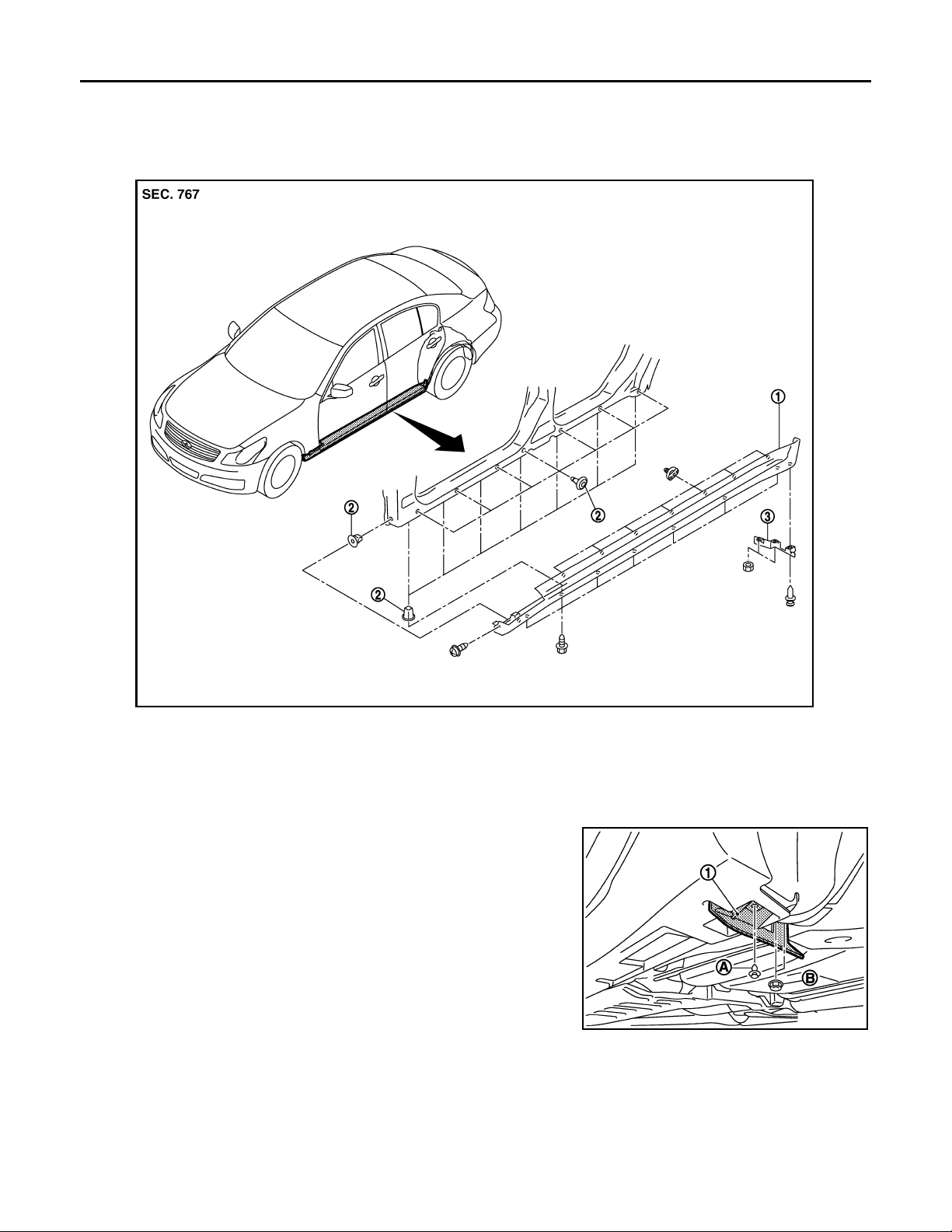
1. Center mud guard 2. Grommet 3. Wind deflector
Removal and Installation INFOID:0000000000961805
REMOVAL
1. Remove wind deflector mounting clip (A) and nuts (B), and then
remove wind deflector (1).
JMKIA0110GB
EXT-24
Page 25
CENTER MUD GUARD
Revision: October 2006
2007 G35 Sedan
< ON-VEHICLE REPAIR >
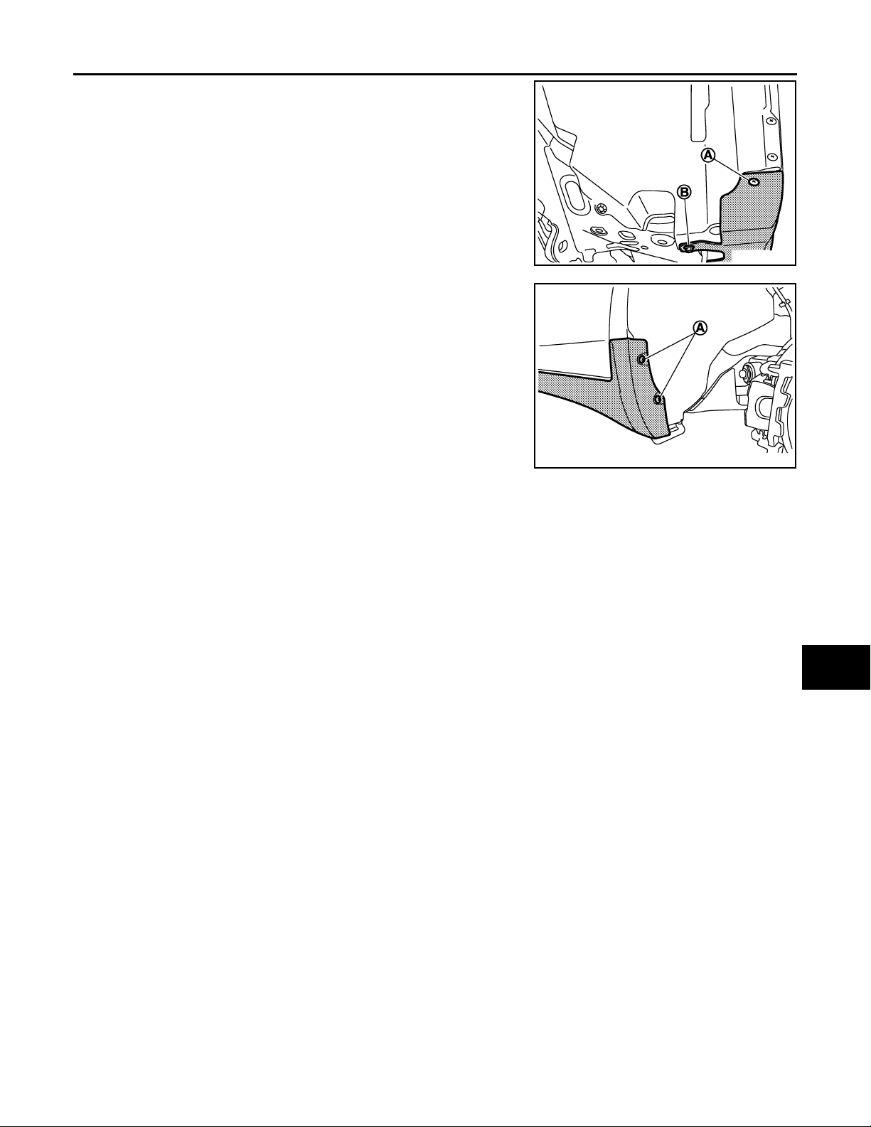
2. Remove screw (A) and bolt (B) of center mudguard front end.
3. Remove screws (A) of center mudguard rear end.
A
B
C
JMKIA0111GB
D
E
F
G
JMKIA0112GB
4. Remove screws of center mudguard underside.
5. Fully open front door and rear door.
6. Remove clips from back of center mudguard using remover tool.
7. Remove center mudguard from body side.
INSTALLATION
Install in the reverse order of removal.
CAUTION:
When installing center mud guard, make sure that clips are securely fitted in panel holes on body, and
then press them in.
H
I
J
EXT
L
M
N
O
P
EXT-25
Page 26
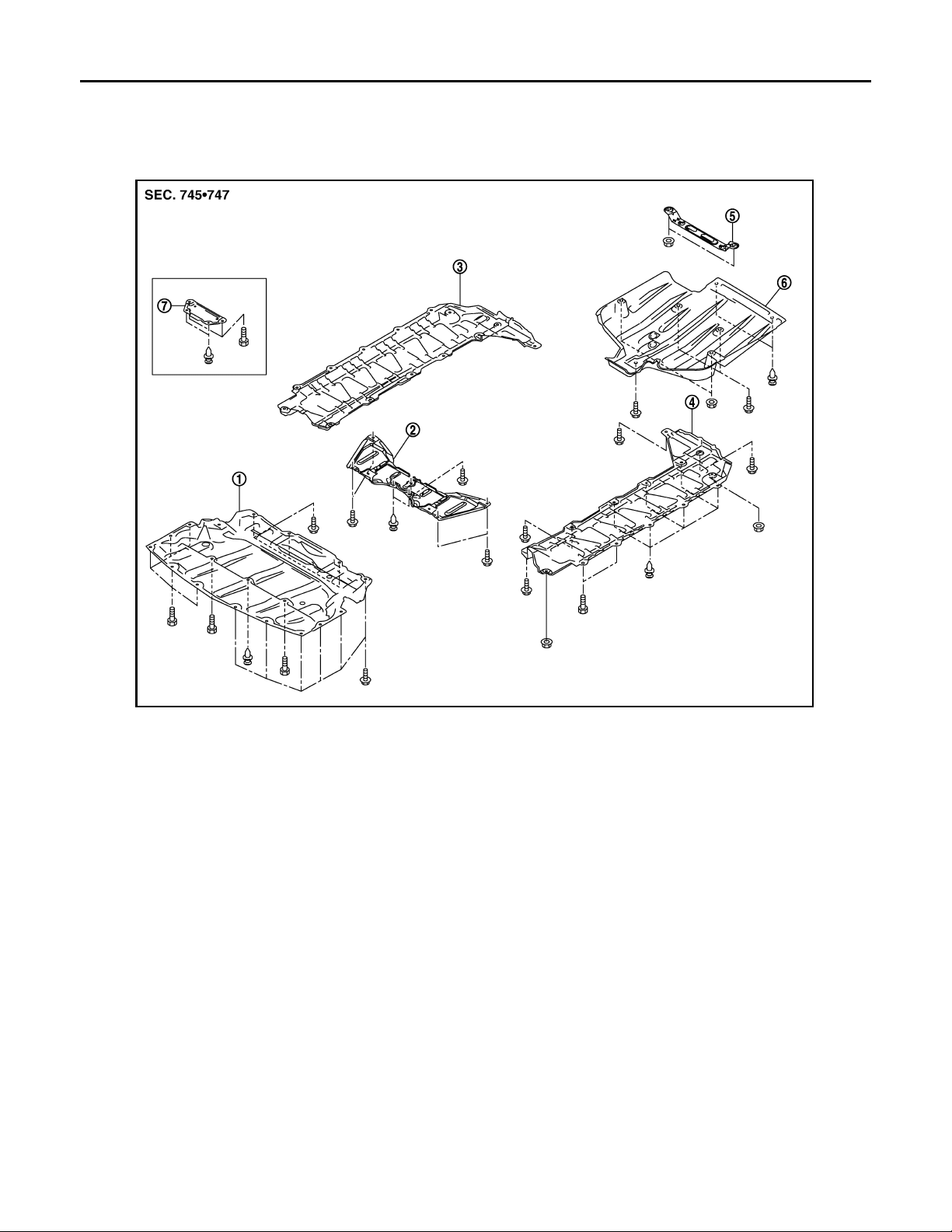
FLOOR SIDE FAIRING
B
Revision: October 2006
2007 G35 Sedan
< ON-VEHICLE REPAIR >
FLOOR SIDE FAIRING
Exploded View INFOID:0000000000961806
JMKIA0081G
1. Engine lower cover 2. Front under cover (4WD models) 3. Floor under cover (RH)
4. Floor under cover (LH) 5. Rear diffuser bracket 6. Rear diffuser
7. Front under cover (2WD models)
Removal and Installation INFOID:0000000000961807
REMOVAL
ENGINE LOWER COVER
1. Remove engine lower cover mounting clip.
2. Remove engine lower cover mounting bolts with power tool.
3. Remove front under cover.
FLOOR UNDER COVER (LH/RH)
1. Remove floor under cover mounting clips.
2. Remove floor under cover mounting bolts and nuts with power tool.
3. Remove floor under cover.
REAR DIFFUSER
1. Remove rear diffuser mounting clips.
2. Remove rear diffuser mounting bolts and nuts with power tool.
3. Remove rear diffuser.
INSTALLATION
EXT-26
Page 27

< ON-VEHICLE REPAIR >
Revision: October 2006
2007 G35 Sedan
Install in the reverse order of removal.
FLOOR SIDE FAIRING
A
B
C
D
E
F
G
H
I
J
EXT
L
M
N
O
P
EXT-27
Page 28
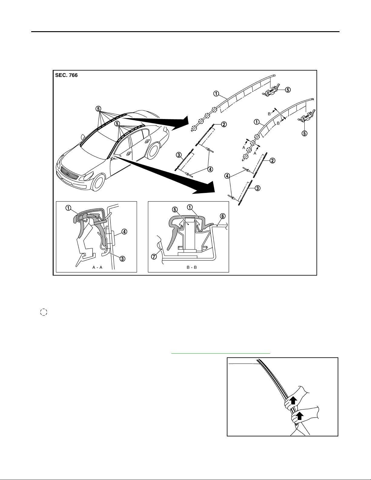
ROOF SIDE MOLDING
B
Revision: October 2006
2007 G35 Sedan
< ON-VEHICLE REPAIR >
ROOF SIDE MOLDING
Exploded View INFOID:0000000000961808
JMKIA0082G
1. Roof side molding 2. Molding fastener (upper) 3. Molding fastener (lower)
4. Rivet 5. Roof side molding clip 6. Body side p anel
7. Roof panel
Clip
Removal and Installation INFOID:0000000000961809
REMOVAL
1. Remove front fender cover (LH/RH). Refer to EXT-18, "Removal and Installation".
2. Disengage clips while pinching molding from roof rear end to
front end.
PIIB2749J
INSTALLATION
Install from roof side molding rear end to front end in this order after temporarily holding.
EXT-28
Page 29

ROOF SIDE MOLDING
Revision: October 2006
2007 G35 Sedan
< ON-VEHICLE REPAIR >
REMOVAL AND INSTALLATION OF ROOF SIDE MOLDING CLIP
Removal
1. Remove roof side molding.
2. Heat adhesive tape interface using a dryer, and then peel roof side molding clips (body side) using longnose pliers.
CAUTION:
Be careful not to damage the body.
Installation
1. Clean tape removed surface with a shop cloth soaked in white gasoline or IPA.
2. Use two-part epoxy adhesive.
Adhesive : 3M-weld DP–100 or equivalent
3. Apply adhesive evenly to clip tape surface.
A
B
C
D
E
Thickness : Approximately 0.5 mm (0.020 in)
4. Position applied parts to the proper location, and then sufficiently press-fit until the adhesive protrudes to
tape side.
Press-fit limit : 19.6 N·× 2 seconds×
5. Tape clips after press fit, and temporarily hold it for specified time based on the following.
5 to 10 °C (41 to 50 °F) : 1 hour or more
11 to 23 °C (52 to 73 °F) : 30 minutes or more
24 °C or more (75 °F or more) : 15 minutes or more
6. Install from roof side molding rear end to front end in this order after temporarily holding.
CAUTION:
• Use double-faced adhesive tape after hardening for clips.
• Securely insert molding rear end cap onto roof rear end cutout (installation standard).
• When installing roof side molding of windshield portion, check that molding fastener is securely
inserted and then press in.
• Do not wash the vehicle with in 24 hours so as to keep adhesive.
F
G
H
I
J
EXT
L
M
N
O
P
EXT-29
Page 30
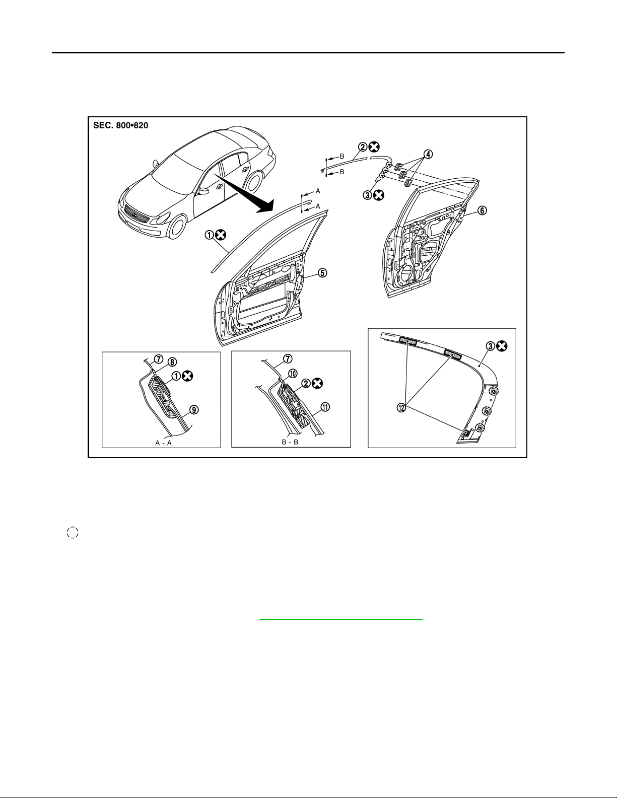
DOOR SASH MOLDING
B
Revision: October 2006
2007 G35 Sedan
< ON-VEHICLE REPAIR >
DOOR SASH MOLDING
Exploded View INFOID:0000000000961810
JMKIA0083G
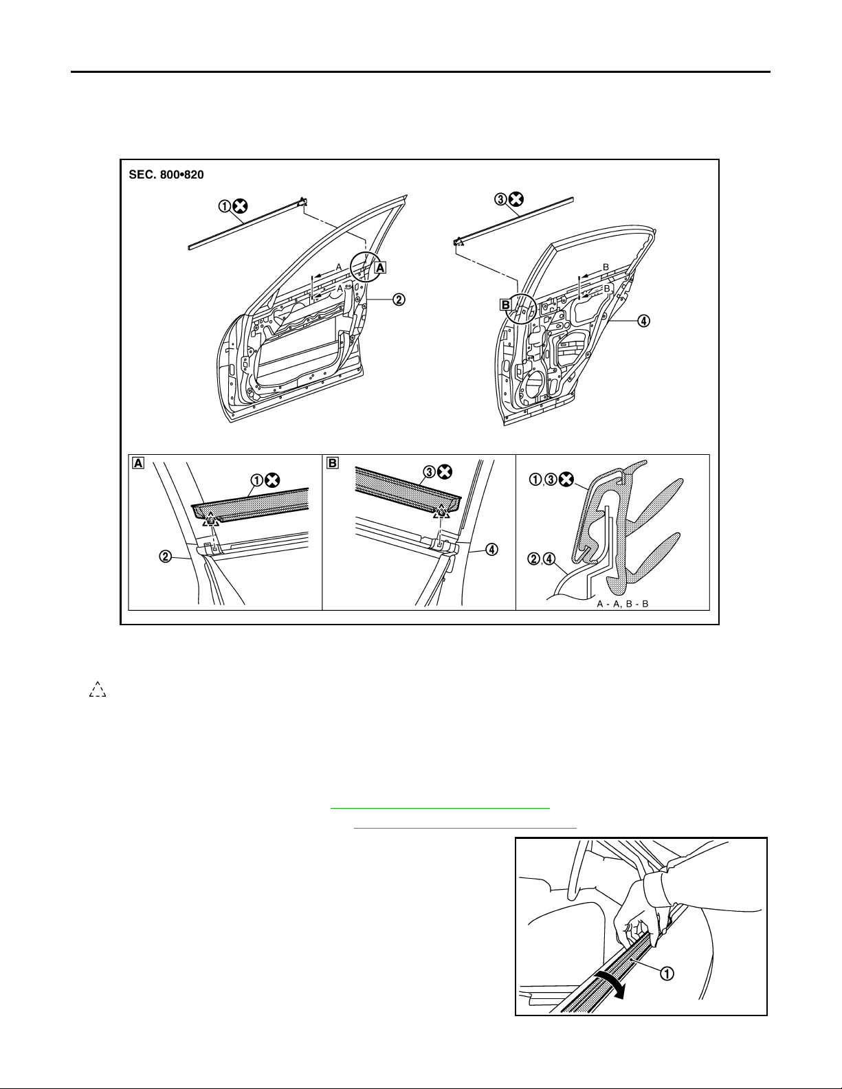
1. Front door sash molding 2. Rear door sash molding (front) 3. Rear door sash molding (rear)
4. Molding clip 5. Front door panel 6. Rear door panel
7. Body side outer panel 8. Front door weather strip 9. Front door sash
10. Rear door weather strip 11. Rear door sash 12. Double-faced adhesive tape
Clip
Removal and Installation INFOID:0000000000961811
FRONT DOOR SASH MOLDING
Removal
1. Remove door mirror assembly . Refer to MIR-67, "Removal and Installation".
2. Remove front door weather strip.
3. Release roof portion of glass run.
EXT-30
Page 31
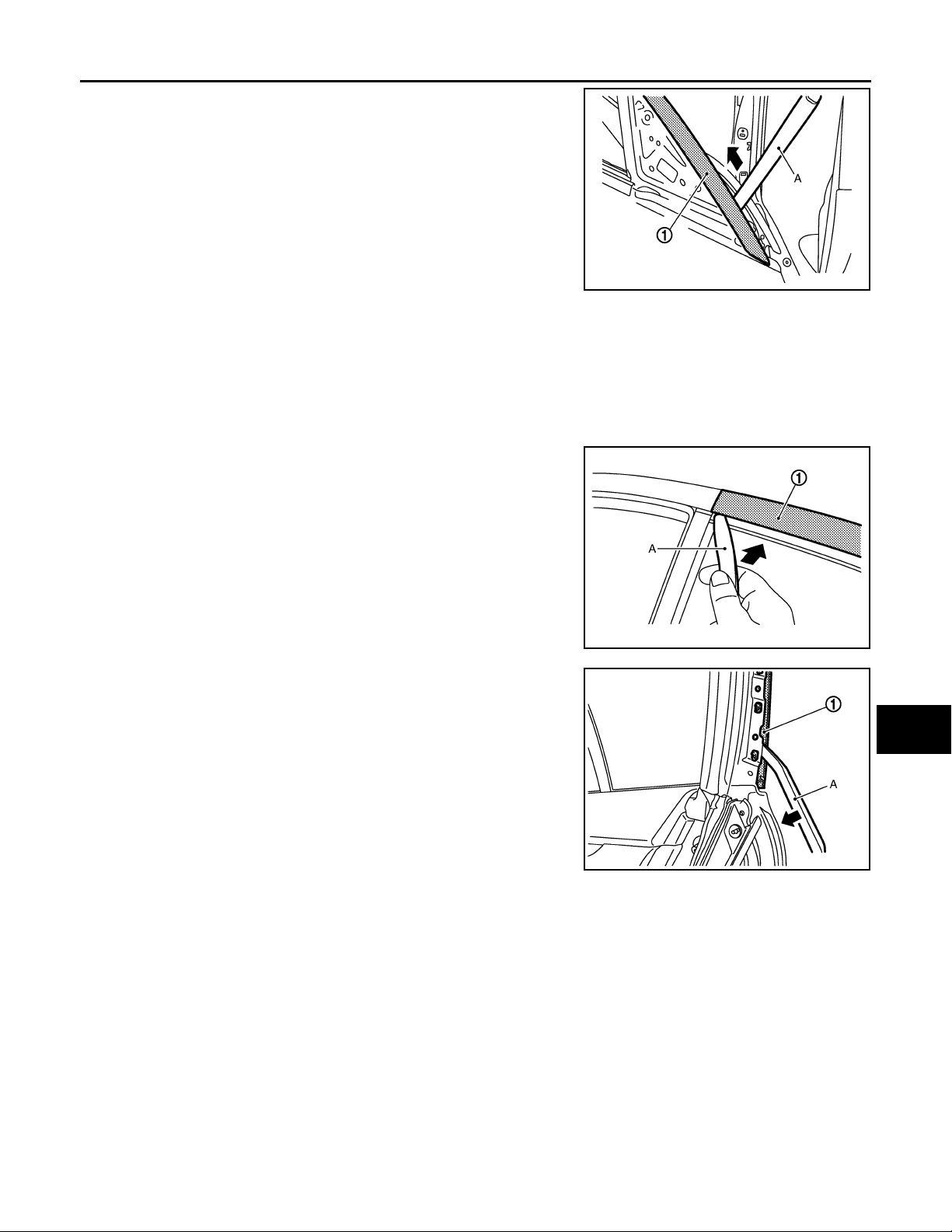
DOOR SASH MOLDING
Revision: October 2006
2007 G35 Sedan
< ON-VEHICLE REPAIR >
4. Remove front door sash molding (1) connection between door
panel and molding from glass run side, using a remover tool (A).
5. Remove front door sash molding (1).
Installation
Install in the reverse order of removal.
A
B
C
JMKIA0113GB
D
REAR DOOR SUSH MOLDING
Removal
1. Remove rear door weather strip.
2. Release roof portion of glass run.
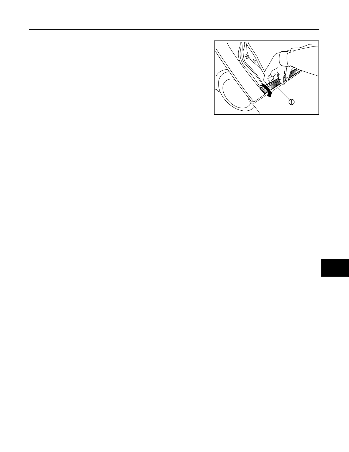
3. Remove rear door sash molding (1) connection between door
panel and molding from glass run side, using a remover tool (A).
4. Remove rear door sash molding (front) (1).
5. Release rear door sash molding connection between rear door
panel and molding (1), using a remover tool (A), and take off
double-faced adhesive tape.
6. Remove rear door sash molding (rear) (1).
E
F
G
H
I
JMKIA0114GB
J
EXT
L
Installation
Install in the reverse order of removal.
CAUTION:
• l Do not let air between contact surfaces when installing.
• l To secure contact, do not wash vehicle within 24 hours after installation.
• Do not use a material for remover tool (A) which could damage door panel.
EXT-31
JMKIA0115GB
M
N
O
P
Page 32
DOOR OUTSIDE MOLDING
B
Revision: October 2006
2007 G35 Sedan
< ON-VEHICLE REPAIR >
DOOR OUTSIDE MOLDING
Exploded View INFOID:0000000000961812
JMKIA0084G
1. Front door outside molding 2. Front door panel 3. Rear door outside molding
4. Rear door panel
Pawl
Removal and Installation INFOID:0000000000961813
REMOVAL
FRONT DOOR OUTSIDE MOLDING
1. Remove front door finisher. Refer to INT-10, "Removal and Installation".
2. Remove door mirror assembly . Refer to MIR-67, "
3. Twists and pull up to upper side, and then remove front door outside molding (1).
Removal and Installation".
JMKIA0116GB
REAR DOOR OUTSIDE MOLDING
EXT-32
Page 33
DOOR OUTSIDE MOLDING
Revision: October 2006
2007 G35 Sedan
< ON-VEHICLE REPAIR >
1. Remove rear door finisher. Refer to INT-10, "Removal and Installation".
2. Twist s and pull up to upper side, and then remove rear door outside molding (1).
A
B
C
INSTALLATION
Install in the reverse order of removal.
JMKIA0117GB
D
E
F
G
H
I
J
EXT
L
M
N
O
P
EXT-33
Page 34
DOOR PARTING SEAL
B
Revision: October 2006
2007 G35 Sedan
< ON-VEHICLE REPAIR >
DOOR PARTING SEAL
Exploded View INFOID:0000000000961814
JMKIA0085G
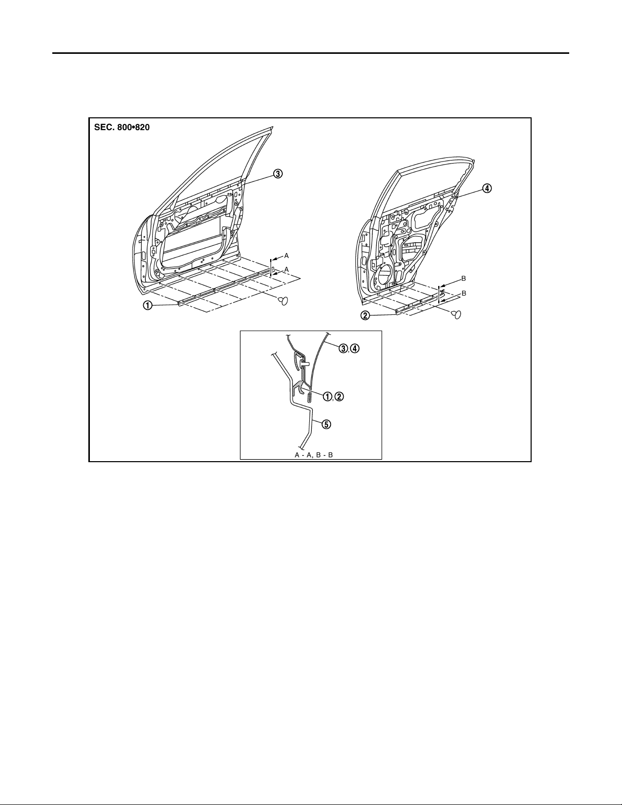
1. Front door p arting seal 2. Rear door p arting seal 3. Front door panel
4. Rear door panel 5. Center mud guard
Removal and Installation INFOID:0000000000961815
REMOVAL
FRONT DOOR PARTING SEAL
1. Fully open front door.
2. Remove front door parting seal mounting plastic clips.
3. Remove front door parting seal.
REAR DOOR PARTING SEAL
1. Fully open rear door.
2. Remove rear door parting seal mounting plastic clips.
3. Remove rear door parting seal.
INSTALLATION
Install in the reverse order of removal.
EXT-34
Page 35
< ON-VEHICLE REPAIR >
B
Revision: October 2006
2007 G35 Sedan
TRUNK LID FINISHER
TRUNK LID FINISHER
Exploded View INFOID:0000000000961816
A
B
C
D
E
F
G
H
JMKIA0086G
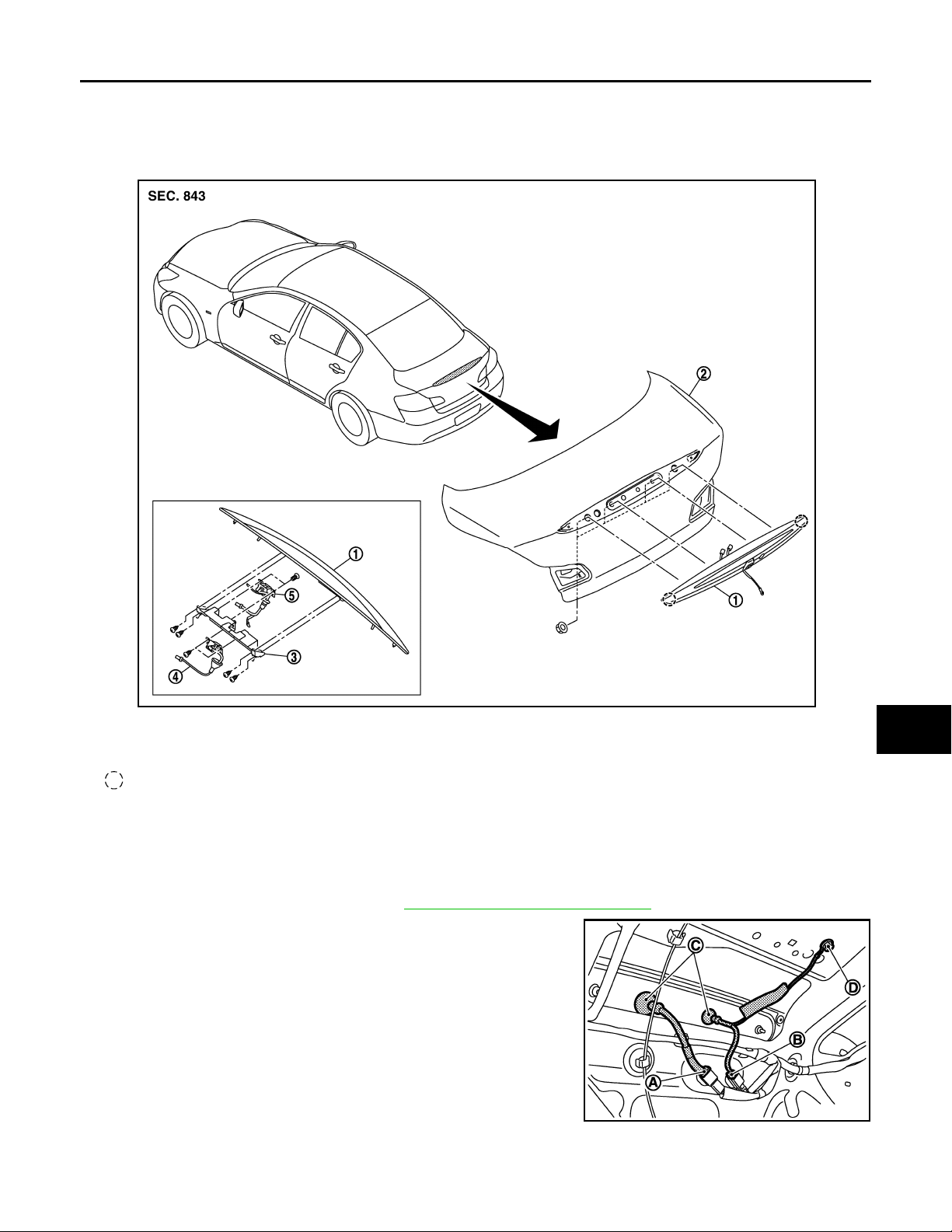
1. Trunk lid finisher outer 2. Trunk lid panel 3. Inner bracket
4. Rear view camera assembly 5. Trunk opener switch assembly
Clip
Removal and Installation INFOID:0000000000961817
REMOVAL
1. Fully open trunk lid.
2. Remove trunk lid finisher inner. Refer to INT-27, "
3. Disconnect rear view camera harness connector (A) and trunk
opener request switch harness connector (B).
4. Remove harness grommet (C).
5. Remove bolt (D).
Removal and Installation".
I
J
EXT
L
M
N
O
P
JMKIA0118GB
EXT-35
Page 36
TRUNK LID FINISHER
B
Revision: October 2006
2007 G35 Sedan
< ON-VEHICLE REPAIR >
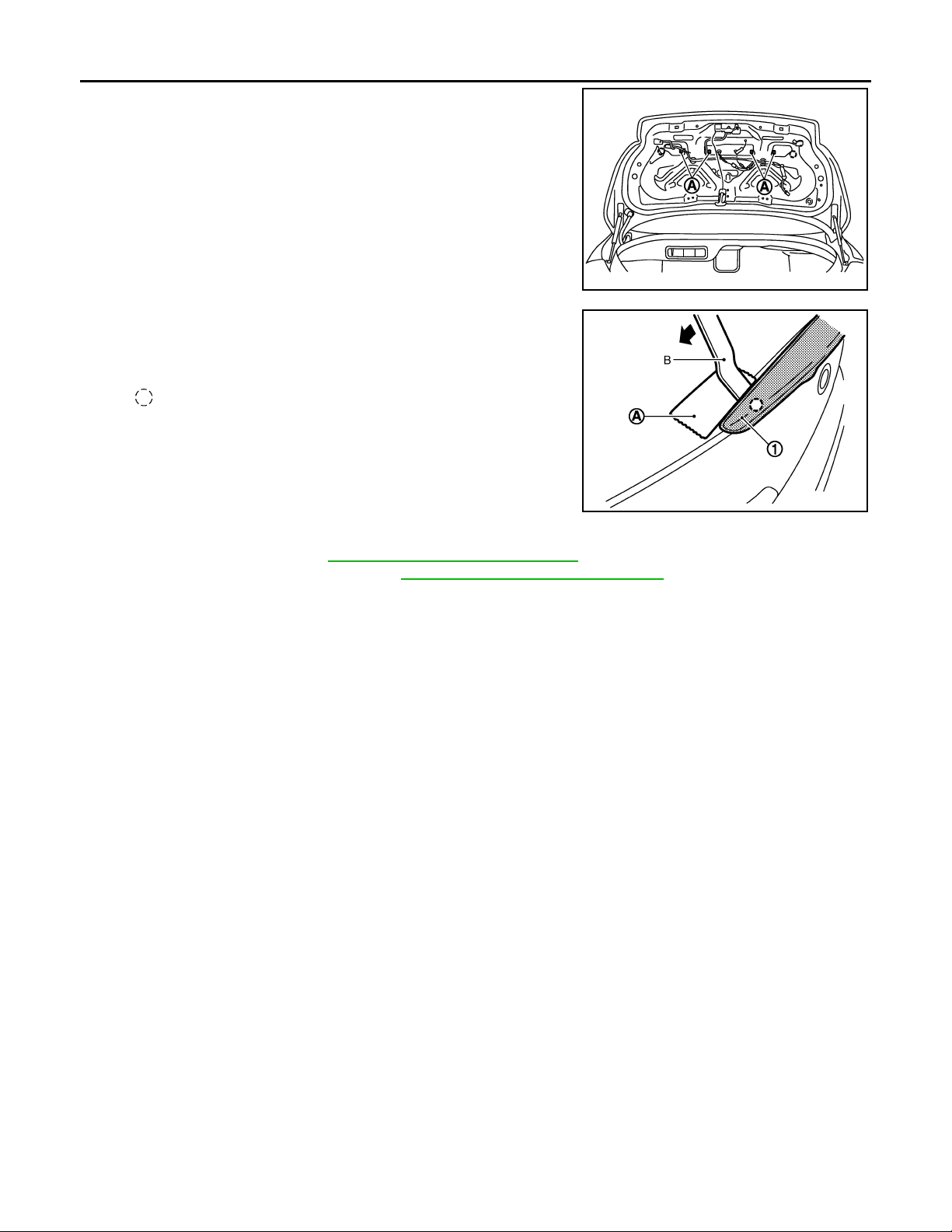
6. Remove trunk lid finisher outer mounting nuts (A).
7. Apply protection tape (A) around outer circumference of trunk lid
finisher outer (1).
8. Remove trunk lid finisher outer (1), using remover tool (B).
: Clip
CAUTION:
Be careful not to damage the body.
JMKIA0119GB
9. Remove the following parts after removing trunk lid finisher outer.
• Rear view camera. Refer to AV-550, "
• Trunk opener request switch. Refer to DLK-224, "
Removal and Installation".
Removal and Installation".
INSTALLATION
Install in the reverse order of removal.
CAUTION:
Install after cleaning adhesive parts of body side and back of finisher outer.
JMKIA0120G
EXT-36
Page 37
< ON-VEHICLE REPAIR >
B
B
Revision: October 2006
2007 G35 Sedan
REAR SPOILER
REAR SPOILER
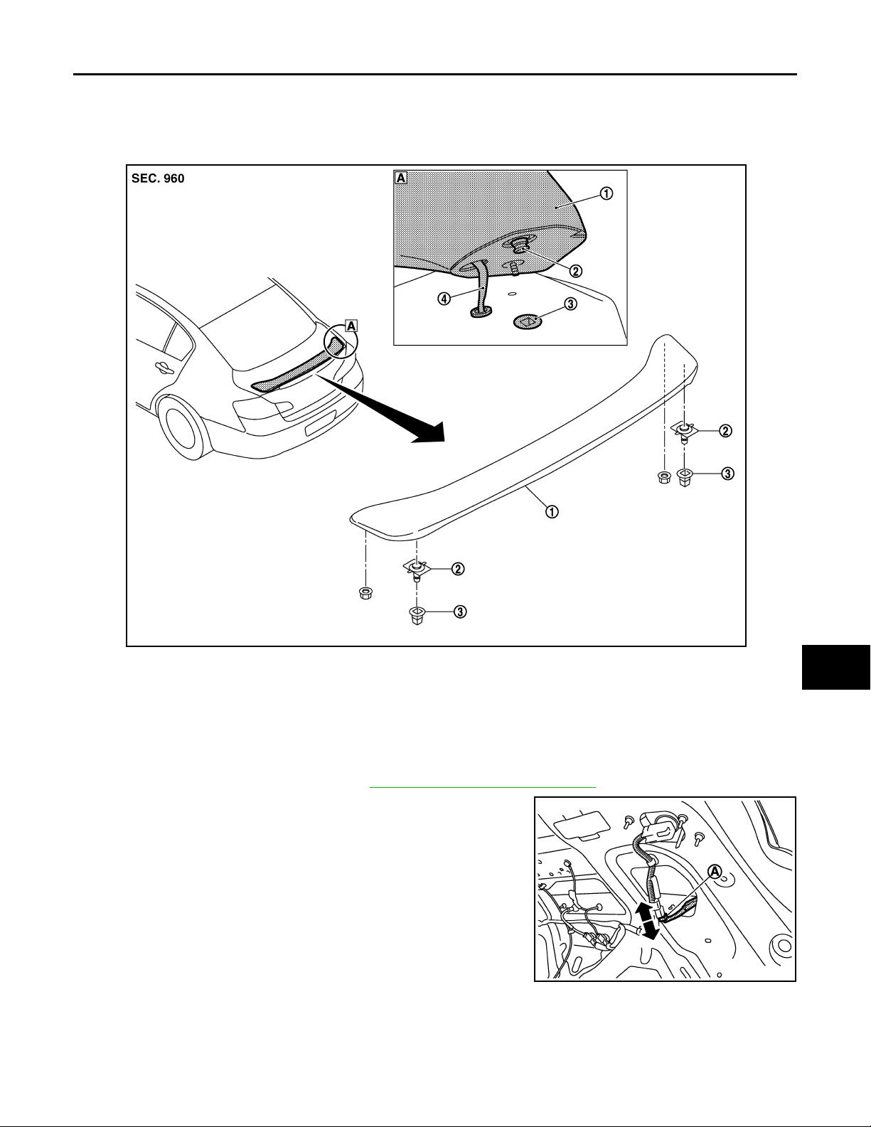
Exploded View INFOID:0000000000961818
A
B
C
D
E
F
G
H
JMKIA0087G
1. Rear spoiler 2. Rear spoiler clip 3. Grommet
4. High-mou nte d stop lam p ha rne ss
Removal and Installation INFOID:0000000000961819
REMOVAL
1. Remove trunk lid finisher inner. Refer to INT-27, "Removal and Installation".
2. Disconnect harness connector (A) of high-mounted stop lamp.
JMKIA0121G
I
J
EXT
L
M
N
O
P
EXT-37
Page 38
REAR SPOILER
B
B
Revision: October 2006
2007 G35 Sedan
< ON-VEHICLE REPAIR >
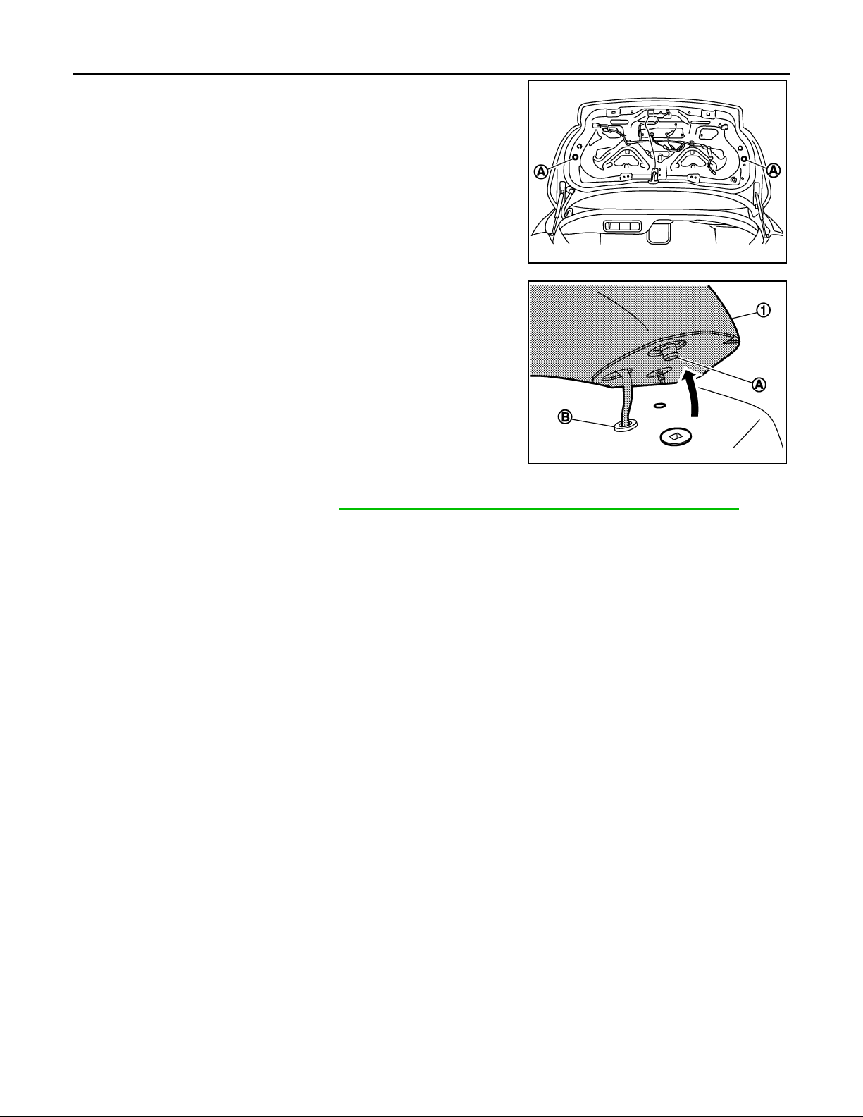
3. Remove rear spoiler mounting nuts (A).
4. Disengage rear spoiler mounting clip (A) then disconnect grommet (B) of high-mounted stop lamp harness.
5. Remove rear spoiler (1).
JMKIA0122G
6. Remove following parts after removing rear spoiler.
• High-mounted stop lamp. Refer to EXL-199, "
WITH REAR SPOILER : Removal and Installation".
• Rear spoiler clip and grommet.
INSTALLATION
Install in the reverse order of removal.
CAUTION:
Be careful not to damage the body.
JMKIA0123G
EXT-38
 Loading...