

Page 1

DRIVER CONTROLS
Revision: 2007 November 2008 EX35
A
B
SECTION EXL
EXTERIOR LIGHTING SYSTEM
CONTENTS
XENON TYPE
BASIC INSPECTION ....................................7
DIAGNOSIS AND REPAIR WORKFLOW ..........7
Work Flow .................................................................7
INSPECTION AND ADJUSTMENT ..................... 9
ADDITIONAL SERVICE WHEN REPLACING
CONTROL UNIT (AFS CONTROL UNIT) ...................
ADDITIONAL SERVICE WHEN REPLACING
CONTROL UNIT (AFS CONTROL UNIT) : De-
scription ........................... ..........................................
ADDITIONAL SERVICE WHEN REPLACING
CONTROL UNIT (AFS CONTROL UNIT) : Special
Repair Requirement ..................................................
ADDITIONAL SERVICE WHEN REPLACING
CONTROL UNIT (HEIGHT SENSOR) .........................
ADDITIONAL SERVICE WHEN REPLACING
CONTROL UNIT (HEIGHT SENSOR) : Descrip-
tion ............................................................................
ADDITIONAL SERVICE WHEN REPLACING
CONTROL UNIT (HEIGHT SENSOR) : Special
Repair Requirement ..................................................
LEVELIZER ADJUSTMENT ........................................9
LEVELIZER ADJUSTMENT : Description .................9
LEVELIZER ADJUSTMENT : Special Repair Re-
quirement ..................................................................
FUNCTION DIAGNOSIS ..............................11
HEADLAMP SYSTEM ........................................11
System Diagram ......................................................11
System Description .................................................11
Component Parts Location ......................................12
Component Description ......................... .................13
AUTO LIGHT SYSTEM ......................................14
System Diagram ......................................................14
System Description .................................................14
Component Parts Location ......................................15
Component Description ..........................................16
DAYTIME RUNNING LIGHT SYSTEM .............17
System Diagram ......................................................17
System Description ..................................................17
Component Parts Location ......................................18
Component Description ..........................................18
ACTIVE ADAPTIVE FRONT-LIGHTING SYS-
9
TEM ...................................................................
System Diagram ......................................................20
9
9
9
9
System Description ..................................................20
Component Parts Location ......................................22
Component Description ...........................................22
FRONT FOG LAMP SYSTEM ...........................24
System Diagram ......................................................24
System Description ..................................................24
Component Parts Location ......................................25
Component Description ..........................................25
TURN SIGNAL AND HAZARD WARNING
LAMP SYSTEM .................................................
9
9
System Diagram ......................................................26
System Description ..................................................26
Component Parts Location ......................................27
Component Description ..........................................27
PARKING, LICENSE PLATE AND TAIL
LAMPS SYSTEM ..............................................
System Diagram ......................................................28
System Description ..................................................28
Component Parts Location ......................................29
Component Description ..........................................29
EXTERIOR LAMP BATTERY SAVER SYS-
TEM ...................................................................
System Diagram ......................................................30
System Description ..................................................30
Component Parts Location ......................................31
Component Description ..........................................31
20
26
28
30
C
D
E
F
G
H
I
J
K
EXL
M
N
O
P
EXL-1
Page 2

DIAGNOSIS SYSTEM (BCM) ............................ 32
Revision: 2007 November 2008 EX35
COMMON ITEM . ... .... ................................................ 32
COMMON ITEM : CONSULT-III Function (BCM -
COMMON ITEM) ....................................................
HEADLAMP .............................................................. 33
HEADLAMP : CONSULT-III Function (BCM -
HEAD LAMP) ..........................................................
FLASHER .............................. .................................... 35
FLASHER : CONSULT-III Function (BCM -
FLASHER) .......................... ....................................
32
33
35
DIAGNOSIS SYSTEM (IPDM E/R) ....................37
Diagnosis Description ............................................. 37
CONSULT-III Function (IPDM E/R) ........................ 39
DIAGNOSIS SYSTEM (AFS) ............................. 42
CONSULT-III Function (ADAPTIVE LIGHT) ........... 42
COMPONENT DIAGNOSIS ........................ 44
B2503, B2504 SWIVEL ACTUATOR ................ 44
Description ....................... .......................... ............. 44
DTC Logic ............................................................... 44
Diagnosis Procedure .............................................. 45
Component Inspection ............................................ 48
B2514 HEIGHT SENSOR UNUSUAL [RR] ....... 50
Description ....................... .......................... ............. 50
DTC Logic ............................................................... 50
Diagnosis Procedure .............................................. 50
Component Inspection ............................................ 52
B2516 SHIFT SIGNAL [P, R] ............................ 53
Description ....................... .......................... ............. 53
DTC Logic ............................................................... 53
Diagnosis Procedure .............................................. 53
B2517 VEHICLE SPEED SIGNAL .................... 54
Description ....................... .......................... ............. 54
DTC Logic ............................................................... 54
Diagnosis Procedure .............................................. 54
Description ..............................................................60
DTC Logic ................. .... ... ... ....................................60
Diagnosis Procedure ..... ... .......................................60
U1000 CAN COMM CIRCUIT ............................ 61
Description ..............................................................61
DTC Logic ................. .... ... ... ....................................61
Diagnosis Procedure ..... ... .......................................61
U1010 CONTROL UNIT (CAN) ......................... 62
DTC Logic ................. .... ... ... ....................................62
Diagnosis Procedure ..... ... .......................................62
POWER SUPPLY AND GROUND CIRCUIT ..... 63
BCM (BODY CONTROL MODULE) ..........................63
BCM (BODY CONTROL MODULE) : Diagnosis
Procedure ...............................................................
IPDM E/R (INTELLIGENT POWER DISTRIBU-
TION MODULE ENGINE ROOM) ..............................
IPDM E/R (INTELLIGENT POWER DISTRIBUTION MODULE ENGINE ROOM) : Diagnosis Pro-
cedure .....................................................................
AFS CONTROL UNIT ................................................ 64
AFS CONTROL UNIT : Diagnosis Procedure .........64
63
63
63
EXTERIOR LAMP FUSE ................................... 66
Description ..............................................................66
Diagnosis Procedure ..... ... .......................................66
HEADLAMP (HI) CIRCUIT ................................ 67
Component Function Check ................................... 67
Diagnosis Procedure ..... ... .......................................67
HEADLAMP (LO) CIRCUIT ............................... 69
Description ..............................................................69
Component Function Check ................................... 69
Diagnosis Procedure ..... ... .......................................69
XENON HEADLAMP ......................................... 71
Description ..............................................................71
Diagnosis Procedure ..... ... .......................................71
B2519 LEVELIZER CALIBRATION ..................55
Description ....................... .......................... ............. 55
DTC Logic ............................................................... 55
Diagnosis Procedure .............................................. 55
B2521 ECU CIRCUIT .........................................56
Description ....................... .......................... ............. 56
DTC Logic ............................................................... 56
Diagnosis Procedure .............................................. 56
C0126 STEERING ANGLE SENSOR SIGNAL ...59
Description ....................... .......................... ............. 59
DTC Logic ............................................................... 59
Diagnosis Procedure .............................................. 59
C0428 STEERING ANGLE SENSOR CALI-
BRATION ...........................................................
HEADLAMP LEVELIZER CIRCUIT .................. 73
Description ..............................................................73
Component Function Check ................................... 73
Diagnosis Procedure ..... ... .......................................73
FRONT FOG LAMP CIRCUIT ........................... 75
Component Function Check ................................... 75
Diagnosis Procedure ..... ... .......................................75
PARKING LAMP CIRCUIT ................................ 77
Component Function Check ................................... 77
Diagnosis Procedure ..... ... .......................................77
TURN SIGNAL LAMP CIRCUIT ........................ 79
Description ..............................................................79
Component Function Check ................................... 79
60
Diagnosis Procedure ..... ... .......................................79
EXL-2
Page 3

OPTICAL SENSOR ............................................81
Revision: 2007 November 2008 EX35
Description ..............................................................81
Component Function Check ....................................81
Diagnosis Procedure ................................. ..............81
HAZARD SWITCH ..............................................84
Description ..............................................................84
Component Function Check ....................................84
Diagnosis Procedure ................................. ..............84
TAIL LAMP CIRCUIT .........................................86
Component Function Check ....................................86
Diagnosis Procedure ................................. ..............86
LICENSE PLATE LAMP CIRCUIT .....................88
Component Function Check ....................................88
Diagnosis Procedure ................................. ..............88
HEADLAMP SYSTEM ........................................89
Wiring Diagram - HEADLAMP - ..............................89
AUTO LIGHT SYSTEM ......................................93
Wiring Diagram - AUTO LIGHT SYSTEM - .............93
DAYTIME RUNNING LIGHT SYSTEM ..............97
Wiring Diagram - DAYTIME LIGHT SYSTEM - .......97
FRONT FOG LAMP SYSTEM ..........................101
Wiring Diagram - FRONT FOG LAMP - ................101
TURN SIGNAL AND HAZARD WARNING
LAMP SYSTEM ................................................
Wiring Diagram - TURN AND HAZARD WARN-
ING LAMPS - ............................... ... .... ... ... ... .........
104
104
PARKING, LICENSE PLATE AND TAIL
LAMPS SYSTEM ..............................................
Wiring Diagram - PARKING, LICENSE PLATE
AND TAIL LAMPS - ...............................................
108
108
STOP LAMP .....................................................113
Wiring Diagram - STOP LAMP - ...........................113
BACK-UP LAMP ..............................................116
Wiring Diagram - BACK-UP LAMP - .....................116
ECU DIAGNOSIS ....................................... 119
BCM (BODY CONTROL MODULE) .................119
Reference Value ...................................................119
Wiring Diagram - BCM - ........................................143
Fail-safe ................................................................149
DTC Inspection Priority Chart .............................151
DTC Index ............................................................ 153
IPDM E/R (INTELLIGENT POWER DISTRI-
BUTION MODULE ENGINE ROOM) ...............
Reference Value ...................................................155
Wiring Diagram - IPDM E/R - ................................162
Fail-safe ................................................................165
DTC Index ............................................................ 167
155
AFS CONTROL UNIT .....................................168
Reference Value ....................................................168
Wiring Diagram - ACTIVE AFS - ...........................171
Fail-Safe ................................................................177
DTC Inspection Priority Chart ................................177
DTC Index .............................................................178
SYMPTOM DIAGNOSIS ............................ 179
EXTERIOR LIGHTING SYSTEM SYMPTOMS .179
Symptom Table .....................................................179
NORMAL OPERATING CONDITION .............181
Description ....................... ......................................181
BOTH SIDE HEADLAMPS (HI) ARE NOT
TURNED ON ...................................................
Description ....................... ......................................182
Diagnosis Procedure .............................................182
182
BOTH SIDE HEADLAMPS (LO) ARE NOT
TURNED ON ...................................................
Description ....................... ......................................183
Diagnosis Procedure .............................................183
183
PARKING, LICENSE PLATE AND TAIL
LAMPS ARE NOT TURNED ON .....................
Description ....................... ......................................184
Diagnosis Procedure .............................................184
184
BOTH SIDE FRONT FOG LAMPS ARE NOT
TURNED ON ...................................................
Description ....................... ......................................185
Diagnosis Procedure .............................................185
185
PRECAUTION ............................................ 186
PRECAUTIONS ...............................................186
Precaution for Supplemental Restrain t Syste m
(SRS) "AIR BAG" and "SEAT BELT PRE-TEN-
SIONER" ...............................................................
Precautions For Xenon Headlamp Service ...........186
186
ON-VEHICLE MAINTENANCE .................. 187
HEADLAMP AIMING ADJUSTMENT .............187
Description ....................... ......................................187
Aiming Adjustment Procedure ...............................188
FRONT FOG LAMP AIMING ADJUSTMENT .190
Description ....................... ......................................190
Aiming Adjustment Procedure ...............................190
ON-VEHICLE REPAIR ............................... 192
FRONT COMBINATION LAMP ......................192
Exploded View .......................................................192
Removal and Installation .......................................193
Replacement .........................................................193
Disassembly and Assembly ...................................194
FRONT FOG LAMP ........................................195
A
B
C
D
E
F
G
H
I
J
K
EXL
M
N
O
P
EXL-3
Page 4

Exploded View .............................. ... .... ... ... ............ 195
Revision: 2007 November 2008 EX35
Removal and Installation .......................................195
Replacement .........................................................195
OPTICAL SENSOR ......................................... 197
Exploded View .............................. ... .... ... ... ............ 197
Removal and Installation .......................................197
LIGHTING AND TURN SIGNAL SWITCH ....... 198
Exploded View .............................. ... .... ... ... ............ 198
DIAGNOSIS AND REPAIR WORKFLOW ........210
Work Flow ............................................................. 210
FUNCTION DIAGNOSIS ...........................212
HEADLAMP SYSTEM ......................................212
System Diagram ........................... ... ... ... .... ........... 212
System Description ............................................... 212
Component Parts Location ...................................213
Component Description ......................... ............... 214
HAZARD SWITCH ........................................... 199
Exploded View .............................. ... .... ... ... ............ 199
AFS CONTROL UNIT ...................................... 200
Exploded View .............................. ... .... ... ... ............ 200
Removal and Installation .......................................200
STEERING ANGLE SENSOR ......................... 201
Removal and Installation .......................................201
AFS OFF SWITCH ........................................... 202
Exploded View .............................. ... .... ... ... ............ 202
Removal and Installation .......................................202
HEIGHT SENSOR ............................................ 203
Exploded View .............................. ... .... ... ... ............ 203
Removal and Installation .......................................203
REAR COMBINATION LAMP ......................... 204
Exploded View .............................. ... .... ... ... ............ 204
Removal and Installation .......................................204
REAR TURN SIGNAL LAMP .......................... 205
Exploded View .............................. ... .... ... ... ............ 205
Removal and Installation .......................................205
Replacement .........................................................205
HIGH-MOUNTED STOP LAMP ....................... 206
Exploded View .............................. ... .... ... ... ............ 206
Removal and Installation .......................................206
BACK-UP LAMP .............................................. 207
Exploded View .............................. ... .... ... ... ............ 207
Removal and Installation .......................................207
Replacement .........................................................207
LICENSE PLATE LAMP .................................. 208
Exploded View .............................. ... .... ... ... ............ 208
Removal and Installation .......................................208
Replacement .........................................................208
SERVICE DATA AND SPECIFICATIONS
(SDS) ..........................................................
SERVICE DATA AND SPECIFICATIONS
(SDS) ................................................................
Bulb Specifications ................................................209
209
209
HALOGEN TYPE
BASIC INSPECTION ..................................
210
AUTO LIGHT SYSTEM ....................................215
System Diagram ........................... ... ... ... .... ........... 215
System Description ............................................... 215
Component Parts Location ...................................216
Component Description ......................... ............... 217
DAYTIME RUNNING LIGHT SYSTEM ............. 218
System Diagram ........................... ... ... ... .... ........... 218
System Description ............................................... 218
Component Parts Location ...................................219
Component Description ......................... ............... 219
FRONT FOG LAMP SYSTEM ..........................221
System Diagram ........................... ... ... ... .... ........... 221
System Description ............................................... 221
Component Parts Location ...................................222
Component Description ......................... ............... 222
TURN SIGNAL AND HAZARD WARNING
LAMP SYSTEM ................................................
System Diagram ........................... ... ... ... .... ........... 223
System Description ............................................... 223
Component Parts Location ...................................224
Component Description ......................... ............... 224
223
PARKING, LICENSE PLATE AND TAIL
LAMPS SYSTEM ..............................................
System Diagram ........................... ... ... ... .... ........... 225
System Description ............................................... 225
Component Parts Location ...................................226
Component Description ......................... ............... 226
225
EXTERIOR LAMP BATTERY SAVER SYS-
TEM ...................................................................
System Diagram ........................... ... ... ... .... ........... 227
System Description ............................................... 227
Component Parts Location ...................................228
Component Description ......................... ............... 228
227
DIAGNOSIS SYSTEM (BCM) ...........................229
COMMON ITEM ....................................................... 229
COMMON ITEM : CONSULT-III Function (BCM -
COMMON ITEM) ............................. ... ... .... ...........
HEADLAMP ........................... .......................... ........ 230
HEADLAMP : CONSULT-III Function (BCM -
HEAD LAMP) ........................................................
FLASHER ................................................................ 232
229
230
EXL-4
Page 5

FLASHER : CONSULT-III Function (BCM -
Revision: 2007 November 2008 EX35
FLASHER) ............................................................
232
HEADLAMP SYSTEM .....................................260
Wiring Diagram - HEADLAMP - .............................260
A
DIAGNOSIS SYSTEM (IPDM E/R) ...................234
Diagnosis Description .................. ... .... ... ... ............234
CONSULT-III Function (IPDM E/R) .......................236
COMPONENT DIAGNOSIS ....................... 239
POWER SUPPLY AND GROUND CIRCUIT ....239
BCM (BODY CONTROL MODULE) ........................ 239
BCM (BODY CONTROL MODULE) : Diagnosis
Procedure ..................... ................ ................ .........
IPDM E/R (INTELLIGENT POWER DISTRIBU-
TION MODULE ENGINE ROOM) ............................
IPDM E/R (INTELLIGENT POWER DISTRIBUTION MODULE ENGINE ROOM) : Diagnosis Pro-
cedure ...................................................................
EXTERIOR LAMP FUSE ..................................241
Description ............................................................241
Diagnosis Procedure ................................. ............241
HEADLAMP (HI) CIRCUIT ...............................242
Component Function Check ..................................242
Diagnosis Procedure ................................. ............242
HEADLAMP (LO) CIRCUIT ..............................244
Component Function Check ..................................244
Diagnosis Procedure ................................. ............244
FRONT FOG LAMP CIRCUIT ..........................246
Component Function Check ..................................246
Diagnosis Procedure ................................. ............246
PARKING LAMP CIRCUIT ...............................248
Component Function Check ..................................248
Diagnosis Procedure ................................. ............248
TURN SIGNAL LAMP CIRCUIT .......................250
Description ............................................................250
Component Function Check ..................................250
Diagnosis Procedure ................................. ............250
OPTICAL SENSOR ..........................................252
Description ............................................................252
Component Function Check ..................................252
Diagnosis Procedure ................................. ............252
HAZARD SWITCH ............................................255
Description ............................................................255
Component Function Check ..................................255
Diagnosis Procedure ................................. ............255
TAIL LAMP CIRCUIT .......................................257
Component Function Check ..................................257
Diagnosis Procedure ................................. ............257
LICENSE PLATE LAMP CIRCUIT ...................259
Component Function Check ..................................259
Diagnosis Procedure ................................. ............259
239
239
239
AUTO LIGHT SYSTEM ................................... 264
Wiring Diagram - AUTO LIGHT SYSTEM - ...........264
DAYTIME RUNNING LIGHT SYSTEM ........... 268
Wiring Diagram - DAYTIME LIGHT SYSTEM - .....268
FRONT FOG LAMP SYSTEM ......................... 272
Wiring Diagram - FRONT FOG LAMP - ................272
TURN SIGNAL AND HAZARD WARNING
LAMP SYSTEM ...............................................
Wiring Diagram - TURN AND HAZARD WARN-
ING LAMPS - .........................................................
275
275
PARKING, LICENSE PLATE AND TAIL
LAMPS SYSTEM ............................................
Wiring Diagram - PARKING, LICENSE PLATE
AND TAIL LAMPS - ............................ ... .... ... ... ......
279
279
STOP LAMP ....................................................284
Wiring Diagram - STOP LAMP - ............................284
BACK-UP LAMP ............................................. 287
Wiring Diagram - BACK-UP LAMP - ......................287
ECU DIAGNOSIS ....................................... 290
BCM (BODY CONTROL MODULE) ...............290
Reference Value ....................................................290
Wiring Diagram - BCM - ........................................314
Fail-safe ........................... ................................ ......320
DTC Inspection Priority Chart .............................322
DTC Index .................................... ... ... ... .... ... .........324
IPDM E/R (INTELLIGENT POWER DISTRI-
BUTION MODULE ENGINE ROOM) ..............
Reference Value ....................................................326
Wiring Diagram - IPDM E/R - ................................333
Fail-safe ........................... ................................ ......336
DTC Index .................................... ... ... ... .... ... .........338
326
SYMPTOM DIAGNOSIS ............................ 339
EXTERIOR LIGHTING SYSTEM SYMPTOMS .339
Symptom Table .....................................................339
Symptom Table .....................................................340
NORMAL OPERATING CONDITION .............341
Description ....................... ......................................341
BOTH SIDE HEADLAMPS (HI) ARE NOT
TURNED ON ...................................................
Description ....................... ......................................342
Diagnosis Procedure .............................................342
BOTH SIDE HEADLAMPS (LO) ARE NOT
TURNED ON ...................................................
Description ....................... ......................................343
Diagnosis Procedure .............................................343
342
343
B
C
D
E
F
G
H
I
J
K
EXL
M
N
O
P
EXL-5
Page 6

PARKING, LICENSE PLATE AND TAIL
Revision: 2007 November 2008 EX35
LAMPS ARE NOT TURNED ON .....................
Description ....................... .......................... ............344
Diagnosis Procedure ............................................. 344
344
BOTH SIDE FRONT FOG LAMPS ARE NOT
TURNED ON ....................................................
Description ....................... .......................... ............345
Diagnosis Procedure ............................................. 345
345
PRECAUTION ............................................346
PRECAUTIONS ............................................... 346
Precaution for Supplemental Restraint System
(SRS) "AIR BAG" and "SEAT BELT PRE-TEN-
SIONER" ............................. ................. ..................
346
ON-VEHICLE MAINTENANCE ..................347
OPTICAL SENSOR ..........................................357
Exploded View ...................................................... 357
Removal and Installation .. ... ... .... ... ........................357
LIGHTING AND TURN SIGNAL SWITCH .......358
Exploded View ...................................................... 358
HAZARD SWITCH ............................................359
Exploded View ...................................................... 359
REAR COMBINATION LAMP ..........................360
Exploded View ...................................................... 360
Removal and Installation .. ... ... .... ... ........................360
REAR TURN SIGNAL LAMP ...........................361
Exploded View ...................................................... 361
Removal and Installation .. ... ... .... ... ........................361
Replacement .................... ..................................... 361
HEADLAMP AIMING ADJUSTMENT ............. 347
Description ....................... .......................... ............347
Aiming Adjustment Procedure ...............................348
FRONT FOG LAMP AIMING ADJUSTMENT . 350
Description ....................... .......................... ............350
Aiming Adjustment Procedure ...............................350
ON-VEHICLE REPAIR ...............................352
FRONT COMBINATION LAMP ....................... 352
Exploded View .............................. ... .... ... ... ............ 352
Removal and Installation .......................................352
Replacement .........................................................353
Disassembly and Assembly ...................................354
FRONT FOG LAMP ......................................... 355
Exploded View .............................. ... .... ... ... ............ 355
Removal and Installation .......................................355
Replacement .........................................................355
HIGH-MOUNTED STOP LAMP ........................362
Exploded View ...................................................... 362
Removal and Installation .. ... ... .... ... ........................362
BACK-UP LAMP ..............................................363
Exploded View ...................................................... 363
Removal and Installation .. ... ... .... ... ........................363
Replacement .................... ..................................... 363
LICENSE PLATE LAMP ...................................364
Exploded View ...................................................... 364
Removal and Installation .. ... ... .... ... ........................364
Replacement .................... ..................................... 364
SERVICE DATA AND SPECIFICATIONS
(SDS) .........................................................
SERVICE DATA AND SPECIFICATIONS
(SDS) ................................................................
Bulb Specifications ........ ... ... .................................. 365
365
365
EXL-6
Page 7
< BASIC INSPECTION >
Revision: 2007 November 2008 EX35
DIAGNOSIS AND REPAIR WORKFLOW
[XENON TYPE]
BASIC INSPECTION
DIAGNOSIS AND REPAIR WORKFLOW
Work Flow INFOID:0000000003135251
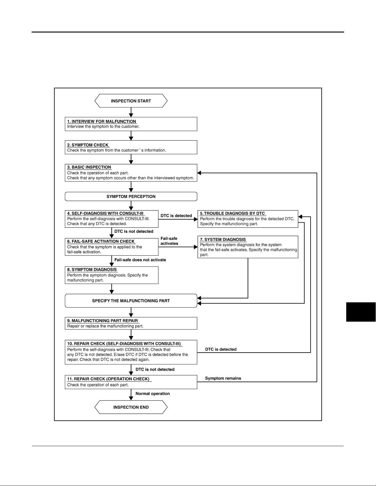
OVERALL SEQUENCE
A
B
C
D
E
F
G
H
JPLIA0313GB
I
J
K
EXL
M
N
O
P
DETAILED FLOW
1.INTERVIEW FOR MALFUNCTION
Interview the symptom to the customer.
EXL-7
Page 8

DIAGNOSIS AND REPAIR WORKFLOW
Revision: 2007 November 2008 EX35
< BASIC INSPECTION >
>> GO TO 2.
[XENON TYPE]
2.SYMPTOM CHECK
Check the symptom from the customer's information.
>> GO TO 3.
3.BASIC INSPECTION
Check the operation of each part. Check that any symptom occurs other than the interviewed symptom.
>> GO TO 4.
4.SELF-DIAGNOSIS WITH CONSULT-III
Perform the self-diagnosis with CONSULT-III. Check that any DTC is detected.
Is any DTC detected?
YES >> GO TO 5.
NO >> GO TO 6.
5.TROUBLE DIAGNOSIS BY DTC
Perform the trouble diagnosis for the detected DTC. Specify the malfunctioning part.
>> GO TO 9.
6.FAI L - SAFE ACTIVATION CHECK
Check that the symptom is applied to the fail-safe activation.
Does the fail-safe activate?
YES >> GO TO 7.
NO >> GO TO 8.
7.SYSTEM DIAGNOSIS
Perform the system diagnosis for the system that the fail-safe activates. Specify the malfunctioning part.
>> GO TO 9.
8.SYMPTOM DIAGNOSIS
Perform the symptom diagnosis. Specify the malfunctioning part.
>> GO TO 9.
9.MALFUNCTION PART REPAIR
Repair or replace the malfunctioning part.
>> GO TO 10.
10.REPAIR CHECK (SELF-DIAGNOSIS WITH CONSULT-III)
Perform the self-diagnosis with CONSULT-III. Check that any DTC is not detected. Erase DTC if DTC is
detected before the repair. Check that DTC is not detected again.
Is any DTC detected?
YES >> GO TO 5.
NO >> GO TO 11.
11.REPAIR CHECK (OPERATION CHECK)
Check the operation of each part.
Does it operate normally?
YES >> INSPECTION END
NO >> GO TO 3.
EXL-8
Page 9

< BASIC INSPECTION >
Revision: 2007 November 2008 EX35
INSPECTION AND ADJUSTMENT
[XENON TYPE]
INSPECTION AND ADJUSTMENT
ADDITIONAL SERVICE WHEN REPLACING CONTROL UNIT (AFS CONTROL UNIT)
ADDITIONAL SERVICE WHEN REPLACING CONTROL UNIT (AFS CONTROL UNIT) : Description
Perform “LEVELIZER ADJUSTMENT” with CONSULT-III when replacing the AFS control unit.
INFOID:0000000003135252
ADDITIONAL SERVICE WHEN REPLACING CONTROL UNIT (AFS CONTROL UNIT) : Special Repair Requirement
INFOID:0000000003135253
1.LEVELIZER ADJUSTMENT
Perform “LEVELIZER ADJUSTMENT”.
>> Refer to EXL-9, "LEVELIZER ADJUSTMENT : Special Repair Requirement"
ADDITIONAL SERVICE WHEN REPLACING CONTROL UNIT (HEIGHT SENSOR)
ADDITIONAL SERVICE WHEN REPLACING CONTROL UNIT (HEIGHT SENSOR) : Description
Perform “LEVELIZER ADJUSTMENT” with CONSULT-III when replacing the height sensor.
.
INFOID:0000000003596961
A
B
C
D
E
F
G
H
ADDITIONAL SERVICE WHEN REPLACING CONTROL UNIT (HEIGHT SENSOR) : Special Repair Requirement
INFOID:0000000003596962
1.LEVELIZER ADJUSTMENT
Perform “LEVELIZER ADJUSTMENT”.
>> Refer to EXL-9, "LEVELIZER ADJUSTMENT : Special Repair Requirement"
.
LEVELIZER ADJUSTMENT
LEVELIZER ADJUSTMENT : Description INFOID:0000000003135254
Perform “LEVELIZER ADJUSTMENT” when installing, removing, and replacing the height sensor and the suspension components.
LEVELIZER ADJUSTMENT : Special Repair Requirement INFOID:0000000003135255
1.CHECK VEHICLE CONDITION
1. Park the vehicle in the straight-forward position.
2. Unload the vehicle (no passenger aboard).
>> GO TO 2.
2.LEVELIZER ADJUSTMENT
CONSULT-III WORK SUPPORT
1. Select "LEVELIZER ADJUSTMENT" of ADAPTIVE LIGHT work support item.
2. Select "START".
3. When "ADJUSTMENT IS COMPLETED", select "END".
CAUTION:
If "CAN NOT BE TESTED" is indicated, AFS control unit detects that the height sensor signal
changes. The levelizer adjustment is cancelled. In this case, turn the ignition switch OFF to prevent the vehicle from the height change. Perform the levelizer adjustment again.
I
J
K
EXL
M
N
O
P
EXL-9
Page 10

INSPECTION AND ADJUSTMENT
Revision: 2007 November 2008 EX35
< BASIC INSPECTION >
Is the levelizer adjustment completed?
YES >> GO TO 3.
NO >> Perform the levelizer adjustment again.
3.SELF-DIAGNOSIS RESULT CHECK
Perform self-diagnosis with CONSULT-III. Check that any DTC is not detected.
Is any DTC detected?
YES >> GO TO 2.
NO >> Levelizer adjustment completed
[XENON TYPE]
EXL-10
Page 11
< FUNCTION DIAGNOSIS >
Revision: 2007 November 2008 EX35
HEADLAMP SYSTEM
[XENON TYPE]
FUNCTION DIAGNOSIS
HEADLAMP SYSTEM
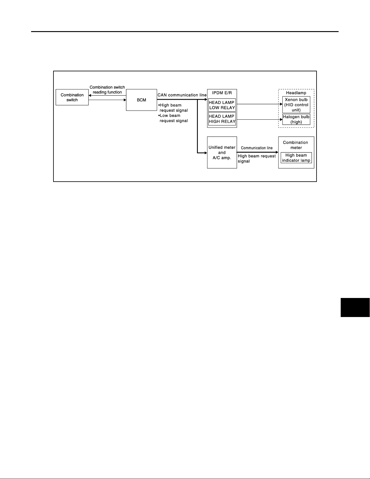
System Diagram INFOID:0000000003534165
JPLIA0910GB
System Description INFOID:0000000003534166
OUTLINE
Headlamp is controlled by combination switch reading function and headlamp control function of BCM, and
relay control function of IPDM E/R.
HEADLAMP (LO) OPERATION
• BCM detects the combination switch condition with the combination switch reading function.
• BCM transmits the low beam request signal to IPDM E/R with CAN communication according to the headlamp (LO) ON condition.
A
B
C
D
E
F
G
H
I
J
Headlamp (LO) ON condition
- Lighting switch 2ND
• IPDM E/R turns the integrated headlamp low relay ON, and turns the headlamp ON according to the low
beam request signal.
HEADLAMP (HI) OPERATION
• BCM transmits the high beam request signal to IPDM E/R and the combination meter (through the unified
meter and A/C amp.) with CAN communication according to the headlamp (HI) ON condition.
Headlamp (HI) ON condition
- Lighting switch HI with the lighting switch 2ND
- Lighting switch PASS
• Combination meter turns the high beam indicator lamp ON according to the high beam request signal.
• IPDM E/R turns the integrated headlamp high relay ON, and turns the headlamp ON according to the high
beam request signal.
K
EXL
M
N
O
P
EXL-11
Page 12
< FUNCTION DIAGNOSIS >
Revision: 2007 November 2008 EX35
HEADLAMP SYSTEM
[XENON TYPE]
Component Parts Location
INFOID:0000000003534167
JPLIA0942ZZ
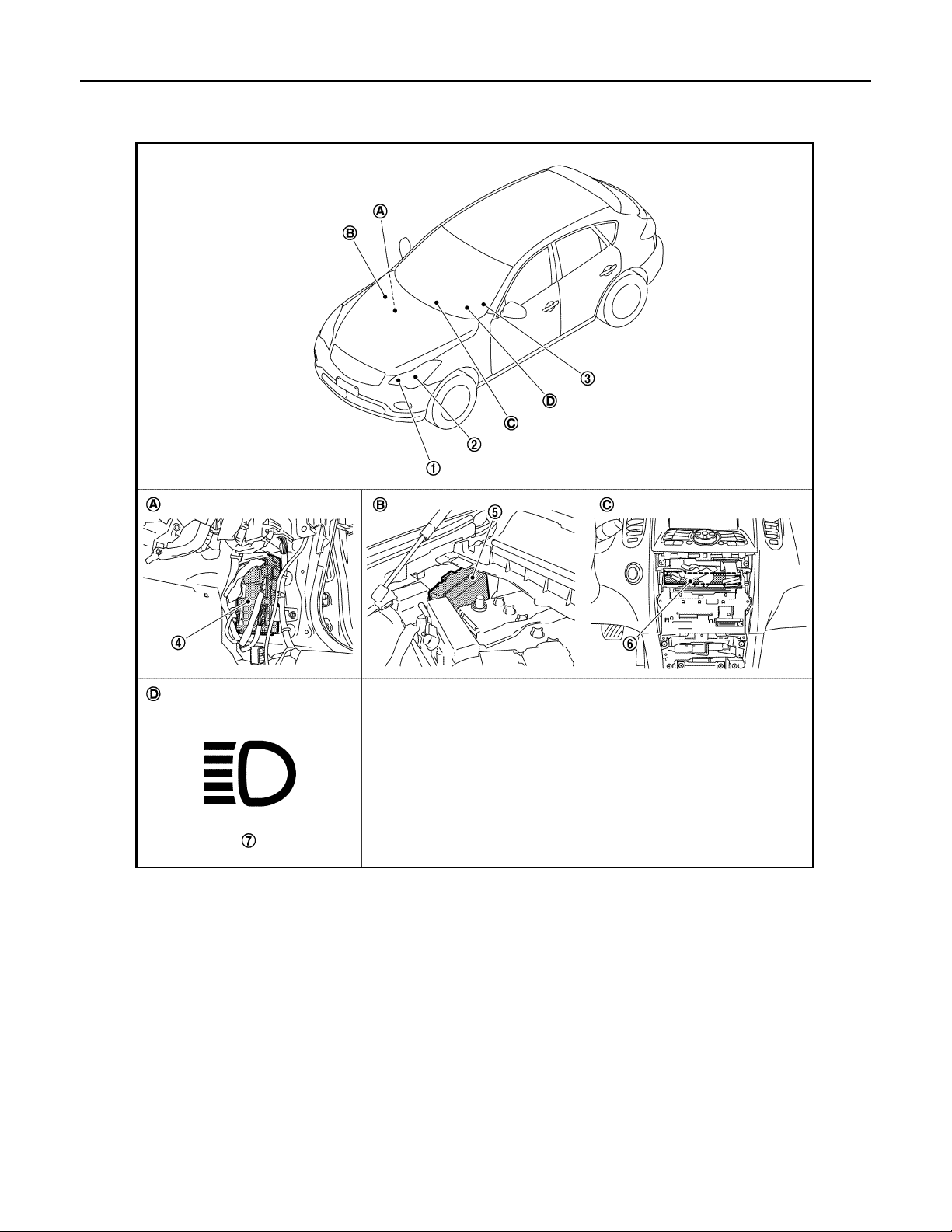
1. Headlamp (HI) 2. Headlamp (LO) 3. Combination switch
4. BCM 5. IPDM E/R 6. Unified meter and A/C amp.
7. High beam indicator lamp
A. Dash side lower (Passenger side) B. Engine room dash panel (RH) C. Behind the cluster lid C
D. On the combination meter
EXL-12
Page 13
HEADLAMP SYSTEM
Revision: 2007 November 2008 EX35
< FUNCTION DIAGNOSIS >
[XENON TYPE]
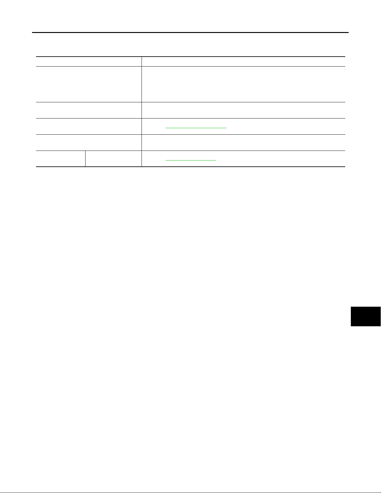
Component Description INFOID:0000000003534168
Part Description
• Detects each switch condition by the combination switch reading function.
• Judges that the headlamp is turne d ON ac co rdin g to the vehicle condition.
BCM
IPDM E/R
Combination switch
(Lighting & turn signal switch)
Combination meter
(High beam indicator lamp)
Front combination
lamp assembly
• HID control unit
• Xenon bulb
- Requests the headlamp relay (HI/LO) ON to IPDM E/R (with CAN communication).
- Requests the high beam indicator lamp ON to the combination meter [with CAN
communication (through unified meter and A/C amp.)].
Controls the integrated relay, and supplies voltage to the load according to the request
from BCM (with CAN communication).
Refer to BCS-8, "System Diagram"
Turns the high beam indicator lamp ON according to the request from BCM [with CAN
communication (through unified meter and A/C amp.)].
Refer to EXL-71, "Description"
.
.
A
B
C
D
E
F
G
H
I
J
K
EXL
M
N
O
EXL-13
P
Page 14
AUTO LIGHT SYSTEM
Revision: 2007 November 2008 EX35
< FUNCTION DIAGNOSIS >
[XENON TYPE]
AUTO LIGHT SYSTEM
System Diagram INFOID:0000000003135260
JPLIA0005GB
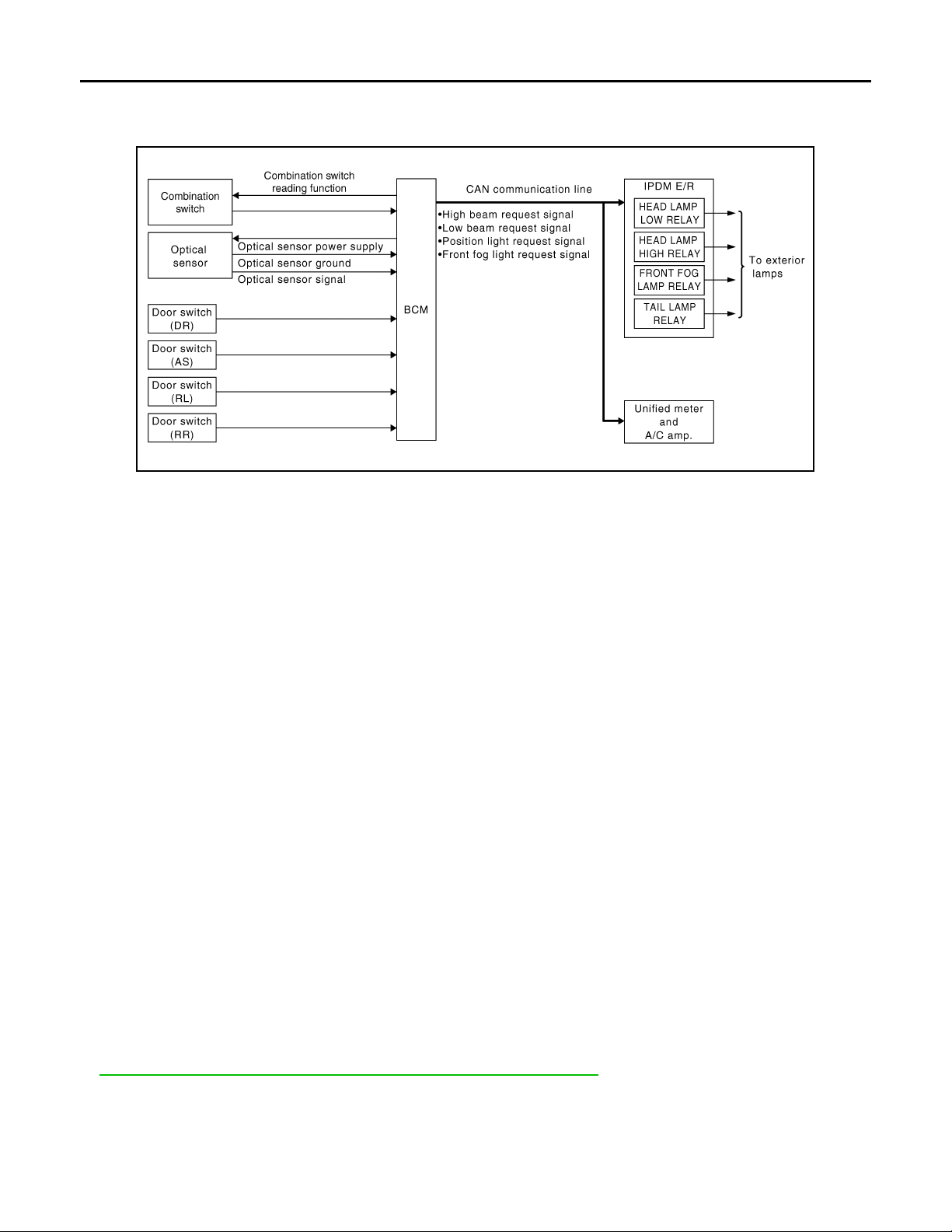
System Description INFOID:0000000003135261
OUTLINE
• Auto light system is controlled by each function of BCM and IPDM E/R.
Control by BCM
- Combination switch reading function
- Headlamp control function
- Auto light function
- Delay timer function
Control by IPDM E/R
- Relay control function
• Auto light system has the auto light function and the delay timer function.
- Auto light function turns the exterior lamps* and each illumination ON/OFF automatically according to the
outside brightness.
- When auto light system turns the exterior lamps ON with the ignition switch OFF, delay timer function turns
the exterior lamps OFF depending on the vehicle condition with the auto light function after a certain period
of time.
*: Headlamp (LO/HI), parking lamp, tail lamp, and front fog lamp (Headlamp HI and front fog lamp depend on
the combination switch condition.)
AUTO LIGHT FUNCTION
• BCM detects the combination switch condition with the combination switch reading function.
• BCM supplies voltage to optical sensor when the ignition switch is turned ON or ACC.
• Optical sensor converts outside brightness (lux) to voltage and transmits the optical sensor signal to BCM.
• BCM judges outside brightness from the optical sensor signal and judges ON/OFF condition of the exterior
lamp and each illumination according to the outside brightness.
• BCM transmits each request signal to IPDM E/R with CAN communication according to ON/OFF condition
by the auto light function.
NOTE:
ON/OFF timing differs based on the sensitivity from the setting. The setting can be set by CONSULT -III. Refer
to EXL-33, "HEADLAMP : CONSULT-III Function (BCM - HEAD LAMP)"
.
DELAY TIMER FUNCTION
BCM turns the exterior lamp OFF depending on the vehicle condition with the auto light function when the ignition switch is turned OFF.
• Turns the exterior lamp OFF 5 minutes after detecting that any door opens (Door switch ON).
• Turns the exterior lamp OFF a certain period of time* after closing all doors (Door switch ON→OFF).
EXL-14
Page 15
AUTO LIGHT SYSTEM
Revision: 2007 November 2008 EX35
< FUNCTION DIAGNOSIS >
• Turns the exterior lamp OFF with the ignition switch ACC or the light switch OFF.
*: The preset time is 45 seconds. The timer operating time can be set by CONSULT-III. Refer to EXL-33,
"HEADLAMP : CONSULT-III Function (BCM - HEAD LAMP)".
NOTE:
When any position other than the light switch AUTO is set, the auto light system function switches to the exterior lamp battery saver function.
[XENON TYPE]
Component Parts Location INFOID:0000000003135262
A
B
C
D
E
F
G
JPLIA0943ZZ
H
I
J
K
EXL
M
N
O
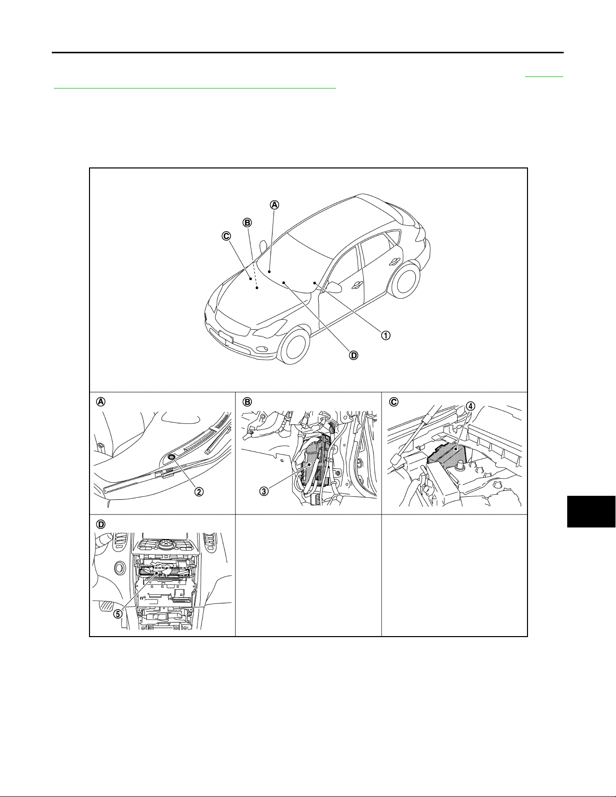
1. Combination switch 2. Optical sensor 3. BCM
4. IPDM E/R 5. Unified meter and A/C amp.
A. Instrument upper panel (RH) B. Dash side lower (Passenger side) C. Engine room dash panel (RH)
D. Behind the cluster lid C
EXL-15
P
Page 16
< FUNCTION DIAGNOSIS >
Revision: 2007 November 2008 EX35
AUTO LIGHT SYSTEM
[XENON TYPE]
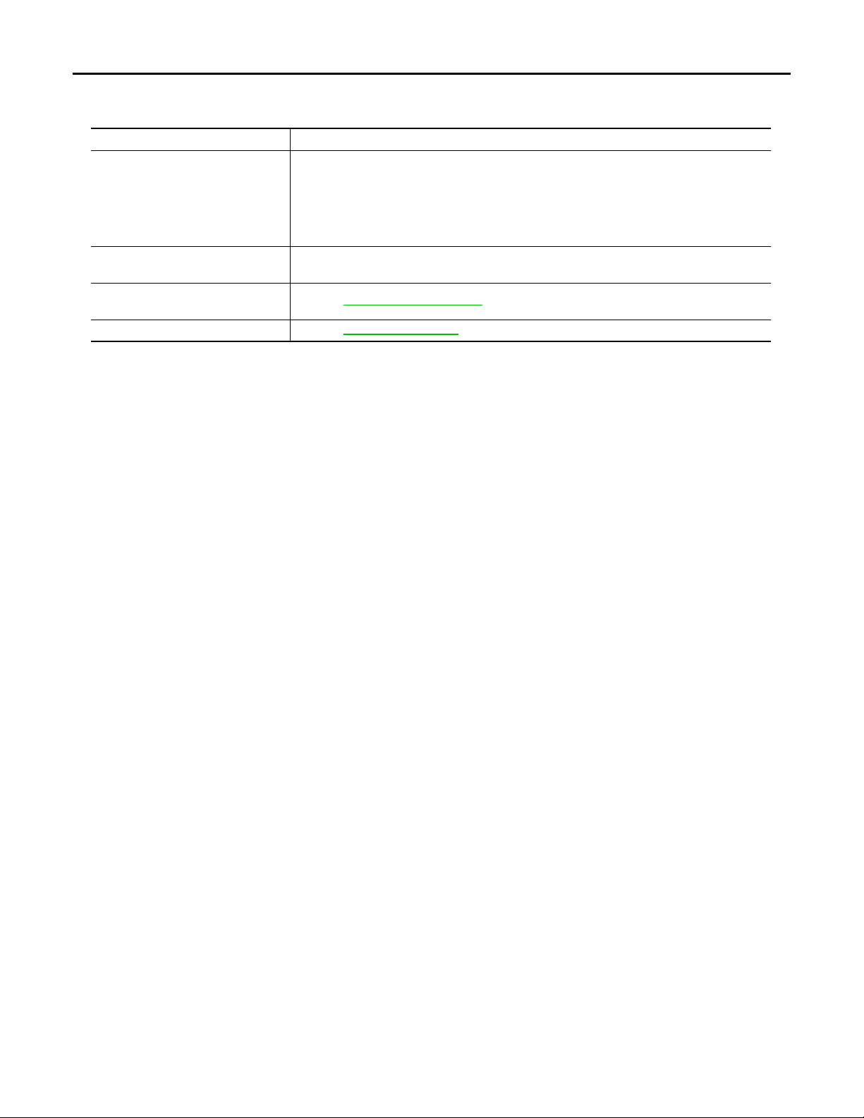
Component Description
Part Description
• Judges each switch condition by the combination switch reading function.
• Judges the outside brightness from the optical sensor signal.
BCM
IPDM E/R
Combination switch
(Lighting & turn signal switch)
Optical sensor Refer to EXL-81, "Description"
• Judges the OFF timing according to the vehicle condition.
• Judges the ON/OFF status of the exterior lamp and each illumination according to the
outside brightness an d the vehicle condition.
Requests ON/OFF of each relay to IPDM E/R (with CAN communication).
Controls the integrated relay, and supplies voltage to the load according to the request
from BCM (with CAN communication).
Refer to BCS-8, "System Diagram"
INFOID:0000000003135263
.
.
EXL-16
Page 17
< FUNCTION DIAGNOSIS >
Revision: 2007 November 2008 EX35
DAYTIME RUNNING LIGHT SYSTEM
[XENON TYPE]
DAYTIME RUNNING LIGHT SYSTEM
System Diagram INFOID:0000000003135264
JPLIA0006GB
System Description INFOID:0000000003135265
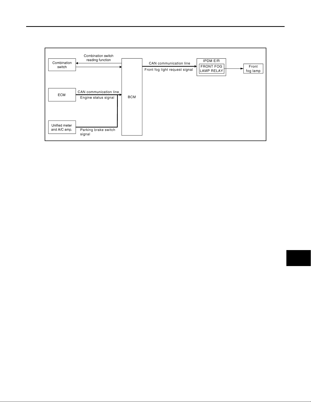
OUTLINE
• Turns the front fog lamp ON as the daytime running light.
• Daytime running light is controlled by daytime running light control function and combination switch reading
function of BCM, and relay control function of IPDM E/R.
A
B
C
D
E
F
G
H
DAYTIME RUNNING LIGHT OPERATION
• BCM detects the combination switch condition by the combination switch reading function.
• BCM detects the vehicle condition depending on the following signals.
- Engine condition signal (received from ECM with CAN communication)
- Parking brake switch signal (received from unified meter and A/C amp. with CAN communication)
• BCM transmits the front fog light request signal to IPDM E/R with CAN communication according to the daytime running light ON condition.
Daytime running light ON condition
- While the engine running with the parking brake released
Daytime running light OFF condition
- Engine stopped
- Headlamp ON (Passing included)
• IPDM E/R turns the integrated front fog lamp relay ON and turns the front fog lamp ON according to the front
fog light request signal.
I
J
K
EXL
M
N
O
P
EXL-17
Page 18
< FUNCTION DIAGNOSIS >
Revision: 2007 November 2008 EX35
DAYTIME RUNNING LIGHT SYSTEM
[XENON TYPE]
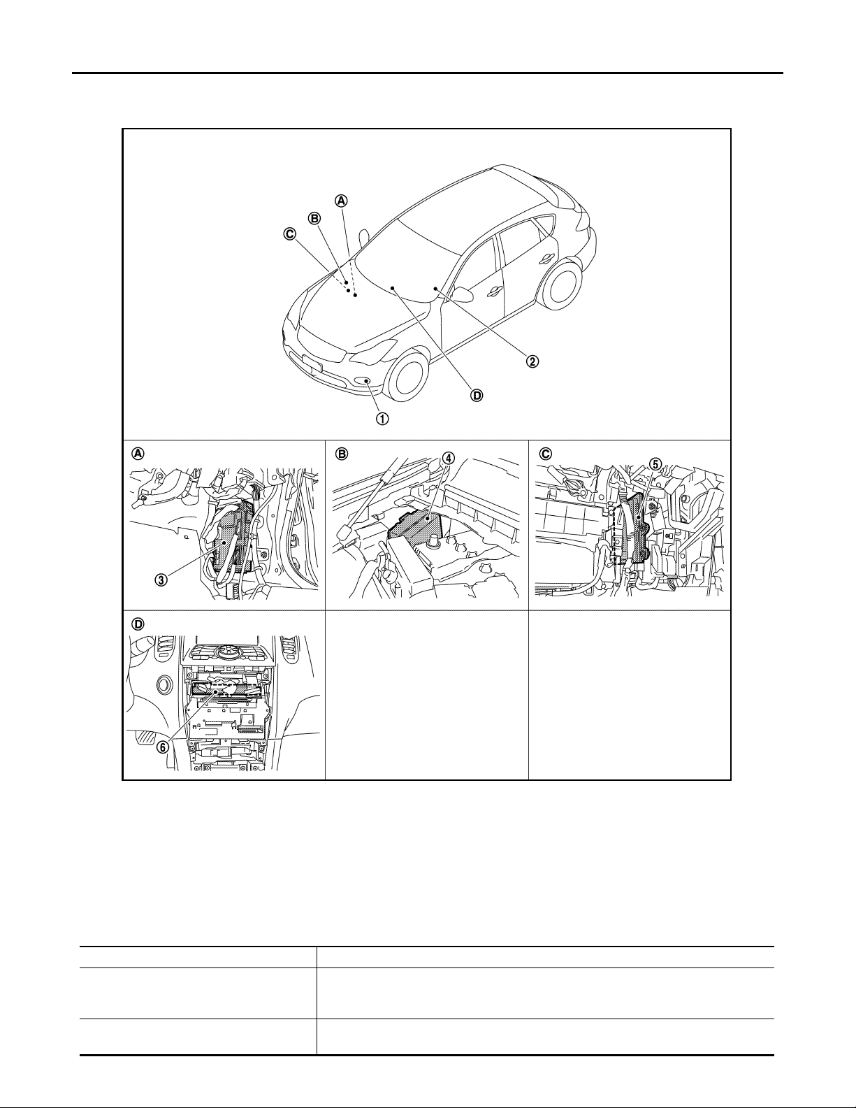
Component Parts Location
INFOID:0000000003135266
JPLIA0944ZZ
1. Daytime running light
(Front fog lamp)
4. IPDM E/R 5. ECM 6. Unified meter and A/C amp.
A. Dash side lower (Passenger side) B. Engine room dash panel (RH) C. Behind the glove box
D. Behind the cluster lid C
2. Combination switch 3. BCM
Component Description INFOID:0000000003135267
Part Description
• Judges each switch condition with the combination switch reading function.
BCM
IPDM E/R
• Judges the headlamp ON/OFF status according to the vehicle condition. Requests
the front fog lamp relay ON to IPDM E/R (with CAN communication).
Controls the integrated relay an d supplies vol tage to the load accord ing to the re quest
from BCM (with CAN communication).
EXL-18
Page 19
< FUNCTION DIAGNOSIS >
Revision: 2007 November 2008 EX35
DAYTIME RUNNING LIGHT SYSTEM
[XENON TYPE]
Part Description
Combination switch
(Lighting & turn signal switch)
ECM Transmits the engine condition signal to BCM with CAN communication.
Unified meter and A/C amp. Transmits the parking brake switch signal to BCM with CAN communication.
Refer to BCS-8, "System Diagram"
.
A
B
C
D
E
F
G
H
I
J
K
EXL
M
N
O
P
EXL-19
Page 20
ACTIVE ADAPTIVE FRONT-LIGHTING SYSTEM
Revision: 2007 November 2008 EX35
< FUNCTION DIAGNOSIS >
[XENON TYPE]
ACTIVE ADAPTIVE FRONT-LIGHTING SYSTEM
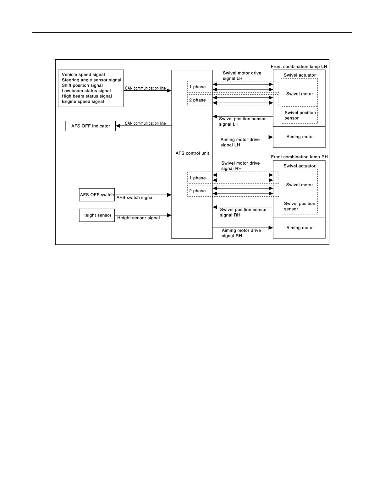
System Diagram INFOID:0000000003135268
JPLIA0912GB
System Description INFOID:0000000003135269
OUTLINE
• AFS (ACTIVE ADAPTIVE FRONT-LIGHTING SYSTEM) is controlled by AFS control unit.
• AFS has AFS control (swivel control) and the headlamp auto aiming control.
- AFS control swivels the headlamp to the steering direction.
- Headlamp auto aiming control moves the headlamp light axis up/down according to the vehicle height.
AFS (ADAPTIVE FRONT-LIGHTING SYSTEM)
AFS Control Description
• AFS control controls the headlamp (right) only when the steering wheel is turned rightward, and the headlamp (left) only when the steering wheel is turned leftward.
• AFS control unit detects the vehicle condition necessary for AFS control with the following signals.
- AFS switch signal
- Steering angle sensor signal (received from steering angle sensor with CAN communication)
- Engine speed signal (received from ECM with CAN communication)
- Shift position signal (received from TCM with CAN communication)
- Low beam status and high beam status (received from IPDM E/R with CAN communication)
- Vehicle speed signal (received from unified meter and A/C amp. with CAN communication)
• When the operation conditions are satisfied, AFS control unit controls the swivel angle depending on the
steering angle and the vehicle speed.
AFS operation condition
- Swivel actuator initialization completed
- AFS OFF switch OFF
- Headlamp ON
- While the engine running
- Selector lever position other than "P" or "R"
- V ehi cle speed approximately 25 km/h (15.5 MPH) or more (lef t swivel only; Right swivel activates regardless
of the vehicle speed.)
EXL-20
Page 21

ACTIVE ADAPTIVE FRONT-LIGHTING SYSTEM
Revision: 2007 November 2008 EX35
< FUNCTION DIAGNOSIS >
Swivel Actuator Initialization
• AFS control unit performs the swivel actuator initialization when detecting that the engine starts.
- Swivels the headlamp to the vehicle-center side until it hits the stopper.
- Returns the swivel angle from the stopper. Completes the initialization with regarding the returned position
as the swivel angle 0° (straight-forward position).
Swivel Operation
• AFS control unit transmits the drive signal to the swivel actuator when activation conditions are satisfied.
And swivels the headlamp.
- The swivel starts after steering approximately 20° or more from straight-forward position.
NOTE:
The steering angle differs between right turn and left turn.
- The swivel angle becomes the maximum angle toward the driving direction if the steering angle is approximately 90° or more depending on the vehicle speed. The swivel angle is maintained by shutting off the drive
signal.
- The swivel starts, and returns to the swivel angle 0° (straight-forward position) when the steering is returned
to the straight-forward position.
• AFS control unit returns the swivel angle to the straight-forward position, and stops the swivel regardless of
the steering angle if the operation condition is not satisfied while the swivel angle is 0°.
AFS OFF Indicator Lamp
• AFS control unit transmits AFS OFF indicator lamp signal to the combination meter (through the unified
meter and A/C amp.) with CAN communication.
• Combination meter turns AFS OFF indicator lamp ON/OFF/blinking according to AFS OFF indicator lamp
signal.
- AFS OFF indicator lamp is turned ON for 1 second for the AFS OFF indicator lamp bulb check when the ignition switch is turned ON. AFS OFF indicator lamp is turned OFF within 1 second when the engine starts.
- AFS OFF indicator lamp is turned OFF when AFS OFF switch is turned ON.
- AFS OFF indicator lamp blinks (1 second each) if AFS control unit detects a specific DTC.
NOTE:
Combination meter blinks AFS OFF indicator lamp (approximately 1 second each) if AFS OFF indicator
lamp signal is not received from AFS control unit.
[XENON TYPE]
A
B
C
D
E
F
G
H
I
HEADLAMP AUTO AIMING
Headlamp Auto Aiming Control Description
• Headlamp auto aiming control controls the headlamp light axis height appropriately according to the vehicle
height.
• AFS control unit detects the vehicle condition necessary for headlamp auto aiming control with the following
signals.
- Height sensor signal
- Engine speed signal (received from ECM with CAN communication)
- Low beam status signal and high beam status signal (received from IPDM E/R with CAN communication)
- Vehicle speed signal (received from unified meter and A/C amp. with CAN communication)
• When the operation conditions are satisfied, AFS control unit transmits the aiming motor drive signal for
adjusting the headlamp axis height.
Headlamp auto aiming operation condition
- Headlamp ON
- While the engine running
- Vehicle speed (Control mode is switched according to the driving condition.)
Headlamp Auto Aiming Operation
• AFS control unit calculates the vehicle pitch angle from the height sensor signal. AFS control unit judges the
angle for adjusting the axis gap from the preset position.
CAUTION:
Adjusted axis position may differ from the preset position although the headlamp auto aiming activates properly if the suspension is replaced or worn.
• AFS control unit controls the headlamp axis by changing the aiming motor drive signal output according to
the vehicle-rearward height when detecting the following vehicle condition. Output is maintained if other condition than following is detected.
- Engine starts.
- Headlamp is turned ON.
J
K
EXL
M
N
O
P
EXL-21
Page 22
ACTIVE ADAPTIVE FRONT-LIGHTING SYSTEM
Revision: 2007 November 2008 EX35
< FUNCTION DIAGNOSIS >
- Vehicle posture becomes stable after changing the vehicle posture change is detected with the headlamp
ON and the vehicle stopped.
- Vehicle speed is maintained with the headlamp ON and the vehicle driven.
[XENON TYPE]
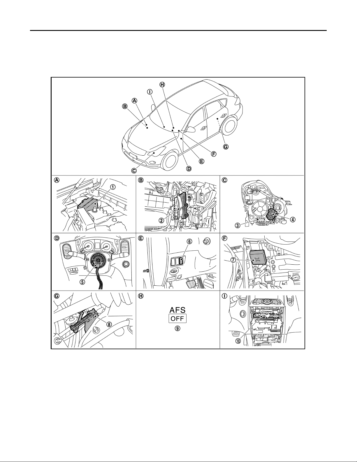
Component Parts Location INFOID:0000000003135270
JPLIA0996ZZ
1. IPDM E/R 2. ECM 3. Swivel actuator
4. Aiming motor 5. Steering angle sensor 6. AFS OFF switch
7. AFS control unit 8. Height sensor 9. AFS OFF indicator lamp
10. Uni fie d me ter an d A/C amp.
A. Engine room dash panel (RH) B. Behind the glove box C. Front combination lamp (back)
D. Steering column cover (inside) E. Instrument driver lower panel F. Behind the instrument driver lower
panel
G. Rear suspension member (LH) H. On the combination meter I. Behind the cluster lid C
Component Description INFOID:0000000003135271
EXL-22
Page 23
ACTIVE ADAPTIVE FRONT-LIGHTING SYSTEM
Revision: 2007 November 2008 EX35
< FUNCTION DIAGNOSIS >
[XENON TYPE]
Part Description
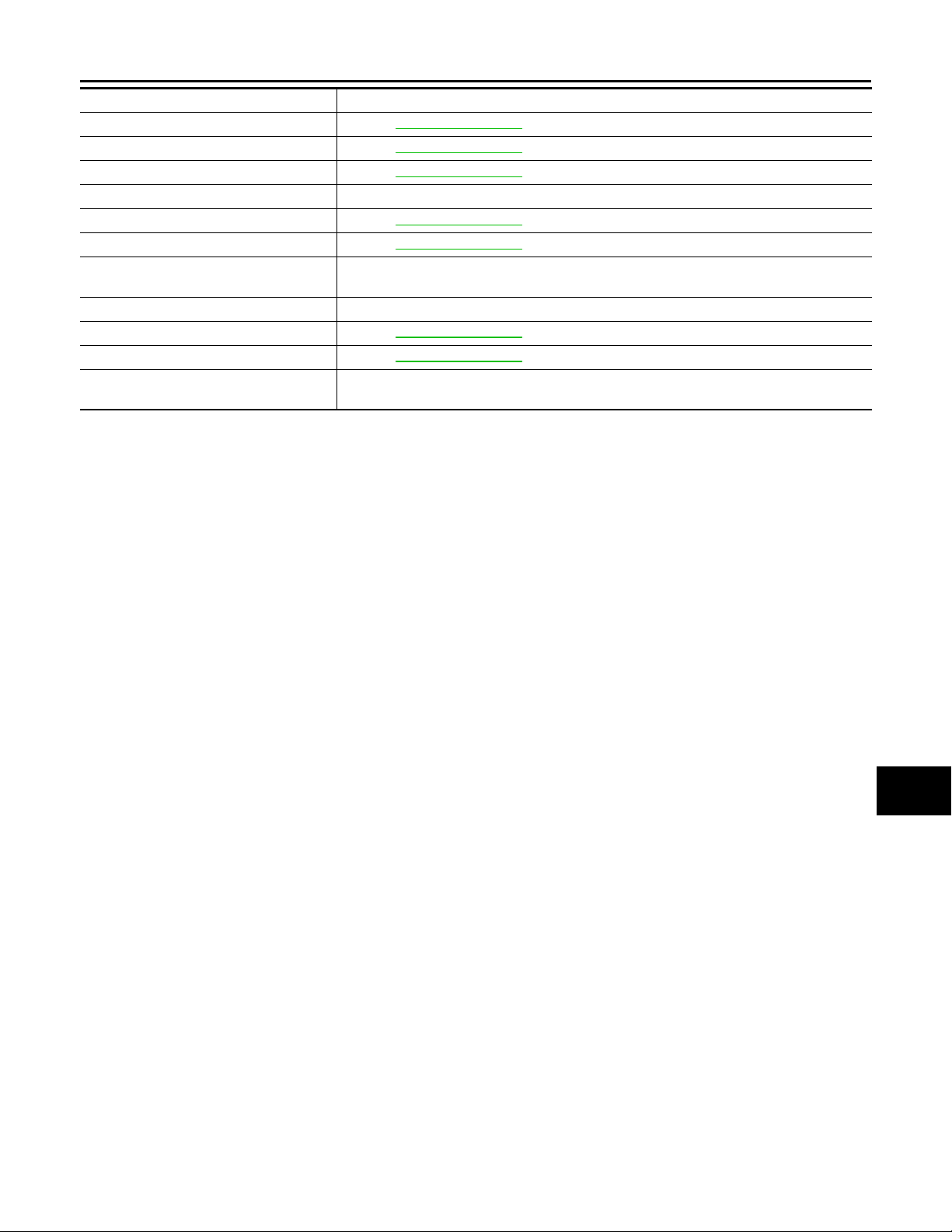
AFS control unit Refer to EXL-56, "Description"
Swivel actuator Refer to EXL-44, "Description"
Aiming motor Refer to EXL-73, "Description"
AFS OFF switch Inputs AFS OFF switch ON/OFF signal to AFS control unit.
Height sensor Refer to EXL-50, "Description"
Steering angle sensor Refer to EXL-59, "Description"
IPDM E/R
ECM Transmits the engine speed signal to AFS control unit with CAN communication.
TCM Refer to EXL-53, "Description"
Unified meter and A/C amp. Refer to EXL-54, "Description"
Combination meter
Transmits the headlamp (LO) ON signal and the headlamp (HI) ON signal to AFS control
unit with CAN communication.
Turns AFS OFF indicator lamp ON/OFF/blinking according to AFS control unit request [with
CAN communication (through unified me ter and A/C amp.)].
.
.
.
.
.
.
.
A
B
C
D
E
F
G
H
I
J
K
EXL
M
N
O
P
EXL-23
Page 24
FRONT FOG LAMP SYSTEM
Revision: 2007 November 2008 EX35
< FUNCTION DIAGNOSIS >
[XENON TYPE]
FRONT FOG LAMP SYSTEM
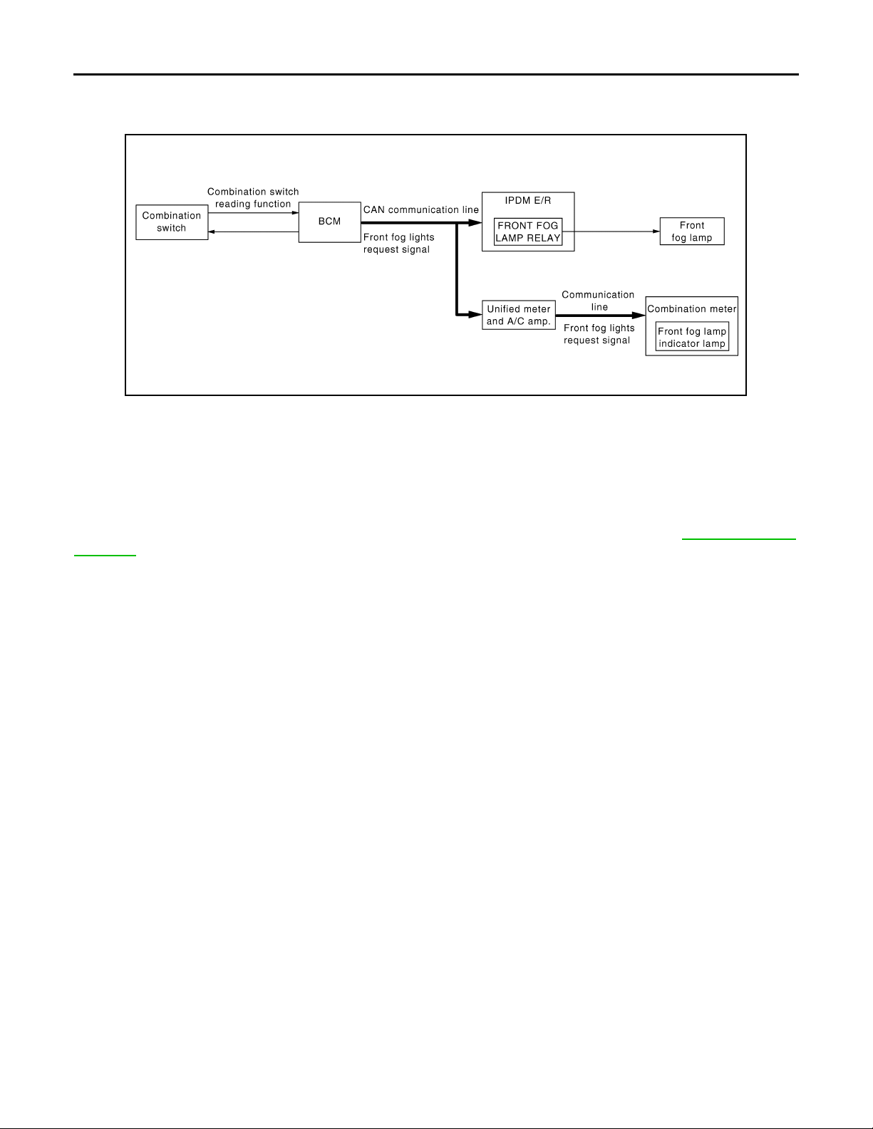
System Diagram INFOID:0000000003135272
JPLIA0158GB
System Description INFOID:0000000003135273
OUTLINE
Front fog lamp is controlled by combination switch reading function and front fog lamp control function of BCM,
and relay control function of IPDM E/R.
NOTE:
For Canada models, the front fog lamp is turned ON as the daytime running light. Refer to EXL-30, "System
Diagram" for the detail.
FRONT FOG LAMP OPERATION
• BCM detects the combination switch condition by the combination switch reading function.
• BCM transmits the front fog light request signal to IPDM E/R and the combination meter (through the unified
meter and A/C amp.) with CAN communication according to the front fog lamp ON condition.
Front fog lamp ON condition
- Front fog lamp switch ON with the headlamp ON (except for the high beam ON)
• IPDM E/R turns the integrated front fog lamp relay ON, and turns the front fog lamp ON according to the
front fog light request signal.
• Combination meter turns the front fog lamp indicator lamp ON according to the front fog light request signal.
EXL-24
Page 25
FRONT FOG LAMP SYSTEM
Revision: 2007 November 2008 EX35
< FUNCTION DIAGNOSIS >
[XENON TYPE]
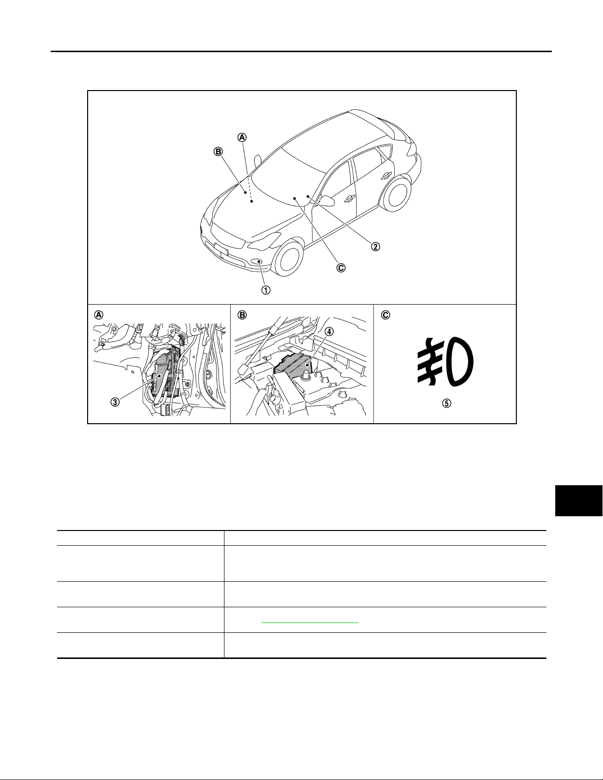
Component Parts Location INFOID:0000000003135274
A
B
C
D
E
F
G
JPLIA0945ZZ
1. Front fog lamp 2. Combination switch 3. BCM
4. IPDM E/R 5. Front fog lamp indicator lamp
A. Dash side lower (Passenger side) B. Engine room dash panel (RH) C. On the combination meter
Component Description INFOID:0000000003135275
Part Description
• Judges each switch condition by the combination switch reading function.
BCM
IPDM E/R
Combination switch
(Lighting & turn signal switch)
Combination meter
(Front fog lamp indicator lamp)
• Judges the front fog lamp ON/OFF status according to the vehicle condition. Requests the front fog lamp relay ON to IPDM E/R (with CAN communication).
Controls the integrated relay and supplies voltage to the load according to the request
from BCM (with CAN communication).
Refer to BCS-8, "System Diagram"
Turns the front fog lamp indicator lamp ON according to the request from BCM [with
CAN communication (through the uni fied meter and A/C amp.)].
.
H
I
J
K
EXL
M
N
O
P
EXL-25
Page 26
TURN SIGNAL AND HAZARD WARNING LAMP SYSTEM
Revision: 2007 November 2008 EX35
< FUNCTION DIAGNOSIS >
[XENON TYPE]
TURN SIGNAL AND HAZARD WARNING LAMP SYSTEM
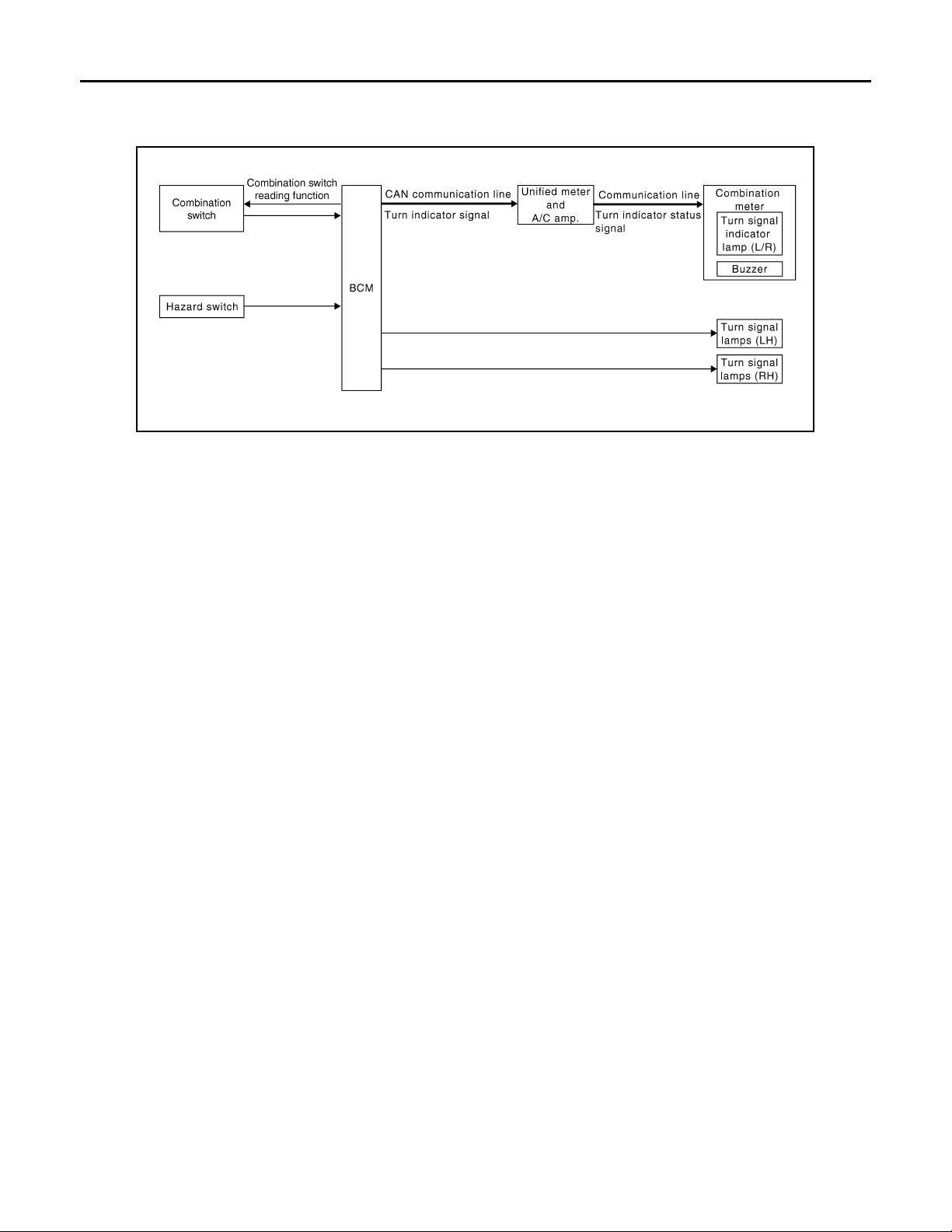
System Diagram INFOID:0000000003135276
JPLIA0003GB
System Description INFOID:0000000003135277
OUTLINE
Turn signal and the hazard warning lamp is controlled by combination switch reading function and the flasher
control function of BCM.
TURN SIGNAL LAMP OPERATION
• BCM detects the combination switch condition by the combination switch reading function.
• BCM supplies voltage to the right (left) turn signal lamp circuit when the ignition switch is turned ON and the
turn signal switch is in the right (left) position. BCM blinks the turn signal lamp.
HAZARD WARNING LAMP OPERATION
BCM supplies voltage to both turn signal lamp circuit when the hazard switch is turned ON. BCM blinks the
hazard warning lamp.
TURN SIGNAL INDICATOR LAMP AND TURN SIGNAL SOUND OPERATION
• BCM transmits the turn signal indicator lamp signal to the combination meter (through the unified meter and
A/C amp.) with CAN communication while the turn signal lamp and the hazard warning lamp operating.
• Combination meter outputs the turn signal sound with the integrated buzzer while blinking the turn signal
indicator lamp according to the turn signal indicator lamp signal.
HIGH FLASHER OPERATION (FAIL-SAFE)
• BCM detects the turn signal lamp circuit status from the current value.
• BCM increases the turn signal lamp blinking speed if the bulb or harness open is detected with the turn signal lamp operating.
NOTE:
The blinking speed is normal while operating the hazard warning lamp.
EXL-26
Page 27
TURN SIGNAL AND HAZARD WARNING LAMP SYSTEM
Revision: 2007 November 2008 EX35
< FUNCTION DIAGNOSIS >
[XENON TYPE]
Component Parts Location INFOID:0000000003135278
A
B
C
D
E
F
G
JPLIA0946ZZ
1. Hazard warning switch 2. Front turn signal lamp 3. Combination switch
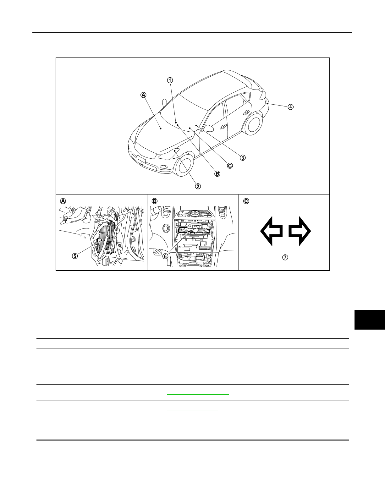
4. Rear turn signal lamp 5. BCM 6. Unified meter and A/C amp.
7. Turn signal indicator lamp
A. Dash side lower (Passenger side) B. Behind the cluster lid C C. On the com bination meter
Component Description INFOID:0000000003135279
Part Description
• Judges each switch condition by the combination switch reading function.
• Judges the blinks of the turn signal lamp and the hazard warning lamp from each
BCM
Combination switch
(Lighting & turn signal switch)
Hazard switch
(Multifunction switch)
Combination meter
(Turn signal indicator lamp & buzzer)
switch status. The applicable turn signal lamp blinks.
Requests the turn signal indicator lamp blink to the combination meter (with CAN
communication).
Refer to BCS-8, "System Diagram"
Refer to EXL-84, "Description"
Blinks the turn signal indicator lamp and outputs the turn signal operating sound with
integrated buzzer according to the request from BCM [with CAN communication
(through unified meter and A/C amp.)].
.
.
H
I
J
K
EXL
M
N
O
P
EXL-27
Page 28
PARKING, LICENSE PLATE AND TAIL LAMPS SYSTEM
Revision: 2007 November 2008 EX35
< FUNCTION DIAGNOSIS >
[XENON TYPE]
PARKING, LICENSE PLATE AND TAIL LAMPS SYSTEM
System Diagram INFOID:0000000003135280
JPLIA1027GB
System Description INFOID:0000000003135281
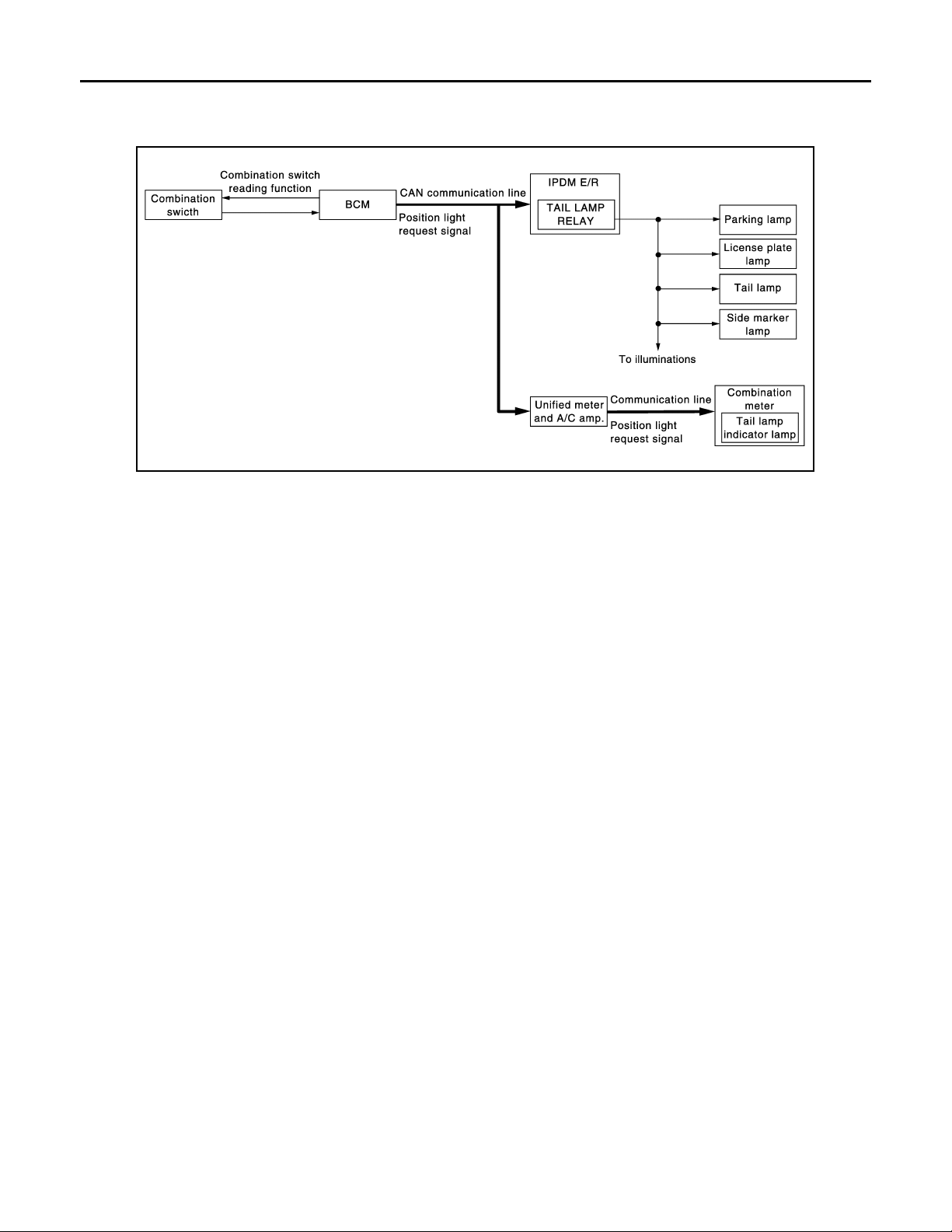
OUTLINE
Parking, license plate, side marker and tail lamps are controlled by combination switch reading function and
headlamp control function of BCM, and relay control function of IPDM E/R.
PARKING, LICENSE PLATE, SIDE MARKER AND TAIL LAMPS OPERATION
• BCM detects the combination switch condition by the combination switch reading function.
• BCM transmits the position light request signal to IPDM E/R with CAN communication according to the ON/
OFF condition of the parking, license plate, side marker and tail lamps.
Parking, license plate, side marker and tail lamps ON condition
- Lighting switch 1ST
- Lighting switch 2ND
- Lighting switch AUTO, and the auto light function ON judgment (with auto light system)
• IPDM E/R turns the integrated tail lamp relay ON and turns the parking lamp, the license plate, side marker
and tail lamps ON according to the position light request signal.
• Combination meter turns the tail lamp indicator lamp ON according to the position light request signal.
EXL-28
Page 29
PARKING, LICENSE PLATE AND TAIL LAMPS SYSTEM
Revision: 2007 November 2008 EX35
< FUNCTION DIAGNOSIS >
[XENON TYPE]
Component Parts Location INFOID:0000000003135282
A
B
C
D
E
F
G
JPLIA0947ZZ
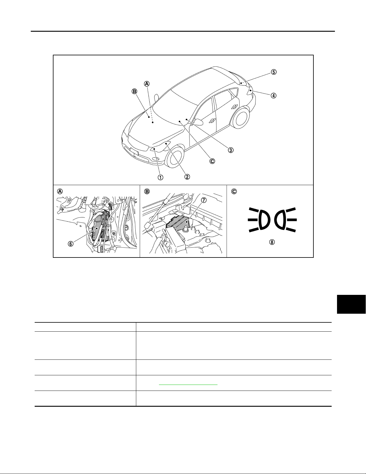
1. Parking lamp 2. Side marker lamp 3. Combination switch
4. Tail lamp and side marker lamp 5. License plate lamp 6. BCM
7. IPDM E/R 8. Tail lamp indicator lamp
A. Dash side lower (Passenger side) B. Engine room dash panel (RH) C. On the combination meter
Component Description INFOID:0000000003135283
Part Description
• Judges each switch condition by the combination switch reading function.
BCM
IPDM E/R
Combination switch
(Lighting & turn signal switch)
Combination meter
(Tail lamp indicator lamp)
• Judges the ON/OFF status of the clearance, license plate, side marker and tail
lamps according to the vehicle condition. Requests the tail lamp relay ON to IPDM
E/R (with CAN communication).
Controls the integrated relay and supplies voltage to the load according to the request
from BCM (with CAN communication).
Refer to BCS-8, "System Diagram"
Turns the tail lamp indicator lamp ON according to the request from BCM [with CAN
communication (through the unified meter and A/C amp.)].
.
H
I
J
K
EXL
M
N
O
P
EXL-29
Page 30
EXTERIOR LAMP BATTERY SAVER SYSTEM
Revision: 2007 November 2008 EX35
< FUNCTION DIAGNOSIS >
[XENON TYPE]
EXTERIOR LAMP BATTERY SAVER SYSTEM
System Diagram INFOID:0000000003135284
JPLIA0007GB
System Description INFOID:0000000003135285
OUTLINE
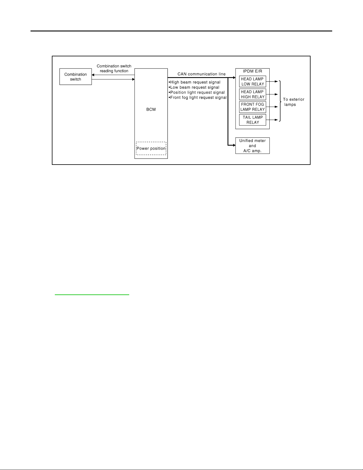
• Exterior lamp battery saver system is controlled by each function of BCM and IPDM E/R.
Control by BCM
- Combination switch reading function
- Headlamp control function
- Exterior lamp battery saver function
Control by IPDM E/R
- Relay control function
• BCM turns the exterior lamp* OFF after a period of time to prevent the battery from over-discharge when the
ignition switch is turned OFF with the exterior lamp ON.
*: Headlamp (LO/HI), parking lamp, tail lamp, side marker lamp, license plate lamp and front fog lamp
NOTE:
When the lighting switch is turned AUTO, the exterior lamp battery saver switches to the auto light system.
Refer to EXL-14, "System Diagram"
.
EXTERIOR LAMP BATTERY SAVER ACTIVATION
BCM activates the timer and turns the exterior lamp OFF 5 minutes after the ignition switch is turned from ON
→ OFF with the exterior lamps ON.
NOTE:
• Headlamp control function turns the exterior lamps ON normally when the ignition switch is turned ACC or
the engine started (both before and after the exterior lamp battery saver is turned OFF).
• The timer starts at the time that the lighting switch is turned from OFF → 1ST or 2ND with the exterior lamp
OFF.
EXL-30
Page 31
EXTERIOR LAMP BATTERY SAVER SYSTEM
Revision: 2007 November 2008 EX35
< FUNCTION DIAGNOSIS >
[XENON TYPE]
Component Parts Location INFOID:0000000003135286
A
B
C
D
E
F
G
JPLIA0948ZZ
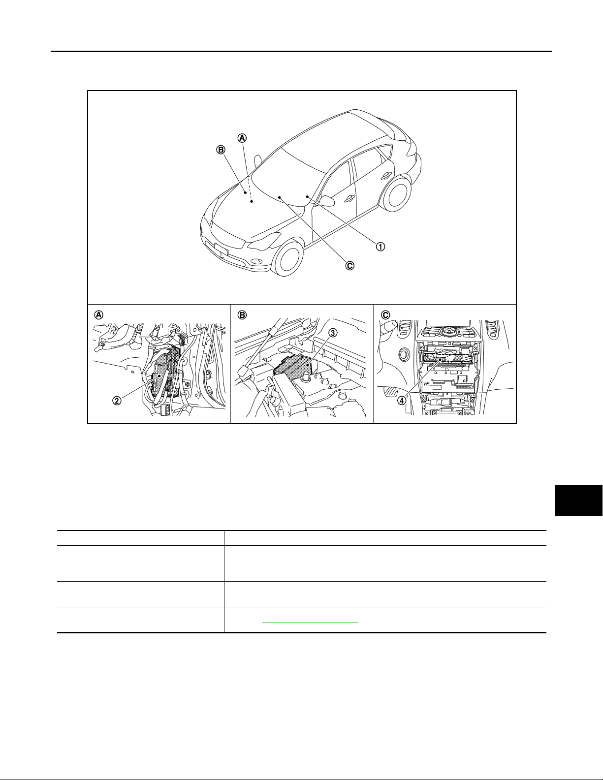
1. Combination switch 2. BCM 3. IPDM E/R
4. Unified meter and A/C amp.
A. Dash side lower (Passenger side) B. Engine room dash panel (RH) C. Behind the cluster lid C
Component Description INFOID:0000000003135287
Part Description
• Judges each switch condition by the combination switch reading function.
BCM
IPDM E/R
Combination switch
(Lighting & turn signal switch)
• Judges the exterior lamp OFF according to the vehi cle condit ion. Reques ts each relay OFF to IPDM E/R (with CAN communication).
Controls the integrated relay according to the request from BCM (with CAN communication).
Refer to BCS-8, "System Diagram"
.
H
I
J
K
EXL
M
N
O
EXL-31
P
Page 32

DIAGNOSIS SYSTEM (BCM)
Revision: 2007 November 2008 EX35
< FUNCTION DIAGNOSIS >
[XENON TYPE]
DIAGNOSIS SYSTEM (BCM)
COMMON ITEM
COMMON ITEM : CONSULT-III Function (BCM - COMMON ITEM) INFOID:0000000003784722
APPLICATION ITEM
CONSULT-III performs the following functions via CAN communication with BCM.
Diagnosis mode Function Description
Work Support Changes the setting for each system function.
Self Diagnostic Result Displays the diagnosis results judged by BCM.
CAN Diag Support Monitor
Data Monitor The BCM input/output signals are displayed.
Active Test The signals used to activate each device are forcibly supplied from BCM.
Ecu Identification The BCM part number is displayed.
Configuration
SYSTEM APPLICATION
BCM can perform the following functions for each system.
NOTE:
It can perform the diagnosis modes except the following for all sub system selection items.
System Sub system selection item
Door lock DOOR LOCK ×××
Rear window defogger REAR DEFOGGER ××
Warning chime BUZZER ××
Interior room lamp timer INT LAMP ×××
Exterior lamp HEAD LAMP ×××
Wiper and washer WIPER ××
Turn signal and hazard warning lamps FLASHER ×××
— AIR CONDITONER*
• Intelligent Key system
• Engine start system
Combination switch COMB SW ×
Body control system BCM ×
IVIS - NATS IMMU ××
Interior room lamp battery saver BATTERY SAVER ×××
— TRUNK* ××
Vehicle se curity system THEFT ALM ×××
RAP system RETAINED PWR ×
Signal buffer system SIGNAL BUFFER ××
TPMS TPMS (AIR PRESSURE MONITOR) ×××
Monitors the reception stat us of CAN communication viewed from BCM. Refer to CONSULT-III operation manual.
• Read and save the vehicle specification.
• Write the vehicle specification when replacing BCM.
×: Applicable item
Diagnosis mode
Work Support Data Monitor Active Test
INTELLIGENT KEY ×××
NOTE:
*: This item is displayed, but is not used.
FREEZE FRAME DATA (FFD) AND IGN COUNTER
Freeze Frame Data
EXL-32
Page 33
DIAGNOSIS SYSTEM (BCM)
Revision: 2007 November 2008 EX35
< FUNCTION DIAGNOSIS >
The BCM records the following condition at the moment a particular DTC is detected.
• Vehicle Speed
• Odd Trip Meter
• Vehicle Condition (BCM detected condition)
[XENON TYPE]
A
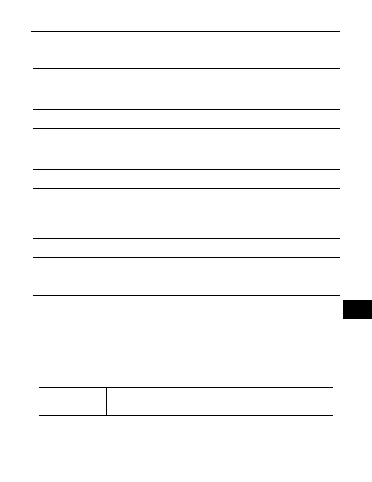
CONSULT screen terms Description
SLEEP>LOCK
SLEEP>OFF
LOCK>ACC While turning power supply position from “LOCK” to “ACC”
ACC>ON While turning power supply position from “ACC” to “IGN”
RUN>ACC
CRANK>RUN
RUN>URGENT While turning power supply position from “RUN“ to “ACC” (Emergency stop operation)
ACC>OFF While turning power supply position from “ACC” to “OFF”
OFF>LOCK While turning power supply position from “OFF” to “LOCK”
OFF>ACC While turning power supply position from “OFF” to “ACC”
ON>CRANK While turning power supply position from “IGN” to “CRANKING”
OFF>SLEEP
LOCK>SLEEP
LOCK Power supply position is “LOCK” (Ignition switch OFF with steering is locked.)
OFF Power supply position is “OFF” (Igni tion switch OFF with steering is unlocked.)
ACC Power supply position is “ACC” (Ignition switch ACC)
ON Power supply position is “IGN” (Ignition switch ON with engine stopped)
ENGINE RUN Power supply position is “RUN” (Ignition switch ON with engine running)
CRANKING Power supply position is “CRANKING” (At engine cranking)
While turning BCM status from low power consumption mode to normal mode (Power supply
position is “LOCK”)
While turning BCM status from low power consumption mode to normal mode (Power supply
position is “OFF”.)
While turning power supply position from “RUN” to “ACC” (Vehicle is stopping and selector
lever is except P position.)
While turning power supply position from “CRANKING” to “RUN” (From cranking up the engine to run it)
While turning BCM status from normal mode (Power supply position is “OFF”.) to low power
consumption mode
While turning BCM status from normal mode (Power supply position is “LOCK”.) t o low power consumption mode
B
C
D
E
F
G
H
I
J
K
IGN Counter
IGN counter indicates the number of times that ignition switch is turned ON after DTC is detected.
• The number is 0 when a malfunction is detected now.
• The number increases like 1 → 2 → 3...38 → 39 after returning to the normal condition whenever ignition
switch OFF → ON.
• The number is fixed to 39 until the self-diagnosis results are erased if it is over 39.
HEADLAMP
HEADLAMP : CONSULT-III Function (BCM - HEAD LAMP) INFOID:0000000003135289
WORK SUPPORT
Service item Setting item Setting
BATTERY SAVER SET
On* With the exterior lamp battery saver function
Off Without the exterior lamp battery saver function
EXL-33
EXL
M
N
O
P
Page 34
< FUNCTION DIAGNOSIS >
Revision: 2007 November 2008 EX35
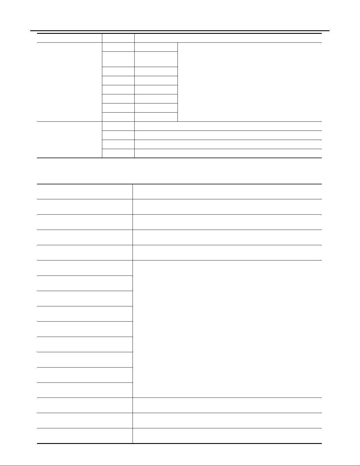
Service item Setting item Setting
ILL DELAY SET
CUSTOM A/LIGHT SETTING
*: Initial setting
DATA MONITOR
DIAGNOSIS SYSTEM (BCM)
[XENON TYPE]
MODE 1* 45 sec.
MODE 2
MODE 3 30 sec.
MODE 4 60 sec.
MODE 5 90 sec.
MODE 6 120 sec.
MODE 7 150 sec.
MODE 8 180 sec.
MODE 1* Normal
MODE 2 More sensitive setting than normal setting (Turns ON earlier than normal operation.)
MODE 3 More sensitive setting than MODE 2 (Turns O N earlier than MODE 2.)
MODE 4 Less sensitive setting than normal setting (Turns ON later than normal operation.)
Without the function
Sets delay timer function timer operation time.
(All doors closed)
Monitor item
[Unit]
PUSH SW
[On/Off]
ENGINE STATE
[Stop/Stall/Crank/Run]
VEH SPEED 1
[km/h]
KEY SW-SLOT
[On/Off]
TURN SIGNAL R
[On/Off]
TURN SIGNAL L
[On/Off]
TAIL LAMP SW
[On/Off]
HI BEAM SW
[On/Off]
HEAD LAMP SW1
[On/Off]
HEAD LAMP SW2
[On/Off]
PASSING SW
[On/Off]
AUTO LIGHT SW
[On/Off]
FR FOG SW
[On/Off]
RR FOG SW
[On/Off]
DOOR SW-DR
[On/Off]
DOOR SW-AS
[On/Off]
Description
The switch status input from push-button ignition switch
The engine status received from ECM with CAN communication
The value of the vehicle spee d received from unified meter and A/C amp. with CAN
communication
Key switch status input from key slot
Each switch status that BCM judges from the combination switch reading function
NOTE:
The item is indicated, but not monitored.
The switch status input from front door switch (driver side)
The switch status input from front door switch (passenger side)
EXL-34
Page 35
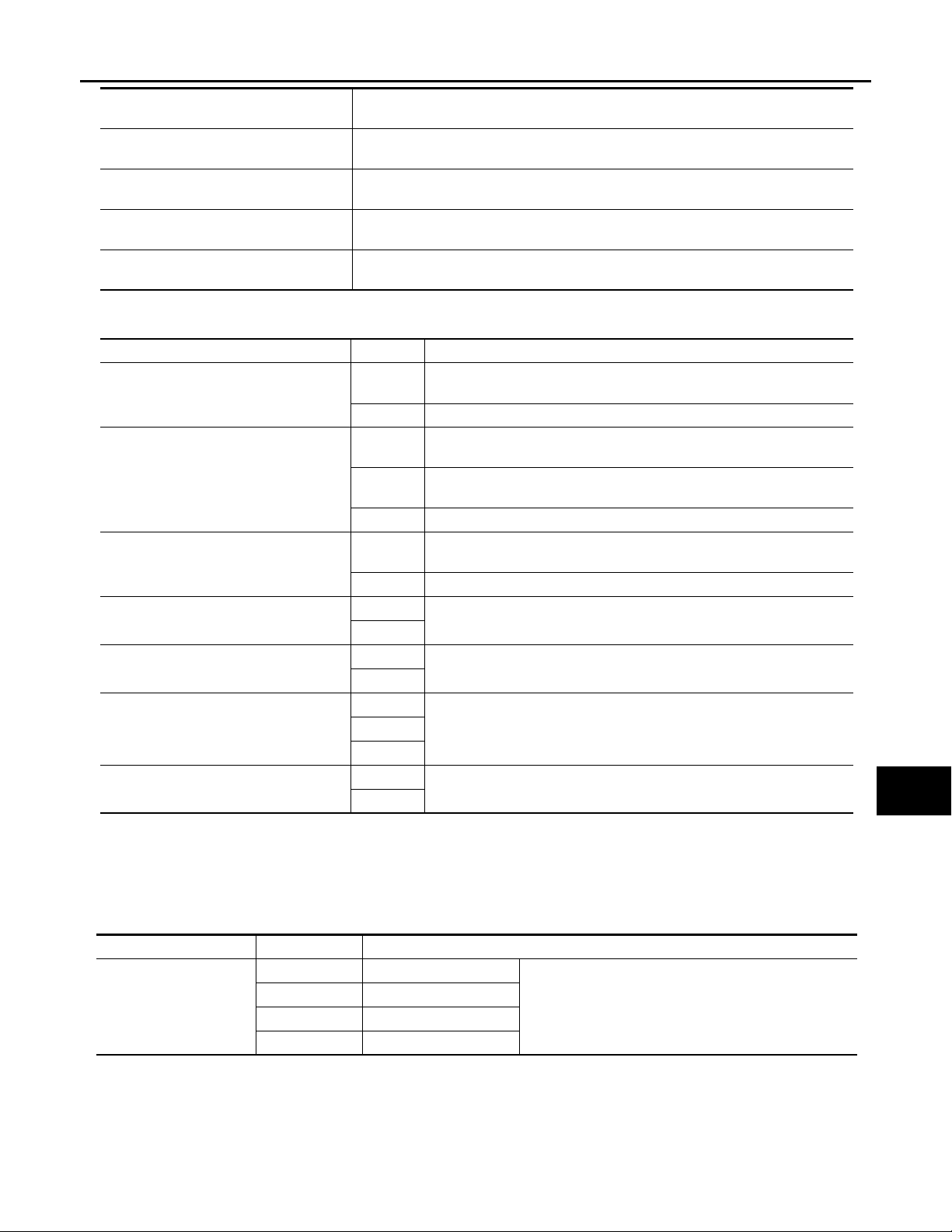
< FUNCTION DIAGNOSIS >
Revision: 2007 November 2008 EX35
DIAGNOSIS SYSTEM (BCM)
[XENON TYPE]
Monitor item
DOOR SW-RR
[On/Off]
DOOR SW- RL
[On/Off]
DOOR SW-BK
[On/Off]
OPTICAL SENSOR
[V]
ACTIVE TEST
Test item Operation Description
TAIL LA MP
HEAD LAMP
FR FOG LAMP
RR FOG LAMP
DA YTIME RUNNING LIG HT
CORNERING LAMP
ILL DIM SIGNAL
[Unit]
Description
The switch status input from rear door switch RH
The switch status input from rear door switch LH
NOTE:
The item is indicated, but not monitored.
The value of exterior brightne ss voltage input from the optical sensor
On
Off Stops the position light request signal transmission.
Hi
Low
Off Stops the high & low beam request signal transmission.
On
Off Stops the front fog light request signal transmission.
On
Off
On
Off
RH
LH
Off
On
Off
Transmits the position light request signal to IPDM E/R with CAN communication to turn the tail lamp ON.
Transmit s the high beam request signal with CAN communication to tu rn
the headlamp (HI).
Transmit s the low beam request signal with CAN communi cation to turn
the headlamp (LO).
Transmits the front fog light request signal to IPDM E/R with CAN communication to turn the front fog lamp ON.
NOTE:
The item is indicated, but cannot be tested.
NOTE:
The item is indicated, but cannot be tested.
NOTE:
The item is indicated, but cannot be tested.
NOTE:
The item is indicated, but cannot be tested.
A
B
C
D
E
F
G
H
I
J
K
EXL
FLASHER
FLASHER : CONSULT-III Function (BCM - FLASHER) INFOID:0000000003135290
WORK SUPPORT
Service item Setting item Setting
Lock Only* With locking only
HAZARD ANSWER
BACK
*: Initial setting
Unlk Only With unlocking only
Lock/Unlk With locking/unlocking
Off Without the function
Sets the hazard warning lamp answer back function
when the door is lock/unlock wi th the request switch or
the key fob.
DATA MONITOR
EXL-35
M
N
O
P
Page 36

< FUNCTION DIAGNOSIS >
Revision: 2007 November 2008 EX35
DIAGNOSIS SYSTEM (BCM)
[XENON TYPE]
REQ SW-DR
[On/Off]
REQ SW-AS
[On/Off]
PUSH SW
[On/Off]
TURN SIGNAL R
[On/Off]
TURN SIGNAL L
[On/Off]
HAZARD SW
[On/Off]
RKE-LOCK
[On/Off]
RKE-UNLOCK
[On/Off]
RKE-PANIC
[On/Off]
ACTIVE TEST
Monitor item
[Unit]
Description
The switch status input from the request switch (driver side)
The switch status input from the request switch (passenger side)
The switch status input from the push-button ignition switch
Each switch condition that BCM judges from the combination switch reading function
The switch status input from the hazard switch
Lock signal status received from the remote keyless entry receiver
Unlock signal status received from the remote keyless entry receiver
Panic alarm signal status received from the remote keyless entry receiver
FLASHER
Test item Operation Description
RH Outputs the voltage to blink the right side turn signal lamps.
LH Outputs the voltage to blink the left side turn signal lamps.
Off Stops the voltage to turn the turn signal lamps OFF.
EXL-36
Page 37
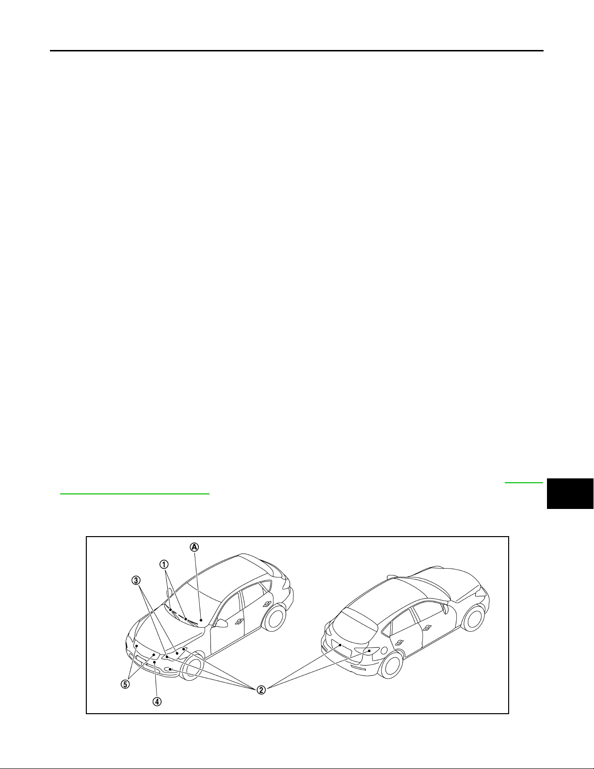
< FUNCTION DIAGNOSIS >
Revision: 2007 November 2008 EX35
DIAGNOSIS SYSTEM (IPDM E/R)
[XENON TYPE]
DIAGNOSIS SYSTEM (IPDM E/R)
Diagnosis Description INFOID:0000000003757032
AUTO ACTIVE TEST
Description
In auto active test mode, the IPDM E/R sends a drive signal to the following systems to check their operation.
• Oil pressure warning lamp
• Front wiper (LO, HI)
• Parking lamps
• License plate lamps
• Side maker lamps
• Tail lamps
• Front fog lamps
• Headlamps (LO, HI)
• A/C compressor (magnet clutch)
• Cooling fan (cooling fan control module)
Operation Procedure
1. Close the hood and lift the wiper arms from the windshield. (Prevent windshield damage due to wiper
operation)
NOTE:
When auto active test is performed with hood opened, sprinkle water on windshield beforehand.
2. Turn ignition switch OFF.
3. Turn the ignition switch ON, and within 20 seconds, press the driver door switch 10 times. Then turn the
ignition switch OFF.
CAUTION:
Close passenger door.
4. Turn the ignition switch ON within 10 seconds. After that the horn sounds once and the auto active test
starts.
5. The oil pressure warning lamp starts blinking when the auto active test starts.
6. After a series of the following operations is repeated 3 times, auto active test is completed.
NOTE:
When auto active test mode has to be cancelled halfway through test, turn ignition switch OFF.
CAUTION:
• If auto active test mode cannot be actuated, check door switch system. Refer to DLK-63,
"Component Function Check".
• Do not start the engine.
A
B
C
D
E
F
G
H
I
J
K
EXL
Inspection in Auto Active Test Mode
When auto active test mode is actuated, the following 5 steps are repeated 3 times.
JPMIA0950ZZ
EXL-37
M
N
O
P
Page 38
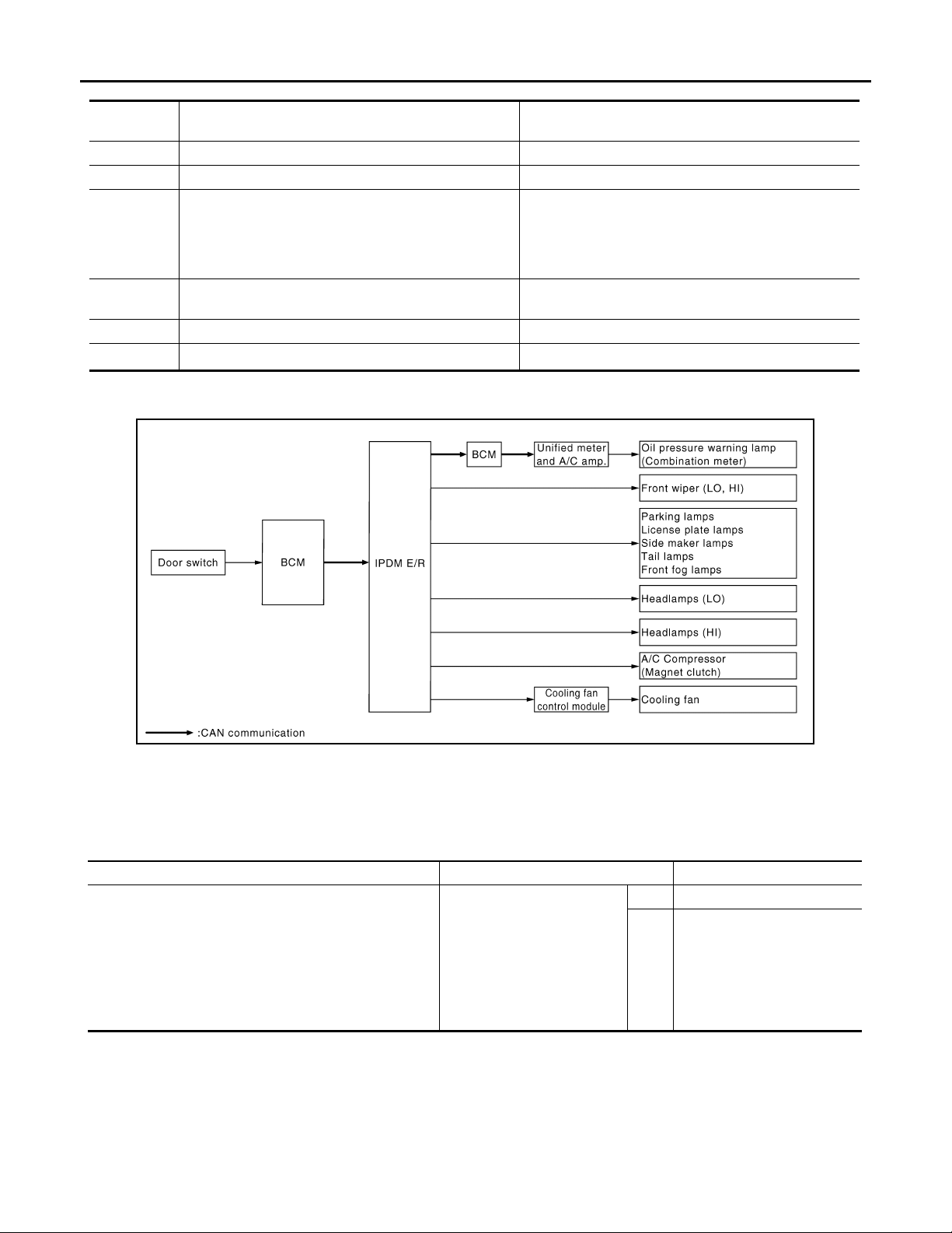
< FUNCTION DIAGNOSIS >
B
Revision: 2007 November 2008 EX35
DIAGNOSIS SYSTEM (IPDM E/R)
[XENON TYPE]
Operation
sequence
A Oil p ressure warning lamp Blinks continuously during operation of auto active test
1 Front wiper LO for 5 seconds → HI for 5 seconds
•Parking lamps
• License plate lamps
2
3 Headlamps
4 A/C compressor (magnet clutch) ON ⇔ OFF 5 times
*
5
*: Outputs duty ratio of 50% for 5 seconds → duty ratio of 100% for 5 seconds on the cooling fan control module.
• Side maker lamps
• Tail lamps
• Front fog lamps
Cooling fan MID for 5 seconds → HI for 5 seconds
Inspection location Operation
10 seconds
• LO 10 seconds
•HI ON ⇔ OFF 5 times
Concept of auto active test
JPMIA0009G
• IPDM E/R starts the auto active test with the door switch signals transmitted by BCM via CAN communication. Therefore, the CAN communication line between IPDM E/R and BCM is considered normal if the auto
active test starts successfully.
• The auto active test facilitates troubleshooting if any systems controlled by IPDM E/R cannot be operated.
Diagnosis chart in auto active test mode
Symptom Inspection contents Possible cause
Any of the following components do not operate
• Parking lamps
• License plate lamps
• Side maker lamps
•Tail lamps
•Front fog lamps
• Headlamp (HI, LO)
• Front wiper
Perform auto active test.
Does the applicable system
operate?
YES BCM signal input circuit
• Lamp or motor
• Lamp or motor ground circuit
• Harness or connector be-
NO
tween IPDM E/R and applicable system
•IPDM E/R
EXL-38
Page 39
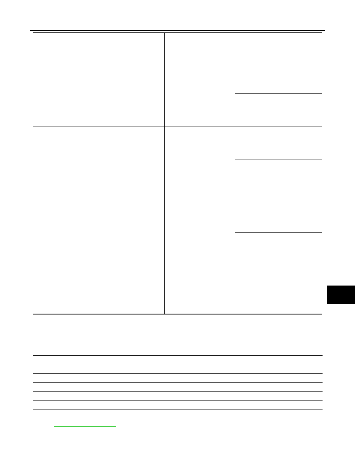
< FUNCTION DIAGNOSIS >
Revision: 2007 November 2008 EX35
DIAGNOSIS SYSTEM (IPDM E/R)
[XENON TYPE]
Symptom Inspection contents Possible cause
• Unified meter and A/C amp.
signal input circuit
• CAN communication signal
between unified meter and
A/C amp. and ECM
• CAN communication signal
between ECM and IPDM E/
R
• Magnet clutch
• Harness or connector between IPDM E/R and magnet clutch
• IPDM E/R
• Harness or connector between IPDM E/R and oil
pressure switch
• Oil pressure switch
• IPDM E/R
• CAN communication signal
between IPDM E/R and
BCM
• CAN communication signal
between BCM and unified
meter and A/C amp.
• Combination meter
• ECM signal input circuit
• CAN communication signal
between ECM and IPDM E/
R
• Cooling fan
• Harness or connector between cooling fan and cooling fan control module
• Cooling fan control module
• Harness or connector between IPDM E/R and cooling fan control module
• Cooling fan relay
• Harness or connector between IPDM E/R and cooling fan relay
• IPDM E/R
A/C compressor does not operate
Oil pressure warning lamp does not operate
Cooling fan does not operate
YES
Perform auto active test.
Does the magnet clutch operate?
NO
YES
Perform auto active test.
Does the oil pressure warning
lamp blink?
NO
YES
Perform auto active test.
Does the cooling fan oper ate ?
NO
CONSULT-III Function (IPDM E/R) INFOID:0000000003757033
A
B
C
D
E
F
G
H
I
J
K
EXL
M
APPLICATION ITEM
CONSULT-III performs the following functions via CAN communication with IPDM E/R.
Diagnosis mode Description
Ecu Identification Allows confirmation of IPDM E/R part number.
Self Diagnostic Result Displays the diagnosis results judged by IPDM E/R.
Data Monitor Displays the real-time input/output data from IPDM E/R input/output data.
Active Test IPDM E/R can provide a drive signal to electronic components to check their operations .
CAN Diag Support Monitor The results of transmit/r eceive diagnosis of CAN communication can be read.
SELF DIAGNOSTIC RESULT
Refer to EXL-167, "DTC Index".
DATA MONITOR
EXL-39
N
O
P
Page 40

< FUNCTION DIAGNOSIS >
Revision: 2007 November 2008 EX35
Monitor item
DIAGNOSIS SYSTEM (IPDM E/R)
[XENON TYPE]
Monitor Item
[Unit]
RAD FAN REQ
[%]
AC COMP REQ
[Off/On]
TAIL&CLR REQ
[Off/On]
HL LO REQ
[Off/On]
HL HI REQ
[Off/On]
FR FOG REQ
[Off/On]
FR WIP REQ
[Stop/1LOW/Low/Hi]
WIP AUTO STOP
[STOP P/ACT P]
WIP PROT
[Off/BLOCK]
IGN RLY1 -REQ
[Off/On]
IGN RLY
[Off/On]
PUSH SW
[Off/On]
INTER/NP SW
[Off/On]
ST RLY CONT
[Off/On]
IHBT RLY -REQ
[Off/On]
ST/INHI RLY
[Off/ ST /INHI/UNKWN]
DETENT SW
[Off/On]
S/L RLY -REQ
[Off/On]
S/L STATE
[LOCK/UNLOCK/UNKWN]
DTRL REQ
[Off]
OIL P SW
[Open/Close]
HOOD SW
[Off/On]
HL WASHER REQ
[Off]
THFT HRN REQ
[Off/On]
MAIN SIG-
NALS
×
×
×
×
×
×
×
× Displays the status of the front wiper auto stop signal judged by IPDM E/R.
× Displays the status of the front wiper fail-safe operation judged by IPDM E/R.
× Displays the status of the ignition relay judged by IPDM E/R.
Displays the value of the cooling fan speed signal received from ECM via CAN
communication.
Displays the status of the A/C compressor request signal received from ECM via
CAN communication.
Displays the status of the position light request signal received from BCM via CAN
communication.
Displays the status of the low beam request signal received from BCM via CAN
communication.
Displays the status of the high beam request signal received from BCM via CAN
communication.
Displays the status of the front fog light request signal received from BCM via
CAN communication.
Displays the status of the front wiper request signal received from BCM via CAN
communication.
Displays the status of the i gnition switch ON signal received from BCM via CAN
communication.
Displays the status of the push-button ignition switch judged by IPDM E/R.
Displays the status of the shift position judged by IPDM E/R.
Displays the status of t he starter relay status signal received from BCM vi a CAN
communication.
Displays the status of the starter control relay signal received from BCM via CAN
communication.
Displays the status of the starter relay and starter control relay judged by IPDM
E/R.
Displays the status of the control device (detention switch) judged by IPDM E/R.
Displays the status of the steering lock relay request received from BCM via CAN
communication.
Displays the status of the steering lock judged by IPDM E/R.
NOTE:
The item is indicated, but not monitored.
Displays the status of the oil pressure switch judged by IPDM E/R.
Displays the status of the hood switch judged by IPDM E/R.
NOTE:
The item is indicated, but not monitored.
Displays the status of the theft warning horn request signal received from BCM
via CAN communication.
Description
EXL-40
Page 41
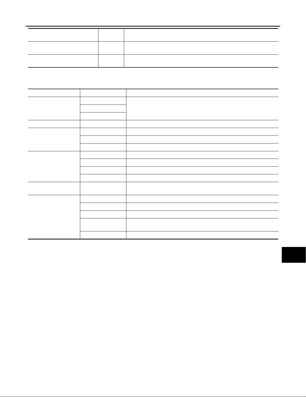
< FUNCTION DIAGNOSIS >
Revision: 2007 November 2008 EX35
DIAGNOSIS SYSTEM (IPDM E/R)
[XENON TYPE]
Monitor Item
[Unit]
HORN CHIRP
[Off/On]
CRNRNG LMP REQ
[Off]
MAIN SIG-
NALS
Description
Displays the status of the horn reminder s ignal receive d from BCM via CAN co mmunication.
NOTE:
The item is indicated, but not monitored.
ACTIVE TEST
Test item
Test item Operation Description
Off
CORNERING LAMP
HORN On Operates horn relay 1 and horn relay 2 for 20 ms.
FRONT WIPER
MOTOR F AN
HEAD LAMP WASHER On
EXTERNAL LAMPS
LH
RH
Off OFF
Lo Operates the front wiper relay.
Hi Operates the front wiper relay and fr ont wiper high relay.
1OFF
2 Outputs 50% pulse duty signal (PWM signal) to the cooling fan control module.
3 Outputs 80% pulse duty signal (PWM signal) to the cooling fan control module.
4 Outputs 100% pulse duty signal (PWM signal) to the cooling fan control module.
Off OFF
TAIL Operates the tail lamp relay.
Lo Operates the headlamp low relay.
Hi
Fog Operates the front fog lamp relay.
NOTE:
The item is indicated, but cannot be tested.
NOTE:
The item is indicated, but cannot be tested.
Operates the headlamp low re lay and ON/OFF the he adlamp high relay at 1 second intervals.
A
B
C
D
E
F
G
H
I
J
K
EXL-41
EXL
M
N
O
P
Page 42
DIAGNOSIS SYSTEM (AFS)
Revision: 2007 November 2008 EX35
< FUNCTION DIAGNOSIS >
[XENON TYPE]
DIAGNOSIS SYSTEM (AFS)
CONSULT-III Function (ADAPTIVE LIGHT) INFOID:0000000003135293
APPLICATION ITEM
Diagnostic mode Description
Ecu Identification Allows confirmation of auto levelizer control unit part number.
Self Diagnostic Result Displays the diagnosis results judged by AFS control unit.
Work support Sets each sensor.
Data monitor Indicates AFS control unit input data in real time.
Active test Provides the drive signal to the load. Checks operation.
WORK SUPPORT
Service item Description
ST ANG SEN ADJUSTMENT
LEVELIZER ADJUSTMENT
*: Adjusts the steering angle sensor neutral position on ABS actuator and electrical unit (control unit) side. Refer to BRC-8, "ADJUST-
MENT OF STEERING ANGLE SENSOR NEUTRAL POSITION : Special Repair Requirement".
*
Adjusts the height sensor si gnal out put valu e (AFS control unit reco gnized ) in the un loaded vehicle condition.
—
DATA MONITOR
Monitor item
[Unit]
STR ANGLS SIG
[deg]
VHCL SPD
[km/h]
SLCT LVR POSI
[P - 1]
HEAD LAMP
[On/Off]
AFS SW
[On/Off]
HI SEN OTP RR
[V]
LEV ACTR VLTG
[%]
SWVL SEN RH
[deg]
SWVL SEN LH
[deg]
SWVL ANGLE RH
[deg]
SWVL ANGLE LH
[deg]
*: The swivel angle "0°" (feedback value) of the swivel position sensor signal may differ from the swivel angle "0°" of the swivel motor
(AFS control unit command value). T his causes that the swivel motor initializes the value based on the step number from the stopper.
*
*
*
*
The steering angle value judged by the steering angle sensor signal received from
the steering angle sensor with CAN communication
The vehicle speed signal value from the unified meter and A/C amp. with CAN communication
The selector lever status judged by the position indicator signal received from TCM
with CAN communication
The headlamp On/Off st atus judged by the low beam he adlamp (ON) signal received
from IPDM E/R with CAN communication
The switch status input from AFS OFF switch
The height sensor signal voltage value input from the height sensor
The ratio value to the battery voltage generated by the levelizer activation signal con-
trol value judged by AFS control unit
The head lamp swivel angle value judged by AFS control unit received from the swivel position sensor signal input from the swivel actuator
The swivel angle command value to the swivel motor judged by AFS control unit
Description
ACTIVE TEST
CAUTION:
Start the engine when using “ACT IVE TEST”.
EXL-42
Page 43
< FUNCTION DIAGNOSIS >
Revision: 2007 November 2008 EX35
DIAGNOSIS SYSTEM (AFS)
[XENON TYPE]
Test item Operation Item Description
Origin Fast Swivels the right headlamp to the swivel angle 0° in the normal speed.
Peak Fast
LOW BEAM TEST RIGHT
LOW BEAM TEST LEFT
LEVELIZER TEST
NOTE:
“Fast” operation speed is as three times fast as “Slow”.
Origin Slow
Peak Slow
Origin Fast Swivels the left headlamp to the swivel angle 0° in the normal speed.
Peak Fast
Origin Slow
Peak Slow
Origin
Peak
Swivels the right headlamp to th e swivel angle app roximately 15° in the normal speed.
Swivels the right headlamp to the swivel angle 0° in the speed at the initialization.
Swivels the right headlamp to the swivel angle approximately 15° in the
speed at the initialization.
Swivels the left headlamp to the swivel angle approximately 17° in the normal speed.
Swivels the left headlamp to the swivel angle 0° in the speed at the initialization.
Swivels the left headlamp to the swivel angle approximately 17° in the speed
at the initialization.
Changes the aiming motor drive signal to approximately 70% of the battery
voltage. Moves the headlamp upward and downward.
Changes the aiming motor drive signal to approximately 15% of the battery
voltage. Moves the headlamp upward and downward.
A
B
C
D
E
F
G
H
I
J
K
EXL
M
N
O
P
EXL-43
Page 44

B2503, B2504 SWIVEL ACTUATOR
Revision: 2007 November 2008 EX35
< COMPONENT DIAGNOSIS >
[XENON TYPE]
COMPONENT DIAGNOSIS
B2503, B2504 SWIVEL ACTUATOR
Description INFOID:0000000003135294
SWIVEL ACTUATOR
The swivel actuator is installed in the headlamp unit. The swivel actuator consists of the swivel motor and the
swivel position sensor.
SWIVEL MOTOR
• The swivel motor is the two-phase step motor.
• The swivel motor drives headlamp by exciting the two drive coils according to the drive signal from AFS control unit.
• The rotation direction of the swivel motor is changeable by changing the exciting pattern.
SWIVEL POSITION SENSOR
The swivel position sensor detects the headlamp swivel angle to transmit the swivel position sensor signal to
AFS control unit.
DTC Logic INFOID:0000000003135295
DTC DETECTION LOGIC
• [B2503] Swivel actuator [RH]
• [B2504] Swivel actuator [LH]
DTC detection condition
AFS control unit indicates an applicable DTC when detecting any of the following conditions continuously for 2 seconds or more.
• AFS control unit-recognized swivel position differs extremely from the swivel
position sensor-input value while the swivel operating.
• The swivel position sensor signal does not change even though AFS control
unit transmits the swivel motor driving signal while the swivel operating
• The swivel motor short and open is detected while the swivel operating
• The swivel position sensor power supply is 6 V or more, or 4 V or less.
• The swivel position sensor signal is 0.25 V or less, or 4.75 V or more.
*: Initialization is not included.
*
DTC CONFIRMATION PROCEDURE
1.DTC ERASE
Erase the DTC memory of AFS with CONSULT-III.
>> GO TO 2.
2.CONFIRMATION DTC SELECTION
Select "B2503" or "B2504" for confirmation.
Which DTC is confirmation?
B2503 >> GO TO 3.
B2504 >> GO TO 4.
3.DTC CONFIRMATION (B2503)
*
.
*
.
DTC erase
condition
Ignition switch
OFF
Possible cause
Swivel position sensor
• Swivel position sensor
• Harness and connector
• AFS control unit
Swivel motor
•Swivel motor
• Harness and connector
• AFS control unit
1. Steer to the straight-forward position.
2. Start the engine.
3. Turn AFS OFF switch OFF.
4. Turn the headlamp ON.
5. Shift the selector lever to "N".
6. Steer to the right. (Rotate it once or more.)
7. Perform the self-diagnosis with CONSULT-III.
EXL-44
Page 45
B2503, B2504 SWIVEL ACTUATOR
Revision: 2007 November 2008 EX35
< COMPONENT DIAGNOSIS >
Is "B2503" detected?
YES >> Refer to EXL-45, "Diagnosis Procedure".
NO >> Refer to GI-38, "Intermittent Incident"
.
[XENON TYPE]
4.DTC CONFIRMATION (B2504)
1. Steer to the straight-forward position.
2. Start the engine.
3. Turn AFS OFF switch OFF.
4. Turn the headlamp ON.
5. Drive at 25 km/h (15.5 MPH) or more.
6. Steer to the left. (Rotate it once or more.)
7. Stop the vehicle.
8. Perform the self-diagnosis with CONSULT-III.
Is "B2504" detected?
YES >> Refer to EXL-45, "Diagnosis Procedure".
NO >> Refer to GI-38, "Intermittent Incident"
.
Diagnosis Procedure INFOID:0000000003135296
1.CHECK SWIVEL POSITION SENSOR SIGNAL INPUT
A
B
C
D
E
F
1. Turn the ignition switch ON.
2. Check the voltage between the AFS control unit harness connector and the ground.
Terminals
(+) (−)
AFS control unit
Connector Terminal
RH
LH 29
Is the measurement value within the standard value?
YES >> GO TO 2.
Less than the standard value >>GO TO 6.
Higher than the standard value>>GO TO 9.
M16
9
Ground
Voltage
(Approx.)
0.25 - 4.75 V
2.CHECK SWIVEL MOTOR
Check the swivel motor.EXL-48, "Component Inspection"
Is the inspection result normal?
YES >> GO TO 3.
NO >> Replace the front combination lamp.
.
3.CHECK SWIVEL MOTOR OPEN CIRCUIT
1. Turn the ignition switch OFF.
2. Disconnect AFS control unit connector and the headlamp swivel actuator connector.
3. Check continuity between the AFS control unit harness connector and the headlamp swivel actuator harness connector.
G
H
I
J
K
EXL
M
N
O
EXL-45
P
Page 46
B2503, B2504 SWIVEL ACTUATOR
Revision: 2007 November 2008 EX35
< COMPONENT DIAGNOSIS >
[XENON TYPE]
AFS control unit
Connector Terminal Connector Terminal
11
RH
M16
LH
13 7
32 3
34 4
15
17 4
36 8
38 7
Headlamp swivel
actuator
E29
E59
Continuity
8
3
Existed
Does continuity exist?
YES >> GO TO 4.
NO >> Repair the harnesses or connectors.
4.CHECK SWIVEL MOTOR SHORT CIRCUIT
Check continuity between the AFS control unit harness connector and the ground.
AFS control unit
Connector Terminal
RH
M16
LH
11
13
32
34
15
17
36
38
Ground
Continuity
Not existed
Does continuity exist?
YES >> Repair the harnesses or connectors.
NO >> GO TO 5.
5.CHECK SWIVEL MOTOR CIRCUIT VOLTAGE OUTPUT
1. Connect AFS control unit connector.
2. Turn the ignition switch ON.
3. Turn the headlamp ON.
4. Select “LOW BEAM TEST RIGHT” or “LOW BEAM TEST LEFT” of ADAPTIVE LIGHT active test item.
5. With operating the test item, check the voltage between the AFS control unit harness connector and the
ground.
EXL-46
Page 47
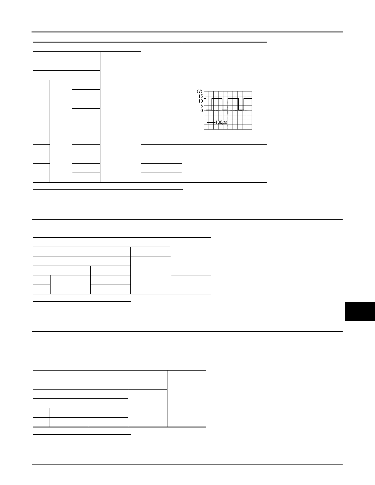
B2503, B2504 SWIVEL ACTUATOR
Revision: 2007 November 2008 EX35
< COMPONENT DIAGNOSIS >
[XENON TYPE]
Terminals
(+) (−)
AFS control unit
Connector Terminal
RH
LH
M16
RH
LH
11
32
15
36
13
34
17
38
Ground
Condition
Voltage
(Approx.)
Swivel motor
Active
SKIB2408J
8 - 12 V
9.5 - 11.5 V
Is the measurement value within the standard value?
YES >> Replace the front combination lamp.
NO >> Replace AFS control unit.
6.CHECK SWIVEL POSITION SENSOR SIGNAL OUTPUT
Check the voltage between the AFS control unit harness connector and the ground.
A
B
C
D
E
F
G
H
Terminals
(+) (−)
AFS control unit
Connector Terminal
RH
LH 24
M16
4
Ground
Voltage
(Approx.)
5 V
Is the measurement value normal?
YES >> GO TO 7.
NO >> GO TO 9.
7.CHECK SWIVEL POSITION SENSOR POWER SUPPLY CIRCUIT INPUT VOLTAGE
1. Turn the ignition switch OFF.
2. Disconnect the headlamp swivel actuator connector.
3. Turn the ignition switch ON.
4. Check the voltage between the headlamp swivel actuator harness connector and the ground.
Terminals
(+) (−)
Headlamp swivel actuator
Connector Terminal
RH E29 2
LH E59 2
Ground
Voltage
(Approx.)
5 V
Is the measurement value normal?
YES >> GO TO 8.
NO >> Repair the harnesses or connectors.
8.CHECK SWIVEL POSITION SENSOR SIGNAL SHORT CIRCUIT
I
J
K
EXL
M
N
O
P
EXL-47
Page 48
B2503, B2504 SWIVEL ACTUATOR
Revision: 2007 November 2008 EX35
< COMPONENT DIAGNOSIS >
1. Turn the ignition switch OFF.
2. Disconnect AFS control unit connector.
3. Check continuity between the AFS control unit harness connector and the headlamp swivel actuator harness connector.
[XENON TYPE]
AFS control unit Headlamp swivel actuator
Connector Terminal Connector Terminal
RH
LH 29 E59 1
M16
9E291
Continuity
Existed
Does continuity exist?
YES >> Replace the front combination lamp.
NO >> Repair the harnesses or connectors.
9.CHECK SWIVEL POSITION SENSOR GROUND CIRCUIT VOLTAGE OUTPUT
Check the voltage between the AFS control unit harness connector and the ground.
Terminals
(+) (−)
AFS control unit
Connector Terminal
RH
LH 27
M16
2
Ground
Voltage
(Approx.)
0 V
Is the measurement value normal?
YES >> GO TO 10.
NO >> Replace AFS control unit.
10.CHECK SWIVEL POSITION SENSOR SHORT GROUND CIRCUIT
1. Turn the ignition switch OFF.
2. Disconnect AFS control unit connector and the headlamp swivel actuator connector.
3. Check continuity between the AFS control unit harness connector and the headlamp swivel actuator harness connector.
AFS control unit Headlamp swivel actuator
Connector Terminal Connector Terminal
RH
LH 27 E59 6
M16
2E29 6
Continuity
Existed
Does continuity exist?
YES >> Replace the front combination lamp.
NO >> Repair the harnesses or connectors.
Component Inspection INFOID:0000000003135297
1.CHECK SWIVEL MOTOR SINGLE PART
1. Disconnect the swivel actuator connector.
2. Check the resistance among each swivel actuator connector terminal.
Swivel actuator
Terminal Terminal
3 7 7.2 Ω
4 8 7.2 Ω
3410 MΩ or more
Resistance
(Approx.)
EXL-48
Page 49

B2503, B2504 SWIVEL ACTUATOR
Revision: 2007 November 2008 EX35
< COMPONENT DIAGNOSIS >
Is the measurement value normal?
YES >> Swivel actuator is normal.
NO >> Replace the front combination lamp.
[XENON TYPE]
A
B
C
D
E
F
G
H
I
J
K
EXL
M
N
O
EXL-49
P
Page 50
B2514 HEIGHT SENSOR UNUSUAL [RR]
Revision: 2007 November 2008 EX35
< COMPONENT DIAGNOSIS >
[XENON TYPE]
B2514 HEIGHT SENSOR UNUSUAL [RR]
Description INFOID:0000000003135298
The height sensor is installed to the rear suspension arm. The height sensor detects the suspension arm displacement as the vehicle height change. The height sensor transmits the height sensor signal to AFS control
unit.
NOTE:
The sensor angle of the unloaded vehicle position is the reference value.
DTC Logic INFOID:0000000003135299
DTC DETECTION LOGIC
[B2514] Height sensor unusual [RR]
DTC detection condition DTC erase condition Possib le ca use
An applicable DTC is indicated when any of the following
conditions is detected continuously for 2 seconds or more.
• The height sensor power supply is 6 V or more, or 4 V or
less.
• The height sensor signal is 0.25 V or less , or 4.75 V or
more.
Ignition switch OFF
Height sensor
• Height sensor
• Harness and connector
• AFS control unit
DTC CONFIRMATION PROCEDURE
1.DTC ERASE
Erase the DTC memory of AFS with CONSULT-III.
>> GO TO 2.
2.DTC CONFIRMATION
1. Start the engine.
2. Turn the headlamp ON.
3. Select the self-diagnosis with CONSULT-III.
4. Check the self-diagnosis result. Refer to EXL-178, "DTC Index"
Is "B2514" detected?
YES >> Refer to EXL-50, "Diagnosis Procedure".
NO >> Refer to GI-38, "Intermittent Incident"
.
.
Diagnosis Procedure INFOID:0000000003135300
1.CHECK HEIGHT SENSOR POWER SUPPLY OUTPUT
1. Turn the ignition switch ON.
2. Check the voltage between the AFS control unit harness connector and the ground.
Terminals
(+) (−)
AFS control unit
GroundConnector Terminal
M16 6 5 V
Is the measurement value within the standard value?
YES >> GO TO 2.
NO >> Replace AFS control unit.
Voltage
(Approx.)
2.CHECK HEIGHT SENSOR POWER SUPPLY INPUT
Check the voltage between the AFS control unit harness connector and the ground.
EXL-50
Page 51
B2514 HEIGHT SENSOR UNUSUAL [RR]
Revision: 2007 November 2008 EX35
< COMPONENT DIAGNOSIS >
[XENON TYPE]
Terminals
(+) (−)
AFS control unit
GroundConnector Terminal
M16 28 0.25 - 4.75 V
Voltage
(Approx.)
Is the measurement value within the standard value?
YES >> Replace AFS control unit.
Less than the standard value >>GO TO 3.
Higher than the standard value>>GO TO 6.
3.CHECK HEIGHT SENSOR POWER SUPPLY CIRCUIT OUTPUT VOLTAGE
1. Turn the ignition switch OFF.
2. Disconnect the height sensor connector.
3. Turn the ignition switch ON.
4. Check the voltage between the height sensor harness connector and the ground.
Terminals
(+) (−)
Height sensor
GroundConnector Terminal
B32 1 5 V
Voltage
(Approx.)
Is the measurement value within the standard value?
YES >> GO TO 4.
NO >> Repair the harnesses or connectors.
4.CHECK HEIGHT SENSOR SIGNAL OPEN CIRCUIT
A
B
C
D
E
F
G
H
I
1. Turn the ignition switch OFF.
2. Disconnect AFS control unit connector.
3. Check continuity between the AFS control unit harness connector and the height sensor harness connector.
AFS control unit Height sensor
Connector Terminal Connector Terminal
M16 28 B32 2 Existed
Continuity
Does continuity exist?
YES >> GO TO 5.
NO >> Repair the harnesses or connectors.
5.CHECK HEIGHT SENSOR SIGNAL SHORT CIRCUIT
Check continuity between the height sensor harness connector and the ground.
Height sensor
Connector Terminal
B32 2 Not existed
Ground
Continuity
Does continuity exist?
YES >> Repair the harnesses or connectors.
NO >> Replace the height sensor.
6.CHECK HEIGHT SENSOR GROUND
J
K
EXL
M
N
O
P
Check the voltage between the AFS control unit harness connector and the ground.
EXL-51
Page 52
B2514 HEIGHT SENSOR UNUSUAL [RR]
Revision: 2007 November 2008 EX35
< COMPONENT DIAGNOSIS >
Terminals
(+) (−)
AFS control unit
GroundConnector Terminal
M16 8 0 V
Voltage
(Approx.)
Is the measurement value within the standard value?
YES >> GO TO 7.
NO >> Replace AFS control unit.
[XENON TYPE]
7.CHECK HEIGHT SENSOR GROUND CIRCUIT
1. Turn the ignition switch OFF.
2. Disconnect AFS control unit connector and the height sensor connector.
3. Check continuity between the AFS control unit harness connector and the height sensor harness connector.
AFS control unit Height sensor
Connector Terminal Connector Terminal
M16 8 B32 3 Existed
Continuity
Does continuity exist?
YES >> Replace the height sensor.
NO >> Repair the harnesses or connectors.
Component Inspection INFOID:0000000003135301
1.CHECK HEIGHT SENSOR
1. Remove the height sensor (the height sensor connector is connected).
2. Start the engine.
3. Turn the light switch 2ND.
4. Select "HI SEN OTP RR” of AFS data monitor item.
5. With moving the sensor lever, check the monitor status.
Monitor status
Monitor item Cond iti on
Contact with
stopper
HI SEN OTP RR
Sensor lever position
Moving between two positions
90° from stopper 4.5 V
Is the output value normal?
YES >> Height sensor is normal.
NO >> Replace the height sensor.
[Stand ard value
(Approx.)]
0.9 V
Smooth movement
EXL-52
Page 53
< COMPONENT DIAGNOSIS >
Revision: 2007 November 2008 EX35
B2516 SHIFT SIGNAL [P, R]
[XENON TYPE]
B2516 SHIFT SIGNAL [P, R]
Description INFOID:0000000003135302
AFS control unit receives the shift position signal from TCM with CAN communication.
DTC Logic INFOID:0000000003135303
DTC DETECTION LOGIC
[B2516] Shift signal [P, R]
DTC detection condition DTC erase condition Possible causes
The shift position signal is not received. Ignition switch OFF
DTC CONFIRMATION PROCEDURE
•TCM
•AFS control unit
1.DTC ERASE
Erase the DTC memory of AFS with CONSULT-III.
>> GO TO 2.
2.DTC CONFIRMATION
1. Turn ignition ON.
2. Select the self-diagnosis with CONSULT-III.
3. Check the self-diagnosis result. Refer to EXL-178, "DTC Index"
“B2516” detected?
Is
YES >> Refer to EXL-53, "Diagnosis Procedure".
NO >> Refer to GI-38, "Intermittent Incident"
.
.
A
B
C
D
E
F
G
H
I
Diagnosis Procedure INFOID:0000000003135304
1.TCM SELF-DIAGNOSIS
Check the self-diagnosis result with CONSULT-III. Check that TCM does not detect any DTCs.
Is any DTC detected?
YES >> Check TCM. Refer to TM-104, "Reference Value".
NO >> GO TO 2.
2.DTC ERASE
Erase the DTC memory of AFS with CONSULT-III.
Is the memory erased?
YES >> Inspection end.
NO >> Replace AFS control unit.
J
K
EXL
M
N
O
P
EXL-53
Page 54
B2517 VEHICLE SPEED SIGNAL
Revision: 2007 November 2008 EX35
< COMPONENT DIAGNOSIS >
[XENON TYPE]
B2517 VEHICLE SPEED SIGNAL
Description INFOID:0000000003135305
AFS control unit receives the vehicle speed signal from the unified meter and A/C amp. with CAN communication.
DTC Logic INFOID:0000000003135306
DTC DETECTION LOGIC
[B2517] Vehicle speed signal
DTC detection condition DTC erase condition Possible causes
• Unified meter and A/C
The vehicle speed signal is not received. Ignition switch OFF
DTC CONFIRMATION PROCEDURE
amp.
•AFS control unit
1.DTC ERASE
Erase the DTC memory of AFS with CONSULT-III.
>> GO TO 2.
2.DTC CONFIRMATION
1. Turn ignition ON.
2. Select the self-diagnosis with CONSULT-III.
3. Check the self-diagnosis result. Refer to EXL-178, "DTC Index"
Is
“B2517” detected?
YES >> Refer to EXL-54, "Diagnosis Procedure".
NO >> Refer to GI-38, "Intermittent Incident"
.
.
Diagnosis Procedure INFOID:0000000003135307
1.UNIFIED METER AND A/C AMP. SELF-DIAGNOSIS
Check the self-diagnosis result with CONSULT-III. Check that the unified meter and A/C amp. does not detect
any DTCs.
Is any DTC detected?
YES >> Check the unified meter and A/C amp. Refer to MWI-101, "DTC Index".
NO >> GO TO 2.
2.DTC ERASE
Erase the DTC memory of AFS with CONSULT-III.
Is the memory erased?
YES >> Inspection end.
NO >> Replace AFS control unit.
EXL-54
Page 55
< COMPONENT DIAGNOSIS >
Revision: 2007 November 2008 EX35
B2519 LEVELIZER CALIBRATION
[XENON TYPE]
B2519 LEVELIZER CALIBRATION
Description INFOID:0000000003135308
AFS control unit transmits the height sensor signal from the height sensor.
DTC Logic INFOID:0000000003135309
[B2519] Levelizer calibration
DTC detection condition DTC erase condition Possible causes
The height sensor adjustment position is not recognized.
When the levelizer adjustment is completed
AFS control unit
Diagnosis Procedure INFOID:0000000003135310
1.LEVELIZER ADJUSTMENT
Perform the levelizer adjustment.
>> Refer to EXL-9, "LEVELIZER ADJUSTMENT : Special Repair Requirement"
.
A
B
C
D
E
F
G
H
I
J
K
EXL
M
N
O
P
EXL-55
Page 56
B2521 ECU CIRCUIT
Revision: 2007 November 2008 EX35
< COMPONENT DIAGNOSIS >
[XENON TYPE]
B2521 ECU CIRCUIT
Description INFOID:0000000003135311
AFS control unit judges the vehicle condition from each signal. AFS control unit controls AFS function and the
headlamp aiming.
DTC Logic INFOID:0000000003135312
DTC DETECTION LOGIC
[B2521] ECU circuit
Error detection condition DTC erase condition Possible cause
• AFS control unit indicates an applicable DTC when detecting any of the following conditions continuously for 2
seconds or more.
- The swivel position sensor is shorted to the power supply
or the ground.
- The swivel position sensor signal is shorted to the
ground.
- The height sensor power supply is shorted to the power
supply or the ground.
- The height sensor sig na l is sh orte d to the groun d.
• AFS control unit RAM/ROM error
Ignition switch OFF
Swivel position sensor
• Swivel position sensor
• Harness and connector
• AFS control unit
Height sensor
• Height sensor
• Harness and connector
• AFS control unit
AFS control unit (RAM/ROM)
• AFS control unit
DTC CONFIRMATION PROCEDURE
1.DTC ERASE
Erase the DTC memory of AFS with CONSULT-III.
>> GO TO 2.
2.DTC CONFIRMATION PROCEDURE
1. Turn ignition ON.
2. Select the self-diagnosis with CONSULT-III.
3. Check the self-diagnosis result. Refer to EXL-178, "DTC Index"
Is
“B2521” detected?
.
YES >> Refer to EXL-56, "Diagnosis Procedure".
NO >> Refer to GI-38, "Intermittent Incident"
.
Diagnosis Procedure INFOID:0000000003135313
1.CHECK EACH SENSOR POWER SUPPLY
1. Turn the ignition switch ON.
2. Check the voltage between the AFS control unit harness connector and the ground.
Terminals
(+) (−)
AFS control unit
Connector Terminal
4
M16
24
Ground
Is the measurement value within the standard value?
YES >> GO TO 2.
Less than the standard value >>GO TO 3.
Higher than the standard value>>GO TO 4.
Voltage
(Approx.)
5 V6
EXL-56
Page 57
< COMPONENT DIAGNOSIS >
Revision: 2007 November 2008 EX35
B2521 ECU CIRCUIT
[XENON TYPE]
2.CHECK EACH SENSOR SIGNAL
Check the voltage between the AFS control unit harness connector and the ground.
Terminals
(+) (−)
AFS control unit
Connector Terminal
9
M16
29
Ground
Voltage
(Approx.)
0.25 - 4.75 V28
Is the measurement value within the standard value?
YES >> Replace AFS control unit.
Less than the standard value >>GO TO 5.
Higher than the standard value>>GO TO 6.
3.CHECK EACH SENSOR POWER SUPPLY SHORT CIRCUIT
1. Turn the ignition switch OFF.
2. Disconnect AFS control unit connector.
3. Check continuity between the AFS control unit harness connector and the ground.
AFS control unit
Connector Terminal
4
M16
24
Ground
Continuity
Not existed6
Does continuity exist?
YES >> Repair the harnesses or connectors.
NO >> Replace AFS control unit.
4.CHECK EACH SENSOR POWER SUPPLY CIRCUIT
1. Turn the ignition switch OFF.
2. Disconnect AFS control unit connector.
3. Check the voltage between the AFS control unit harness connector and the ground.
A
B
C
D
E
F
G
H
I
J
K
EXL
Terminals
(+) (−)
AFS control unit
Connector Terminal
4
M16
24
Ground
Voltage
(Approx.)
0 V6
Is the measurement value normal?
YES >> Replace AFS control unit.
NO >> Repair the harnesses or connectors.
5.CHECK EACH SENSOR SIGNAL SHORT CIRCUIT
1. Turn the ignition switch OFF.
2. Disconnect AFS control unit connector.
3. Check continuity between the AFS control unit harness connector and the ground.
EXL-57
M
N
O
P
Page 58
< COMPONENT DIAGNOSIS >
Revision: 2007 November 2008 EX35
B2521 ECU CIRCUIT
[XENON TYPE]
AFS control unit
Connector Terminal
9
M16
29
Ground
Continuity
Not existed28
Does continuity exist?
YES >> Repair the harnesses or connectors.
NO >> Replace AFS control unit.
6.CHECK EACH SENSOR SIGNAL SHORT CIRCUIT
1. Turn the ignition switch OFF.
2. Disconnect AFS control unit connector.
3. Turn the ignition switch ON.
4. Check the voltage between the AFS control unit harness connector and the ground.
Terminals
(+) (−)
AFS control unit
Connector Terminal
9
M16
29
Ground
Is the measurement value normal?
YES >> Replace AFS control unit.
NO >> Repair the harnesses or connectors.
Voltage
(Approx.)
0 V28
EXL-58
Page 59
C0126 STEERING ANGLE SENSOR SIGNAL
Revision: 2007 November 2008 EX35
< COMPONENT DIAGNOSIS >
[XENON TYPE]
C0126 STEERING ANGLE SENSOR SIGNAL
Description INFOID:0000000003135314
AFS control unit receives the steering angle sensor signal from the steering angle sensor with CAN communication.
DTC Logic INFOID:0000000003135315
DTC DETECTION LOGIC
[C0126] Steering angle sensor signal
DTC detection condition DTC erase condition Possible causes
In any of the following conditions
• The steering angle sensor signal is not received.
• The steering angle sensor signal error is received.
• Out-of-standard signal (-900°- +900°) is received.
DTC CONFIRMATION PROCEDURE
The ignition switch OFF
• Steering angle sensor
•AFS control unit
1.DTC ERASE
Erase the DTC memory of AFS with CONSULT-III.
>> GO TO 2.
2.DTC CONFIRMATION
A
B
C
D
E
F
G
H
1. Start the engine.
2. Turn the steering wheel to the maximum right/left.
3. Select the self-diagnosis with CONSULT-III.
4. Check the self-diagnosis result. Refer to EXL-178, "DTC Index"
Is
“C0126” detected?
YES >> Refer to EXL-59, "Diagnosis Procedure".
NO >> Refer to GI-38, "Intermittent Incident".
.
Diagnosis Procedure INFOID:0000000003135316
1.ABS ACTUA TOR AND ELECTRICAL UNIT (CONTROL UNIT) SELF-DIAGNOSIS
Check the self-diagnosis result with CONSULT-III. Check that ABS actuator and electrical unit (control unit)
does not detect any DTCs.
Is any DTC detected?
YES >> Check ABS actuator and electrical unit (control unit).Refer to BRC-95, "DTC No. Index".
NO >> GO TO 2.
2.DTC ERASE
Erase DTC memory of AFS with CONSULT-III.
Is the memory erased?
YES >> Inspection end.
NO >> Replace AFS control unit.
I
J
K
EXL
M
N
O
EXL-59
P
Page 60
C0428 STEERING ANGLE SENSOR CALIBRATION
Revision: 2007 November 2008 EX35
< COMPONENT DIAGNOSIS >
[XENON TYPE]
C0428 STEERING ANGLE SENSOR CALIBRATION
Description INFOID:0000000003135317
AFS control unit receives the steering angle sensor signal from the steering angle sensor with CAN communication.
DTC Logic INFOID:0000000003135318
[C0428] Steering angle sensor calibration
DTC detection condition DTC erase condition Possible causes
The steering angle sensor neutral position is not recognized.
When the steering angle sensor
neutral position registration is
completed
Steering angl e sensor
Diagnosis Procedure INFOID:0000000003135319
1.STEERING ANGLE SENSOR NEUTRAL POSITION ADJUSTMENT
Perform the steering angle sensor neutral position adjustment.
CAUTION:
Perform the steering angle sensor neutral position adjustment on VDC side. VDC may activate incorrectly.
>> Refer to BRC-8, "ADJUSTMENT OF STEERING ANGLE SENSOR NEUTRAL P OSITION : Spe-
cial Repair Requirement".
EXL-60
Page 61
< COMPONENT DIAGNOSIS >
Revision: 2007 November 2008 EX35
U1000 CAN COMM CIRCUIT
[XENON TYPE]
U1000 CAN COMM CIRCUIT
Description INFOID:0000000003135320
CAN (Controller Area Network) is the serial transmission for real time application. CAN is the multiplex communication for the vehicle with superior data transmission speed and error detection ability. Many electronic
control units are equipped on the vehicle. These control units do not operate individually, but associates with
other control units by sharing information. In CAN communication, each control unit is connected with two
communication lines (CAN-H and CAN-L). Much information is transmitted with fewer communication lines
than before. Each control unit transmits/receives data and reads the necessary data only.
CAN Communication Signal Chart. Refer to LAN-27, "CAN Communication Signal Chart"
.
DTC Logic INFOID:0000000003135321
DTC DETECTION LOGIC
[U1000] CAN communication circuit
DTC detection condition DTC erase condition Possible causes
When AFS control unit does not transmit/receive CAN communication signal continuously for 2 seconds or more
Ignition switch OFF CAN communication system
Diagnosis Procedure INFOID:0000000003135322
1.PERFORM SELF DIAGNOSTIC
1. Turn ignition switch ON and wait for 2 seconds or more.
2. Check “Self Diagnostic Result”.
Is
“CAN COMM CIRCUIT” displayed?
YES >> Refer to LAN-18, "Trouble Diagnosis Flow Chart".
NO >> Refer to GI-38, "Intermittent Incident"
.
A
B
C
D
E
F
G
H
I
J
K
EXL
M
N
O
P
EXL-61
Page 62
U1010 CONTROL UNIT (CAN)
Revision: 2007 November 2008 EX35
< COMPONENT DIAGNOSIS >
[XENON TYPE]
U1010 CONTROL UNIT (CAN)
DTC Logic INFOID:0000000003596964
DTC DETECTION LOGIC
[U1000] CAN communication circuit
DTC
U1010 CONTROL UNIT (CAN) AFS control unit detected internal CAN communication circuit malfunction. AFS control unit
CONSULT-III display
description
DTC detection condition Possible causes
Diagnosis Procedure INFOID:0000000003596965
1.REPLACE AFS CONTROL UNIT
When DTC [U1010] is detected, replace AFS control unit.
>> Replace AFS control unit.
EXL-62
Page 63
POWER SUPPLY AND GROUND CIRCUIT
Revision: 2007 November 2008 EX35
< COMPONENT DIAGNOSIS >
[XENON TYPE]
POWER SUPPLY AND GROUND CIRCUIT
BCM (BODY CONTROL MODULE)
BCM (BODY CONTROL MODULE) : Diagnosis Procedure INFOID:0000000003757034
1.CHECK FUSE AND FUSIBLE LINK
Check that the following fuse and fusible link are not blown.
Signal name Fuse and fusible link No.
Battery power supply
Is the fuse fusing?
YES >> Replace the blown fuse or fusible link after repairing the affected circuit if a fuse or fusible link is
blown.
NO >> GO TO 2.
K
10
2.CHECK POWER SUPPLY CIRCUIT
1. Turn ignition switch OFF.
2. Disconnect BCM connectors.
3. Check voltage between BCM harness connector and ground.
Terminals
(+) (−)
BCM
Connector Terminal
M118 1
M119 11
Is the measurement value normal?
YES >> GO TO 3.
NO >> Repair harness or connector.
Ground
Voltage
(Approx.)
Battery voltage
3.CHECK GROUND CIRCUIT
A
B
C
D
E
F
G
H
I
J
K
Check continuity between BCM harness connector and ground.
BCM
Connector Terminal
M119 13 Existed
Does continuity exist?
YES >> INSPECTION END
NO >> Repair harness or connector.
Ground
Continuity
IPDM E/R (INTELLIGENT POWER DISTRIBUTION MODULE ENGINE ROOM)
IPDM E/R (INTELLIGENT POWER DISTRIBUTION MODULE ENGINE ROOM) : Diagnosis Procedure
INFOID:0000000003757035
1.CHECK FUSES AND FUSIBLE LINK
Check that the following IPDM E/R fuses or fusible links are not blown.
EXL-63
EXL
M
N
O
P
Page 64
POWER SUPPLY AND GROUND CIRCUIT
Revision: 2007 November 2008 EX35
< COMPONENT DIAGNOSIS >
Signal name Fuses and fusible link No.
C
Battery power supply
50
51
Is the fuse fusing?
YES >> Replace the blown fuse or fusible link after repairing the affected circuit if a fuse or fusible link is
blown.
NO >> GO TO 2.
[XENON TYPE]
2.CHECK POWER SUPPLY CIRCUIT
1. Turn ignition switch OFF.
2. Disconnect IPDM E/R connector.
3. Check voltage between IPDM E/R harness connector and ground.
Terminals
(+)
IPDM E/R
Connector Terminal
E4 1 Battery voltage
(−)
Ground
Voltage
(Approx.)
Is the measurement value normal?
YES >> GO TO 3.
NO >> Repair harness or connector.
3.CHECK GROUND CIRCUIT
Check continuity between IPDM E/R harness connectors and ground.
IPDM E/R
Connector Terminal
E5 12
E6 41
Ground
Continuity
Existed
Does continuity exist?
YES >> INSPECTION END
NO >> Repair harness or connector.
AFS CONTROL UNIT
AFS CONTROL UNIT : Diagnosis Procedure INFOID:0000000003135326
1.FUSE INSPECTION
Check that the following fuses are not fusing.
Signal name Connection position Fuse No. Capacity
Ignition power supply FUSE BLOCK (J/B) 3 10 A
Is the fuse fusing?
YES >> Repair the applicable circuit. And then replace the fuse.
NO >> GO TO 2.
2.CHECK POWER SUPPLY CIRCUIT
1. Turn ignition switch OFF.
2. Disconnect AFS control unit harness connector.
3. Turn ignition switch ON.
4. Check voltage between AFS control unit harness connector and ground.
EXL-64
Page 65
POWER SUPPLY AND GROUND CIRCUIT
Revision: 2007 November 2008 EX35
< COMPONENT DIAGNOSIS >
[XENON TYPE]
Terminals
(+) (−)
AFS control unit
GroundConnector Terminal
M16 1 Battery voltage
Voltage
(Approx.)
Is the measurement value normal?
YES >> GO TO 3.
NO >> Repair harness or connector.
3.CHECK GROUND CIRCUIT
1. Turn ignition switch OFF.
2. Check continuity between AFS control unit harness connectors and ground.
AFS control unit
Connector Terminal
M16 25 Existed
Ground
Does continuity exist?
YES >> Power supply and ground circuit are normal.
NO >> Repair harness or connector.
Continuity
A
B
C
D
E
F
G
H
I
J
K
EXL
M
N
O
P
EXL-65
Page 66
EXTERIOR LAMP FUSE
Revision: 2007 November 2008 EX35
< COMPONENT DIAGNOSIS >
[XENON TYPE]
EXTERIOR LAMP FUSE
Description INFOID:0000000003135327
Fuse list
Unit Location Fuse No. Capacity
Headlamp HI (LH) IPDM E/R #54 10 A
Headlamp HI (RH) IPDM E/R #55 10 A
Headlamp LO (LH) IPDM E/R #56 15 A
Headlamp LO (RH) IPDM E/R #57 15 A
Front fog lamp IPDM E/R #58 15 A
• Parking lamp
• Front side marker lamp
• Tail lamp
• Rear side marker lamp
• License plate lamp
• Each illumination
Stop lamp FUSE BLOCK (J/B) #7 10 A
Back-up lamp FUSE BLOCK (J/B) #4 10 A
IPDM E/R #52 10 A
IPDM E/R #53 10 A
Diagnosis Procedure INFOID:0000000003135328
1.CHECK FUSE
Check that the following fuses are not fusing.
Unit Location Fuse No. Capacity
Headlamp HI (LH) IPDM E/R #54 10 A
Headlamp HI (RH) IPDM E/R #55 10 A
Headlamp LO (LH) IPDM E/R #56 15 A
Headlamp LO (RH) IPDM E/R #57 15 A
Front fog lamp IPDM E/R #58 15 A
•Parking lamp
• Front side marker lamp
•Tail lamp
• Rear side marker lamp
• License plate lamp
• Each illumination
Stop lamp
Back-up lamp
Is the fuse fusing?
YES >> Repair the applicable circuit. And then replace the fuse.
NO >> The fuse is normal.
IPDM E/R #52 10 A
IPDM E/R #53 10 A
FUSE BLOCK (J/
B)
FUSE BLOCK (J/
B)
#7 10 A
#4 10 A
EXL-66
Page 67
< COMPONENT DIAGNOSIS >
Revision: 2007 November 2008 EX35
HEADLAMP (HI) CIRCUIT
[XENON TYPE]
HEADLAMP (HI) CIRCUIT
Component Function Check INFOID:0000000003534172
1.CHECK HEADLAMP (HI) OPERATION
IPDM E/R AUTO ACTIVE TEST
1. Activate IPDM E/R auto active test. Refer to PCS-11, "Diagnosis Description"
.
2. Check that the headlamp switches to the high beam.
CONSULT-III ACTIVE TEST
1. Select “EXTERNAL LAMP” of IPDM E/R active test item.
2. With operating the test items, check that the headlamp (HI) is turned ON.
Hi : Headlamp (HI) ON
Off : Headlamp (HI) OFF
NOTE:
ON/OFF is repeated 1 second each.
Is the headlamp (HI) turned ON?
YES >> Headlamp (HI) circuit is normal.
NO >> Refer to EXL-67, "Diagnosis Procedure"
.
Diagnosis Procedure INFOID:0000000003534173
1.CHECK HEADLAMP (HI) OUTPUT VOLTAGE
CONSULT-III ACTIVE TEST
1. Turn the ignition switch OFF.
2. Disconnect the front combination lamp connector.
3. Turn the ignition switch ON.
4. Select “EXTERNAL LAMP” of IPDM E/R active test item.
5. With operating the test items, check the voltage between the IPDM E/R harness connector and the
ground.
A
B
C
D
E
F
G
H
I
J
Terminals
(+) (−)
IPDM E/R
Connector Terminal
RH
E8
LH 90
89
Ground
Condition
External
lamp
Hi
Off 0 V
Hi
Off 0 V
Voltage
(Approx.)
Battery
voltage
Battery
voltage
Is the measurement value normal?
YES >> GO TO 2.
NO >> GO TO 3.
2.CHECK HEADLAMP (HI) OPEN CIRCUIT
1. Turn the ignition switch OFF.
2. Disconnect IPDM E/R connector.
3. Check continuity between the IPDM E/R harness connector and the front combination lamp harness con-
nector.
K
EXL
M
N
O
P
EXL-67
Page 68
< COMPONENT DIAGNOSIS >
Revision: 2007 November 2008 EX35
HEADLAMP (HI) CIRCUIT
[XENON TYPE]
IPDM E/R Front combination lamp
Connector Terminal Connector Terminal
RH
LH 90 E58 7
E8
89 E28 7
Continuity
Existed
Does continuity exist?
YES >> GO TO 5.
NO >> Repair the harnesses or connectors.
3.CHECK HEADLAMP (HI) FUSE
1. Turn the ignition switch OFF.
2. Check that the following fuses are not fusing.
Unit Location Fuse No. Capacity
Headlamp HI (RH) IPDM E/R #55 10 A
Headlamp HI (LH) IPDM E/R #54 10 A
Is the fuse fusing?
YES >> GO TO 4.
NO >> Replace IPDM E/R.
4.CHECK HEAD LAMP (HI) SHORT CIRCUIT
1. Disconnect IPDM E/R connector.
2. Check continuity between the IPDM E/R harness connector terminal and the ground.
IPDM E/R
Connector Terminal
RH
LH 90
E8
89
Ground
Continuity
Not existed
Does continuity exist?
YES >> Repair the harnesses or connectors. And then replace the fuse.
NO >> Replace the fuse. (Replace IPDM E/R if the fuse is fusing again.)
5.CHECK HEAD LAMP (HI) GROUND OPEN CIRCUIT
1. Turn the ignition switch OFF.
2. Disconnect the front combination lamp connector.
3. Check continuity between the front combination lamp harness connector and the ground.
Front combination lamp
Connector Terminal
RH E28 2
LH E58 2
Ground
Does continuity exist?
YES >> Replace the headlamp (HI) bulb. (Bulb socket is abnormally.)
NO >> Repair the harnesses or connectors.
Continuity
Existed
EXL-68
Page 69
< COMPONENT DIAGNOSIS >
Revision: 2007 November 2008 EX35
HEADLAMP (LO) CIRCUIT
[XENON TYPE]
HEADLAMP (LO) CIRCUIT
Description INFOID:0000000003534174
Headlamp (LO) circuit is connected to HID control unit integrated in the headlamp. Headlamp (LO) circuit turns
xenon headlamp ON.
For the details of HID control unit and the xenon headlamp, refer to EXL-71, "Description"
.
Component Function Check INFOID:0000000003534175
1.CHECK HEADLAMP (LO) OPERATION
IPDM E/R AUTO ACTIVE TEST
1. Activate IPDM E/R auto active test. Refer to PCS-11, "Diagnosis Description"
2. Check that the headlamp is turned ON.
CONSULT-III ACTIVE TEST
1. Select “EXTERNAL LAMP” of IPDM E/R active test item.
2. With operating the test items, check that the headlamp (LO) is turned ON.
Lo : Headlamp (LO) ON
Off : Headlamp (LO) OFF
Is the headlamp (LO) turned ON?
YES >> Headlamp (LO) is normal.
NO >> Refer to EXL-69, "Diagnosis Procedure"
.
Diagnosis Procedure INFOID:0000000003534176
.
A
B
C
D
E
F
G
H
1.CHECK HEADLAMP (LO) OUTPUT VOLTAGE
CONSULT-III ACTIVE TEST
1. Turn the ignition switch OFF.
2. Disconnect the front combination lamp connector.
3. Turn the ignition switch ON.
4. Select “EXTERNAL LAMP” of IPDM E/R active test item.
5. With operating the test items, check the voltage between the IPDM E/R harness connector and the
ground.
Terminals
(+) (−)
IPDM E/R
Connector Terminal
RH
E8
LH 84
83
Ground
Test item
EXTERNAL
LAMP
Lo
Off 0 V
Lo
Off 0 V
Voltage
(Approx.)
Battery volt-
age
Battery volt-
age
Is the measurement value normal?
YES >> GO TO 2.
NO >> GO TO 3.
2.CHECK HEADLAMP (LO) OPEN CIRCUIT
I
J
K
EXL
M
N
O
P
1. Turn the ignition switch OFF.
2. Disconnect IPDM E/R connector.
3. Check continuity between the IPDM E/R harness connector and the front combination lamp harness con-
nector.
EXL-69
Page 70
< COMPONENT DIAGNOSIS >
Revision: 2007 November 2008 EX35
HEADLAMP (LO) CIRCUIT
[XENON TYPE]
IPDM E/R Front combination lamp
Connector Terminal Connector Terminal
RH
LH 84 E58 5
E8
83 E28 5
Continuity
Existed
Does continuity exist?
YES >> GO TO 5.
NO >> Repair the harnesses or connectors.
3.CHECK HEADLAMP (LO) FUSE
1. Turn the ignition switch OFF.
2. Check that the following fuses are not fusing.
Unit Lotion Fuse No. Capacity
Headlamp LO (RH) IPDM E/R #57 15 A
Headlamp LO (LH) IPDM E/R #56 15 A
Is the fuse fusing?
YES >> GO TO 4.
NO >> Replace IPDM E/R.
4.CHECK HEADLAMP (LO) SHORT CIRCUIT
1. Disconnect IPDM E/R connector.
2. Check continuity between the IPDM E/R harness connector and the ground.
IPDM E/R
Connector Terminal
RH
LH 84
E8
83
Ground
Continuity
Not existed
Does continuity exist?
YES >> Repair the harnesses or connectors. And then replace the fuse.
NO >> Replace the fuse. (Replace IPDM E/R if the fuse is fusing again.)
5.CHECK HEADLAMP (LO) GROUND OPEN CIRCUIT
1. Turn the ignition switch OFF.
2. Disconnect the front combination lamp connector.
3. Check continuity between the front combination lamp harness connector and the ground.
Front combination lamp
Connector Terminal
RH E28 3
LH E58 3
Ground
Does continuity exist?
YES >> Perform the xenon headlamp diagnosis. Refer to EXL-71, "Diagnosis Procedure".
NO >> Repair the harnesses or connectors.
Continuity
Existed
EXL-70
Page 71
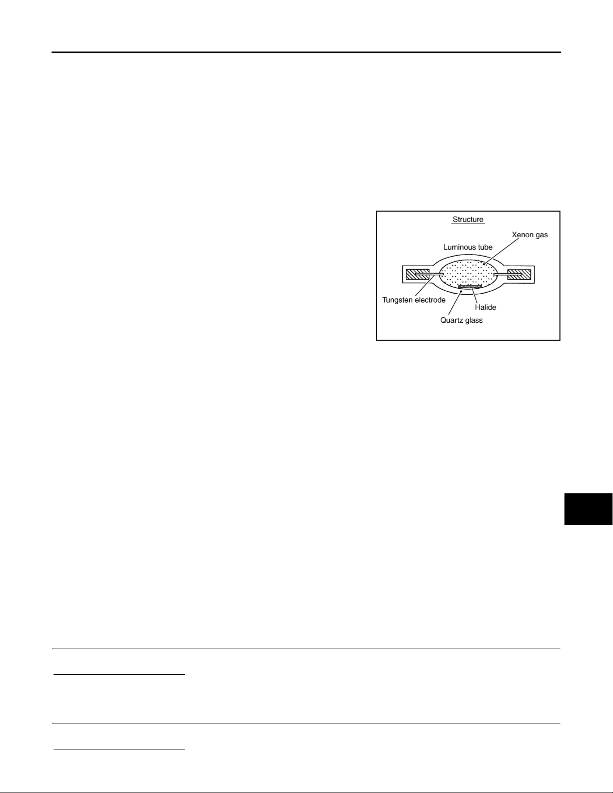
< COMPONENT DIAGNOSIS >
Revision: 2007 November 2008 EX35
XENON HEADLAMP
[XENON TYPE]
XENON HEADLAMP
Description INFOID:0000000003135335
OUTLINE
• The lamp light source is by the arch discharge by applying high voltage into the xenon gas-filled bulb instead
of the halogen bulb filament.
• Sight becomes more natural and brighter because the amount of light are gained adequately and the color of
light is sunshine-like white.
• The xenon bulb drops the amount of light, repeats blinking, and illuminates in red if the bulb reaches the service life.
ILLUMINATION PRINCIPLE
1. Discharging starts in high voltage pulse between bulb elec-
trodes.
2. Xenon gas is activated by current between electrodes. Pale light
is emitted.
3. The luminous tube (bulb) temperature elevates. Evaporated
halide is activated by discharge. The color of light changes into
white.
NOTE:
• Brightness and the color of light may change slightly immediately
after the headlamp turned ON until the xenon bulb becomes stable. This is not malfunction.
• Illumination time lag may occur between right and left. This is not
malfunction.
JPLIA0421GB
A
B
C
D
E
F
G
H
PRECAUTIONS FOR TROUBLE DIAGNOSIS
Representative malfunction examples are; "Light does not turn ON", "Light blinks", and "Brightness is inadequate." The cause often be the xenon bulb. Such malfunctions, however, are occurred occasionally by HID
control unit malfunction or lamp case malfunction. Specify the malfunctioning part with diagnosis procedure.
WARNING:
• Never touch the harness, HID control unit, the inside and metal part of lamp when turning the headlamp ON or operating the light switch.
• Never work with wet hands.
CAUTION:
• Never perform HID control unit circuit diagnosis with a circuit tester or an equivalent.
• Temporarily install the headlamp on the vehicle. Connect the battery to the connector (vehicle side)
when checking ON/OFF status.
• Disconnect the battery negative terminal before disconnecting the lamp socket connector or the harness connector.
• Check for fusing of the fusible link(s), open around connector, short, disconnection if the symptom
is caused by electric error.
NOTE:
• Turn the switch OFF once before turning ON, if the ON/OFF is inoperative.
• The xenon bulb drops the amount of light, repeats blinking, and illuminates in red if the bulb reaches the service life.
Diagnosis Procedure INFOID:0000000003135336
1.CHECK XENON BULB
Install the normal bulb to the applicable headlamp. Check that the xenon bulb is turned ON.
Is the headlamp turned ON?
YES >> Replace the xenon bulb.
NO >> GO TO 2.
2.CHECK HID CONTROL UNIT
I
J
K
EXL
M
N
O
P
Install the normal HID control unit to the applicable headlamp. Check that the lamp is turned ON.
Is the headlamp turned ON?
EXL-71
Page 72

XENON HEADLAMP
Revision: 2007 November 2008 EX35
< COMPONENT DIAGNOSIS >
YES >> Replace HID control unit.
NO >> GO TO 3.
[XENON TYPE]
3.CHECK XENON HEADLAMP HOUSING ASSEMBLY
Install the normal xenon headlamp housing assembly to the applicable headlamp. Check that the xenon headlamp is turned ON.
Is the headlamp turned ON?
YES >> Replace the front combination lamp. (Xenon headlamp housing voltage converter malfunctions.)
NO >> Xenon headlamp is normal. check the headlamp control system.
EXL-72
Page 73
< COMPONENT DIAGNOSIS >
Revision: 2007 November 2008 EX35
HEADLAMP LEVELIZER CIRCUIT
[XENON TYPE]
HEADLAMP LEVELIZER CIRCUIT
Description INFOID:0000000003135337
The headlamp levelizer adjusts the headlamp light axis upward and downward with the aiming motor integrated in the front combination lamp.
Component Function Check INFOID:0000000003135338
1.CHECK AIMING MOTOR OPERATION
CONSULT-III ACTIVE TEST
1. Start the engine.
2. Turn the lighting switch 2ND.
3. Select “LEVELIZER TEST” of ADAPTIVE LIGHT active test item.
4. With operating the test item, check the operation.
Test item
Light axis angle
LEVELIZER TEST
Origin 0° —
Peak 2.5° 450 mm (17.9 in)
(Reference value)
Is the operation normal?
YES >> Headlamp levelizer circuit is normal.
NO >> Refer to EXL-73, "Diagnosis Procedure"
10 m (32.8 ft)-forward
light axis change refer-
ence quantity
(Approx.)
.
A
B
C
D
E
F
G
H
Diagnosis Procedure INFOID:0000000003135339
1.CHECK AIMING MOTOR DRIVE SIGNAL OUTPUT
CONSULT-III ACTIVE TEST
1. St art the engine.
2. Turn the light switch 2ND.
3. Select “LEVELIZER TEST” of ADAPTIVE LIGHT active test item.
4. With operating the test item, check the voltage between the AFS control unit harness connector and the
ground.
Terminals
(+) (−)
AFS control unit
Connector Terminal
RH
M16
LH 40
19
Ground
Test item
Voltage
(Approx.)
LEVELIZER TEST
Origin 8.8 V
Peak 1.9 V
Origin 8.8 V
Peak 1.9 V
Is the measurement value normal?
YES >> GO TO 2.
NO >> GO TO 3.
2.CHECK AIMING MOTOR DRIVE SIGNAL CIRCUIT INPUT
I
J
K
EXL
M
N
O
P
1. Turn the ignition switch OFF.
2. Disconnect AFS control unit connector and aiming motor connector.
3. Check continuity between AFS control unit harness connector and the aiming motor harness connector.
EXL-73
Page 74
< COMPONENT DIAGNOSIS >
Revision: 2007 November 2008 EX35
HEADLAMP LEVELIZER CIRCUIT
[XENON TYPE]
AFS control unit Aiming motor
Connector Terminal Connector Terminal
RH
LH 40 E56 1
M16
19 E26 1
Continuity
Existed
Does continuity exist?
YES >> Replace the front combination lamp.
NO >> Repair the harnesses and connectors.
3.CHECK AIMING MOTOR DRIVE SIGNAL SHORT CIRCUIT
1. Turn the ignition switch OFF.
2. Disconnect AFS control unit connector and aiming motor connector.
3. Check continuity between AFS control unit harness connector and ground.
AFS control unit
Connector Terminal
RH
LH 40
M16
19
Ground
Does continuity exist?
YES >> Repair the harness and connectors.
NO >> Replace AFS control unit.
Continuity
Not existed
EXL-74
Page 75
< COMPONENT DIAGNOSIS >
Revision: 2007 November 2008 EX35
FRONT FOG LAMP CIRCUIT
[XENON TYPE]
FRONT FOG LAMP CIRCUIT
Component Function Check INFOID:0000000003135340
1.CHECK FRONT FOG LAMP OPERATION
IPDM E/R AUTO ACTIVE TEST
1. Activate IPDM E/R auto active test. Refer to PCS-11, "Diagnosis Description"
2. Check that the front fog lamp is turned ON.
CONSULT-III ACTIVE TEST
1. Select "EXTERNAL LAMPS" of IPDM E/R active test item.
2. With operating the test items, Check that the front fog lamp is turned ON.
Fog : Front fog lamp ON
Off : Front fog lamp OFF
Is the front fog lamp turned ON?
YES >> Front fog lamp circuit is normal.
NO >> Refer to EXL-75, "Diagnosis Procedure"
.
.
Diagnosis Procedure INFOID:0000000003135341
1.CHECK FRONT FOG LAMP FUSE
1. Turn the ignition switch OFF.
2. Check that the following fuses are not fusing.
A
B
C
D
E
F
G
H
Unit Location Fuse No. Capacity
Front fog lamp IPDM E/R #58 15 A
Is the fuse fusing?
YES >> GO TO 2.
NO >> GO TO 3.
2.CHECK FRONT FOG LAMP SHORT CIRCUIT
1. Disconnect IPDM E/R connector and the front fog lamp connector.
2. Check continuity between the IPDM E/R harness connector and the ground.
IPDM E/R
Connector Terminal
RH
LH 87
Does continuity exist?
YES >> Repair the harnesses or connectors. And then replace the fuse.
NO >> Replace the fuse. (Replace IPDM E/R if the fuse is fusing again.)
E8
86
Ground
Continuity
Not existed
3.CHECK FRONT FOG LAMP BULB
Check the applicable lamp bulb.
Is the bulb normal?
YES >> GO TO 4.
NO >> Replace the bulb.
4.CHECK FRONT FOG LAMP OUTPUT VOLTAGE
I
J
K
EXL
M
N
O
P
CONSULT-III ACTIVE TEST
1. Disconnect the front fog lamp connector.
2. Turn the ignition switch ON.
3. Select "EXTERNAL LAMPS" of IPDM E/R active test item.
EXL-75
Page 76
FRONT FOG LAMP CIRCUIT
Revision: 2007 November 2008 EX35
< COMPONENT DIAGNOSIS >
4. With operating the test items, check the voltage between the IPDM E/R harness connector and the
ground.
[XENON TYPE]
Terminals
(+) (−)
IPDM E/R
Connector Terminal
RH
E8
LH
86
87
Ground
Test item
EXTERNAL
LAMP
Fog
Off 0 V
Fog
Off 0 V
Voltage
(Approx.)
Battery
voltage
Battery
voltage
Is the measurement value normal?
YES >> GO TO 5.
NO >> Replace IPDM E/R.
5.CHECK FRONT FOG LAMP OPEN CIRCUIT
1. Turn the ignition switch OFF.
2. Disconnect IPDM E/R connector.
3. Check continuity between the IPDM E/R harness connector and the front fog lamp harness connector.
IPDM E/R Front fog lamp
Connector Terminal Connector Terminal
RH
LH 87 E64 1
E8
86 E34 1
Continuity
Existed
Does continuity exist?
YES >> GO TO 6.
NO >> Repair the harnesses or connectors.
6.CHECK FRONT FOG LAMP GROUND CIRCUIT OPEN CIRCUIT
Check continuity between the front fog lamp harness connector and the ground.
Front fog lamp
Connector Terminal
RH E34 2
LH E64 2
Ground
Continuity
Existed
Does continuity exist?
YES >> Replace the front fog lamp.
NO >> Repair the harnesses or connectors.
EXL-76
Page 77
< COMPONENT DIAGNOSIS >
Revision: 2007 November 2008 EX35
PARKING LAMP CIRCUIT
[XENON TYPE]
PARKING LAMP CIRCUIT
Component Function Check INFOID:0000000003135342
1.CHECK PARKING LAMP OPERATION
IPDM E/R AUTO ACTIVE TEST
1. Activate IPDM E/R auto active test. Refer to PCS-11, "Diagnosis Description"
2. Check that the parking lamp is turned ON.
CONSULT-III ACTIVE TEST
1. Select "EXTERNAL LAMPS" of IPDM E/R active test item.
2. With operating the test items, check that the parking lamp is turned ON.
TAIL : Parking lamp ON
Off : Parking lamp OFF
Is the parking lamp turned ON?
YES >> Parking lamp circuit is normal.
NO >> Refer to EXL-77, "Diagnosis Procedure"
.
.
Diagnosis Procedure INFOID:0000000003135343
1.CHECK PARKING LAMP FUSE
1. Turn the ignition switch OFF.
2. Check that the following fuses are not fusing.
A
B
C
D
E
F
G
H
Unit Location Fuse No. Capacity
Parking lamp IPDM E/R #52 10 A
Is the fuse fusing?
YES >> GO TO 2.
NO >> GO TO 3.
2.CHECK PARKING LAMP SHORT CIRCUIT
1. Disconnect IPDM E/R connector and the front combination lamp connector.
2. Check continuity between the IPDM E/R harness connector and the ground.
IPDM E/R
Connector Terminal
RH
LH 92
Does continuity exist?
YES >> Repair the harnesses or connectors. And then replace the fuse.
NO >> Replace the fuse. (Replace IPDM E/R if fusing is found again.)
E9
91
Ground
Continuity
Not existed
3.CHECK PARKING LAMP BULB
Check the applicable lamp bulb.
Is the bulb normal?
YES >> GO TO 4.
NO >> Replace the bulb.
4.CHECK PARKING LAMP OUTPUT VOLTAGE
I
J
K
EXL
M
N
O
P
CONSULT-III ACTIVE TEST
1. Disconnect the front combination lamp connector.
2. Turn the ignition switch ON.
3. Select "EXTERNAL LAMPS" of IPDM E/R active test item.
EXL-77
Page 78
PARKING LAMP CIRCUIT
Revision: 2007 November 2008 EX35
< COMPONENT DIAGNOSIS >
4. With operating the test items, check the voltage between the IPDM E/R harness connector and the
ground.
[XENON TYPE]
Terminals
(+) (−)
IPDM E/R
Connector Terminal
RH
E9
LH 92
91
Ground
Test item
EXTERNAL
LAMP
TAIL
Off 0 V
TAIL
Off 0 V
Voltage
(Approx.)
Battery
voltage
Battery
voltage
Is the measurement value normal?
YES >> GO TO 5.
NO >> Replace IPDM E/R.
5.CHECK PARKING LAMP OPEN CIRCUIT
1. Turn the ignition switch OFF.
2. Disconnect IPDM E/R connector.
3. Check continuity between the IPDM E/R harness connector and the front combination lamp harness connector.
IPDM E/R Front combination lamp
Connector Terminal Connector Terminal
RH
LH 92 E58 8
E9
91 E28 8
Continuity
Existed
Does continuity exist?
YES >> GO TO 6.
NO >> Repair the harnesses or connectors.
6.CHECK PARKING LAMP GROUND OPEN CIRCUIT
Check continuity between the front combination lamp harness connector and the ground.
Front combination lamp
Connector Terminal
RH E28 4
LH E58 4
Ground
Continuity
Existed
Does continuity exist?
YES >> Replace the front combination lamp.
NO >> Repair the harnesses or connectors.
EXL-78
Page 79
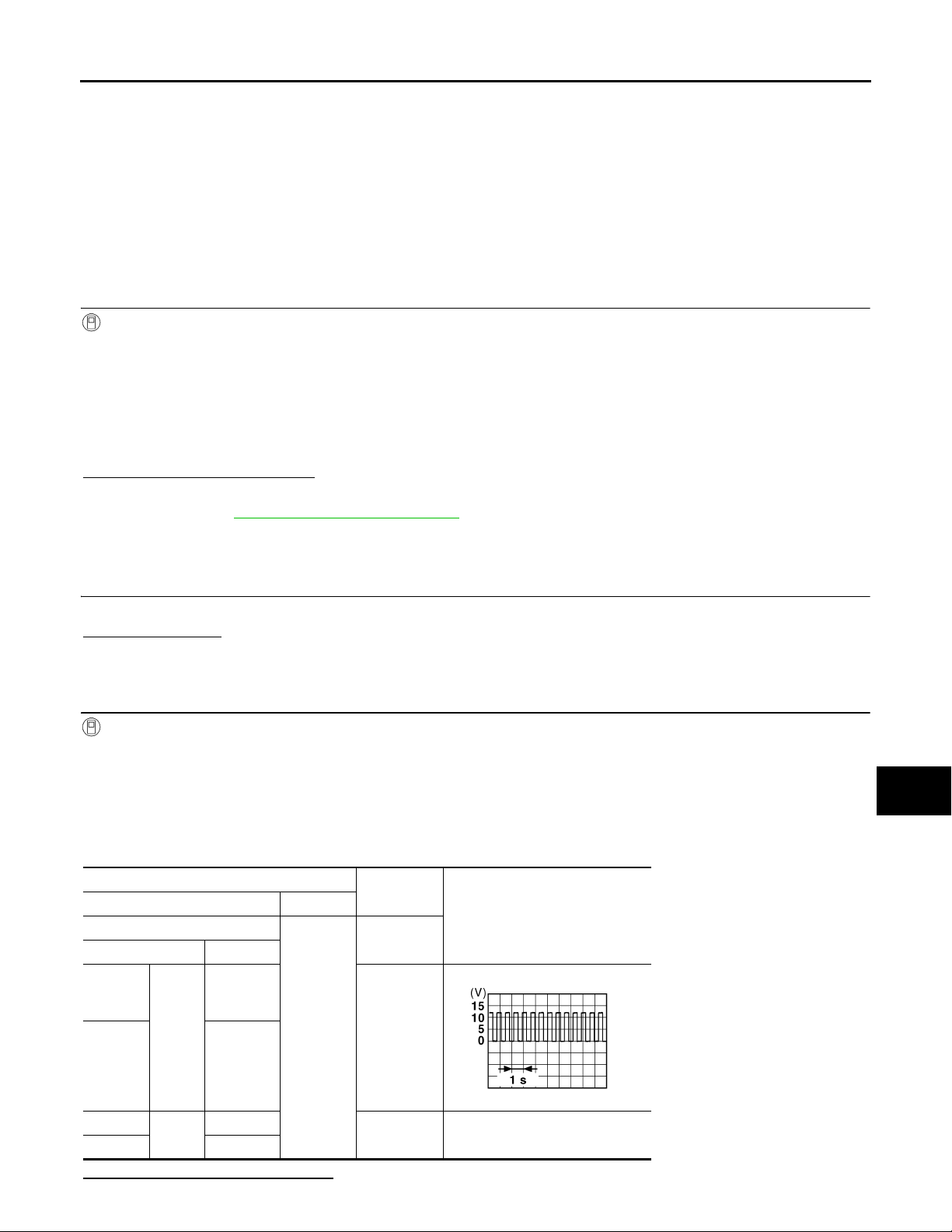
< COMPONENT DIAGNOSIS >
Revision: 2007 November 2008 EX35
TURN SIGNAL LAMP CIRCUIT
[XENON TYPE]
TURN SIGNAL LAMP CIRCUIT
Description INFOID:0000000003135344
BCM performs the high flasher operation (fail-safe) if any bulb or harness of the turn signal lamp circuit is
open.
NOTE:
Turn signal lamp blinks at normal speed when using the hazard warning lamp.
Component Function Check INFOID:0000000003135345
1.CHECK TURN SIGNAL LAMP
CONSULT-III ACTIVE TEST
1. Select "FLASHER" of BCM (FLASHER) active test item.
2. With operating the test items, check that the turn signal lamp blinks.
LH : Turn signal lamp LH blinking
RH : Turn signal lamp RH blinking
Off : The turn signal lamp OFF
Does the turn signal lamp blink?
YES >> Turn signal lamp circuit is normal.
NO >> Refer to EXL-79, "Diagnosis Procedure"
Diagnosis Procedure INFOID:0000000003135346
.
A
B
C
D
E
F
G
H
1.CHECK TURN SIGNAL LAMP BULB
Check the applicable lamp bulb.
Is the bulb normal?
YES >> GO TO 2.
NO >> Replace the bulb.
2.CHECK TURN SIGNAL LAMP OUTPUT VOLTAGE
CONSULT-III ACTIVE TEST
1. Turn the ignition switch OFF.
2. Disconnect the front combination lamp connector or the rear combination lamp connector.
3. Turn the ignition switch ON.
4. Select "FLASHER" of BCM (FLASHER) active test item.
5. With operating the turn signal switch, check the voltage between the BCM harness connector and the
ground.
Terminals
(+) (−)
BCM
Connector Terminal
Front RH
17
Test item
Voltage (Approx.)
FLASHER
I
J
K
EXL
M
N
O
M119
Front LH 18
Rear RH
Rear LH 25
M120
20
Ground
LH or RH
PKID0926E
Off 0 V
Is the measurement value normal?
EXL-79
P
Page 80
TURN SIGNAL LAMP CIRCUIT
Revision: 2007 November 2008 EX35
< COMPONENT DIAGNOSIS >
YES >> GO TO 3.
NO >> Replace BCM.
[XENON TYPE]
3.CHECK TURN SIGNAL LAMP OPEN CIRCUIT
1. Turn the ignition switch OFF.
2. Disconnect BCM connector.
3. Check the continuity between the BCM harness connector and the front combination lamp or the rear
combination lamp harness connector.
BCM
Connector Terminal Connector Terminal
Front RH
Front LH 18 E58 6
Rear RH
Rear LH 25 B260 1
M119
M120
17 E28 6
20 B261 1
Front combination lamp/
Rear combination lamp
Continuity
Existed
Does continuity exist?
YES >> GO TO 4.
NO >> Repair the harnesses or connectors.
4.CHECK TURN SIGNAL LAMP SHORT CIRCUIT
Check continuity between the BCM harness connector and the ground.
BCM
Connector Terminal
Front RH
Front LH 18
Rear RH
Rear LH 25
M119
M120
17
20
Ground
Continuity
Not existed
Does continuity exist?
YES >> Repair the harnesses or connectors.
NO >> GO TO 5.
5.CHECK TURN SIGNAL LAMP GROUND OPEN CIRCUIT
Check the continuity between the BCM harness connector and the front combination lamp or the rear combination lamp and the ground.
Front combination lamp /
Rear combination lamp
Connector Terminal
Front RH E28 4
Front LH E58 4
Rear RH B261 2
Rear LH B260 2
Ground
Continuity
Existed
Does continuity exist?
YES >> Replace the front combination lamp or the rear combination lamp.
NO >> Repair the harnesses or connectors.
EXL-80
Page 81
< COMPONENT DIAGNOSIS >
Revision: 2007 November 2008 EX35
OPTICAL SENSOR
[XENON TYPE]
OPTICAL SENSOR
Description INFOID:0000000003135347
Optical sensor converts the outside brightness (lux) to voltage and transmits the optical sensor signal to BCM.
Component Function Check INFOID:0000000003135348
1.CHECK OPTICAL SENSOR SIGNAL BY CONSULT-III
CONSULT-III DATA MONITOR
1. Turn the ignition switch ON.
2. Select "OPTICAL SENSOR" of BCM (HEADLAMP) data monitor item.
3. Turn the lighting switch AUTO.
4. With the optical sensor illuminating, check the monitor status.
Monitor item Condition Voltage (Approx.)
When illuminat-
OPTICAL SENSOR
*: Illuminates the optical sensor. The value may be less t han the standard value if brightness is weak.
Optical sensor
ing
When shutting
off light
Is the item status normal?
YES >> Optical sensor is normal.
NO >> Refer to EXL-81, "Diagnosis Procedure"
3.1 V or more *
0.6 V or less
.
A
B
C
D
E
F
G
H
Diagnosis Procedure INFOID:0000000003135349
1.CHECK OPTICAL SENSOR POWER SUPPLY INPUT
1. Turn the ignition switch ON.
2. Turn the lighting switch AUTO.
3. Check the voltage between the optical sensor harness connector and the ground.
Terminals
(+) (−)
Optical sensor
GroundConnector Terminal
M94 1 5 V
Voltage
(Approx.)
Is the measurement value normal?
YES >> GO TO 2.
NO >> GO TO 4.
2.CHECK OPTICAL SENSOR GROUND INPUT
Check the voltage between the optical sensor harness connector and the ground.
Terminals
(+) (−)
Optical sensor
GroundConnector Terminal
M94 3 0 V
Is the measurement value normal?
YES >> GO TO 3.
NO >> GO TO 6.
Voltage
(Approx.)
I
J
K
EXL
M
N
O
P
EXL-81
Page 82
OPTICAL SENSOR
Revision: 2007 November 2008 EX35
< COMPONENT DIAGNOSIS >
[XENON TYPE]
3.CHECK OPTICAL SENSOR SIGNAL OUTPUT
With illuminating the optical sensor, check the voltage between the optical sensor harness connector and the
ground.
Terminals
(+) (−)
Optical sensor
Connector Terminal
Ground
M94 2
*: Illuminate the optical sensor. The value may be less than t he standard if brightness is weak.
Condition
Optical sen-
sor
When illuminating
When shutting off light
Voltage
(Approx.)
3.1 V or
more *
0.6 V or less
Is the measurement value normal?
YES >> GO TO 7.
NO >> Replace the optical sensor.
4.CHECK OPTICAL SENSOR OPEN CIRCUIT
1. Turn the ignition switch OFF.
2. Disconnect the optical sensor connector and BCM connector.
3. Check continuity between the optical sensor harness connector and the BCM harness connector.
Optical sensor BCM
Connector Terminal Connector Terminal
M94 1 M123 138 Existed
Continuity
Does continuity exist?
YES >> GO TO 5.
NO >> Repair the harnesses or connectors.
5.CHECK OPTICAL SENSOR SHORT CIRCUIT
Check the continuity between the optical sensor harness connector and the ground.
Optical sensor
Connector Terminal
M94 1 Not existed
Ground
Continuity
Does continuity exist?
YES >> Repair the harnesses or connectors.
NO >> Replace BCM.
6.CHECK OPTICAL SENSOR GROUND OPEN CIRCUIT
1. Turn the ignition switch OFF.
2. Disconnect the optical sensor connector and BCM connector.
3. Check continuity between the optical sensor harness connector and the BCM harness connector.
Optical sensor BCM
Connector Terminal Connector Terminal
M94 3 M123 137 Existed
Continuity
Does continuity exist?
YES >> Replace BCM.
NO >> Repair the harnesses or connectors.
7.CHECK OPTICAL SENSOR SIGNAL OPEN CIRCUIT
EXL-82
Page 83
OPTICAL SENSOR
Revision: 2007 November 2008 EX35
< COMPONENT DIAGNOSIS >
1. Turn the ignition switch OFF.
2. Disconnect the optical sensor connector and BCM connector.
3. Check continuity between the optical sensor harness connector and the BCM harness connector.
[XENON TYPE]
A
Optical sensor BCM
Connector Terminal Connector Terminal
M94 2 M123 113 Existed
Continuity
Does continuity exist?
YES >> GO TO 8.
NO >> Repair the harnesses or connectors.
8.CHECK OPTICAL SENSOR SHORT CIRCUIT
Check the continuity between the optical sensor harness connector and the ground.
Optical sensor
Connector Terminal
M94 2 Not existed
Ground
Does continuity exist?
YES >> Repair the harnesses or connectors.
NO >> Replace BCM.
Continuity
B
C
D
E
F
G
H
I
J
K
EXL
M
N
O
P
EXL-83
Page 84
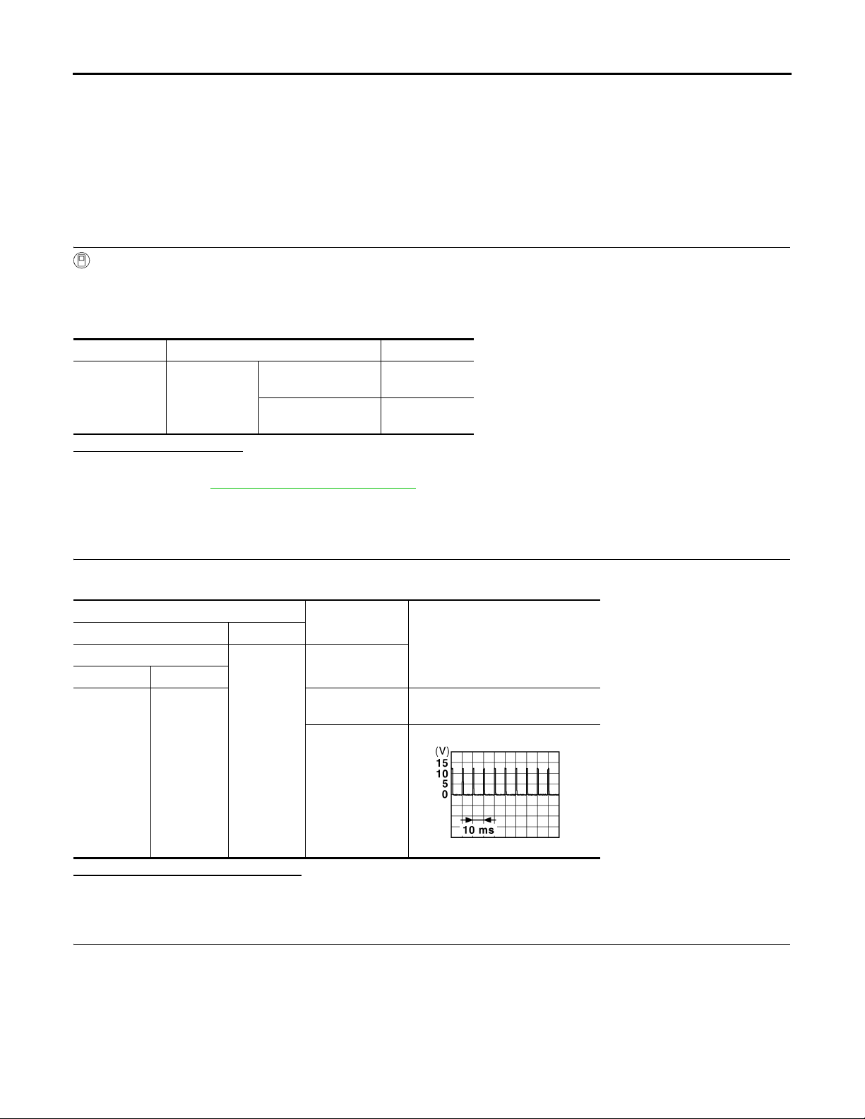
HAZARD SWITCH
B
Revision: 2007 November 2008 EX35
< COMPONENT DIAGNOSIS >
[XENON TYPE]
HAZARD SWITCH
Description INFOID:0000000003135350
Hazard switch is integrated in the multifunction switch. Hazard switch inputs the signals to BCM when pressing the switch.
Component Function Check INFOID:0000000003135351
1.CHECK HAZARD SWITCH SIGNAL BY CONSULT-III
CONSULT-III DAT A MONITOR
1. Turn the ignition switch ON.
2. Select "HAZARD SW" of BCM (FLASHER) data monitor item.
3. With operating the hazard switch, check the monitor status.
Monitor item Condition Monitor status
While pressing the
HAZARD SW Hazard switch
switch
While not pressing
the switch
Is the item status normal?
YES >> Hazard switch circuit is normal.
NO >> Refer to EXL-84, "Diagnosis Procedure"
On
Off
.
Diagnosis Procedure INFOID:0000000003135352
1.CHECK HAZARD SWITCH SIGNAL INPUT
With operating the hazard switch, check the voltage between the BCM harness connector and the ground.
Terminals
(+) (−)
BCM
Connector Terminal
Ground
M122 110
Condition
Hazard switch
While pressing
the switch
While not pressing the switch
Voltage (Approx.)
0 V
JPMIA0012G
Is the measurement value normal?
YES >> Replace BCM.
NO >> GO TO 2.
2.CHECK HAZARD SWITCH SIGNAL OPEN CIRCUIT
1. Turn the ignition switch OFF.
2. Disconnect the multifunction switch connector and BCM connector.
3. Check continuity between the multifunction switch harness connector and the BCM harness connector.
EXL-84
Page 85
< COMPONENT DIAGNOSIS >
Revision: 2007 November 2008 EX35
HAZARD SWITCH
[XENON TYPE]
Multifunction switch BCM
Connector Terminal Connector Terminal
M72 16 M122 110 Existed
Continuity
Does continuity exist?
YES >> GO TO 3.
NO >> Repair the harnesses or connectors.
3.CHECK HAZARD SWITCH SIGNAL SHORT CIRCUIT
Check continuity between the multifunction switch harness connector and the ground.
Multifunction switch
Connector Terminal
M72 16 Not existed
Ground
Continuity
Does continuity exist?
YES >> Repair the harnesses or connectors.
NO >> GO TO 4.
4.CHECK HAZARD SWITCH GROUND OPEN CIRCUIT
Check continuity between the multifunction switch harness connector and the ground.
Multifunction switch
Connector Terminal
M72 1 Existed
Ground
Does continuity exist?
YES >> Replace the hazard switch (multifunction switch).
NO >> Repair the harnesses or connectors.
Continuity
A
B
C
D
E
F
G
H
I
J
K
EXL
M
N
O
P
EXL-85
Page 86
TAIL LAMP CIRCUIT
Revision: 2007 November 2008 EX35
< COMPONENT DIAGNOSIS >
[XENON TYPE]
TAIL LAMP CIRCUIT
Component Function Check INFOID:0000000003135353
1.CHECK TAIL LAMP OPERATION
IPDM E/R AUTO ACTIVE TEST
1. Activate IPDM E/R auto active test. Refer to PCS-11, "Diagnosis Description"
2. Check that the tail lamp is turned ON.
CONSULT-III ACTIVE TEST
1. Select "EXTERNAL LAMPS" of IPDM E/R active test item.
2. With operating the test items, check that the tail lamp is turned ON.
TAIL : Tail lamp ON
Off : Tail lamp OFF
Is the tail lamp turned ON?
YES >> Tail lamp circuit is normal.
NO >> Refer to EXL-86, "Diagnosis Procedure"
.
.
Diagnosis Procedure INFOID:0000000003135354
1.CHECK TAIL LAMP FUSE
1. Turn the ignition switch OFF.
2. Check that the following fuses are not fusing.
Unit Location Fuse No. Capacity
•Tail lamp
• Rear side marker lamp
• License plate lamp
Is the fuse fusing?
YES >> Repair the malfunctioning part before replacing the fuse.
NO >> GO TO 2.
IPDM E/R #53 10 A
2.CHECK TAIL LAMP OUTPUT VOLTAGE
CONSULT-III ACTIVE TEST
1. Disconnect the rear combination lamp connector.
2. Turn the ignition switch ON.
3. Select "EXTERNAL LAMPS" of IPDM E/R active test item.
4. With operating the test items, check the voltage between the IPDM E/R harness connector and the
ground.
Terminals
(+) (−)
IPDM E/R
Connector Terminal
Ground
E5 7
Is the measurement value normal?
YES >> GO TO 3.
NO >> Replace IPDM E/R.
Test item
EXTERNAL
LAMP
TAIL
Off 0 V
Voltage
(Approx.)
Battery volt-
age
3.CHECK TAIL LAMP OPEN CIRCUIT
1. Turn the ignition switch OFF.
2. Disconnect IPDM E/R connector.
EXL-86
Page 87
TAIL LAMP CIRCUIT
Revision: 2007 November 2008 EX35
< COMPONENT DIAGNOSIS >
3. Check continuity between the IPDM E/R harness connector and the rear combination lamp harness connector.
[XENON TYPE]
A
IPDM E/R Rear combination lamp
Connector Terminal Connector Terminal
RH
LH B60 1
E5 7
B232 1
Continuity
Existed
Does continuity exist?
YES >> GO TO 4.
NO >> Repair the harnesses or connectors.
4.CHECK TAIL LAMP GROUND OPEN CIRCUIT
Check continuity between the rear combination lamp harness connector and the ground.
Rear combination lamp
Connector Terminal
RH B232 4
LH B60 4
Ground
Does continuity exist?
YES >> Replace the rear combination lamp.
NO >> Repair the harnesses or connectors.
Continuity
Existed
B
C
D
E
F
G
H
I
J
K
EXL
M
N
O
P
EXL-87
Page 88
LICENSE PLATE LAMP CIRCUIT
Revision: 2007 November 2008 EX35
< COMPONENT DIAGNOSIS >
[XENON TYPE]
LICENSE PLATE LAMP CIRCUIT
Component Function Check INFOID:0000000003135355
NOTE:
Check the tail lamp circuit if the tail lamp and the license plate lamp are not turned ON.
1.CHECK LICENSE PLATE LAMP OPERATION
IPDM E/R AUTO ACTIVE TEST
1. Activate IPDM E/R auto active test. Refer to PCS-11, "Diagnosis Description"
2. Check that the license plate lamp is turned ON.
CONSULT-III ACTIVE TEST
1. Select "EXTERNAL LAMPS" of IPDM E/R active test item.
2. With operating the lighting switch, check that the license plate lamp is turned ON.
TAIL : License plate lamp ON
Off : License plate lamp OFF
Is the license plate lamp turned ON?
YES >> License plate lamp circuit is normal.
NO >> Refer to EXL-88, "Diagnosis Procedure"
.
Diagnosis Procedure INFOID:0000000003135356
.
1.CHECK LICENSE PLATE LAMP BULB
Check the applicable lamp bulb.
Is the bulb normal?
YES >> GO TO 2.
NO >> Replace the bulb.
2.CHECK LICENSE PLATE LAMP OPEN CIRCUIT
1. Turn the ignition switch OFF.
2. Disconnect IPDM E/R connector and the license plate lamp connector.
3. Check continuity between the IPDM E/R harness connector and the license plate lamp harness connec-
tor.
IPDM E/R License plate lamp
Connector Terminal Connector Terminal
RH
LH D112 1
Does continuity exist?
YES >> GO TO 3.
NO >> Repair the harnesses or connectors.
E5 7
D117 1
Continuity
Existed
3.CHECK LICENSE PLATE LAMP GROUND OPEN CIRCUIT
Check continuity between the license plate lamp harness connector and the ground.
License plate lamp
Connector Terminal
RH D117 2
LH D112 2
Does continuity exist?
YES >> Replace the license plate lamp.
NO >> Repair the harnesses or connectors.
Ground
Continuity
Existed
EXL-88
Page 89
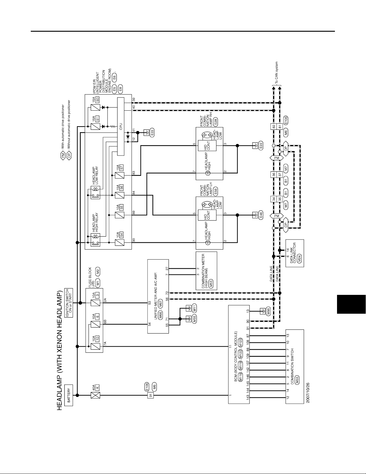
< COMPONENT DIAGNOSIS >
B
Revision: 2007 November 2008 EX35
HEADLAMP SYSTEM
[XENON TYPE]
HEADLAMP SYSTEM
Wiring Diagram - HEADLAMP - INFOID:0000000003135357
A
B
C
D
E
F
G
H
JCLWM1232G
I
J
K
EXL
M
N
O
P
EXL-89
Page 90
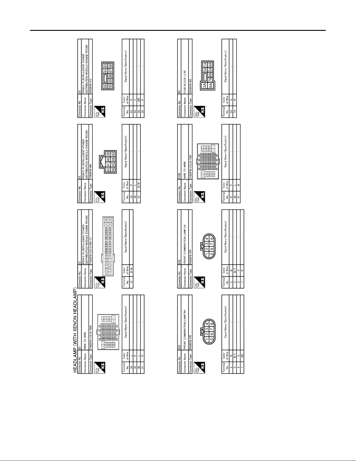
< COMPONENT DIAGNOSIS >
B
Revision: 2007 November 2008 EX35
HEADLAMP SYSTEM
[XENON TYPE]
JCLWM1233G
EXL-90
Page 91
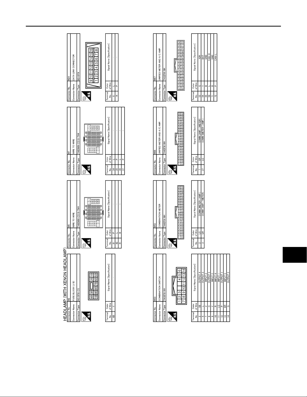
< COMPONENT DIAGNOSIS >
B
Revision: 2007 November 2008 EX35
HEADLAMP SYSTEM
[XENON TYPE]
A
B
C
D
E
F
G
H
I
J
K
EXL
M
N
O
JCLWM1234G
EXL-91
P
Page 92
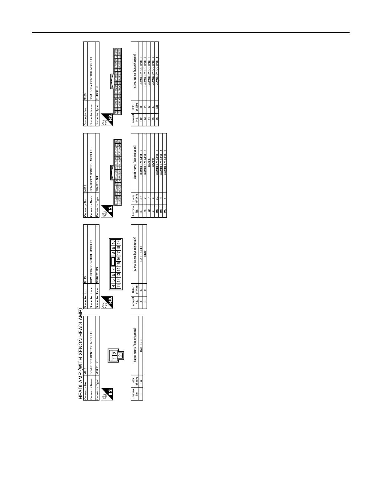
< COMPONENT DIAGNOSIS >
B
Revision: 2007 November 2008 EX35
HEADLAMP SYSTEM
[XENON TYPE]
JCLWM1235G
EXL-92
Page 93
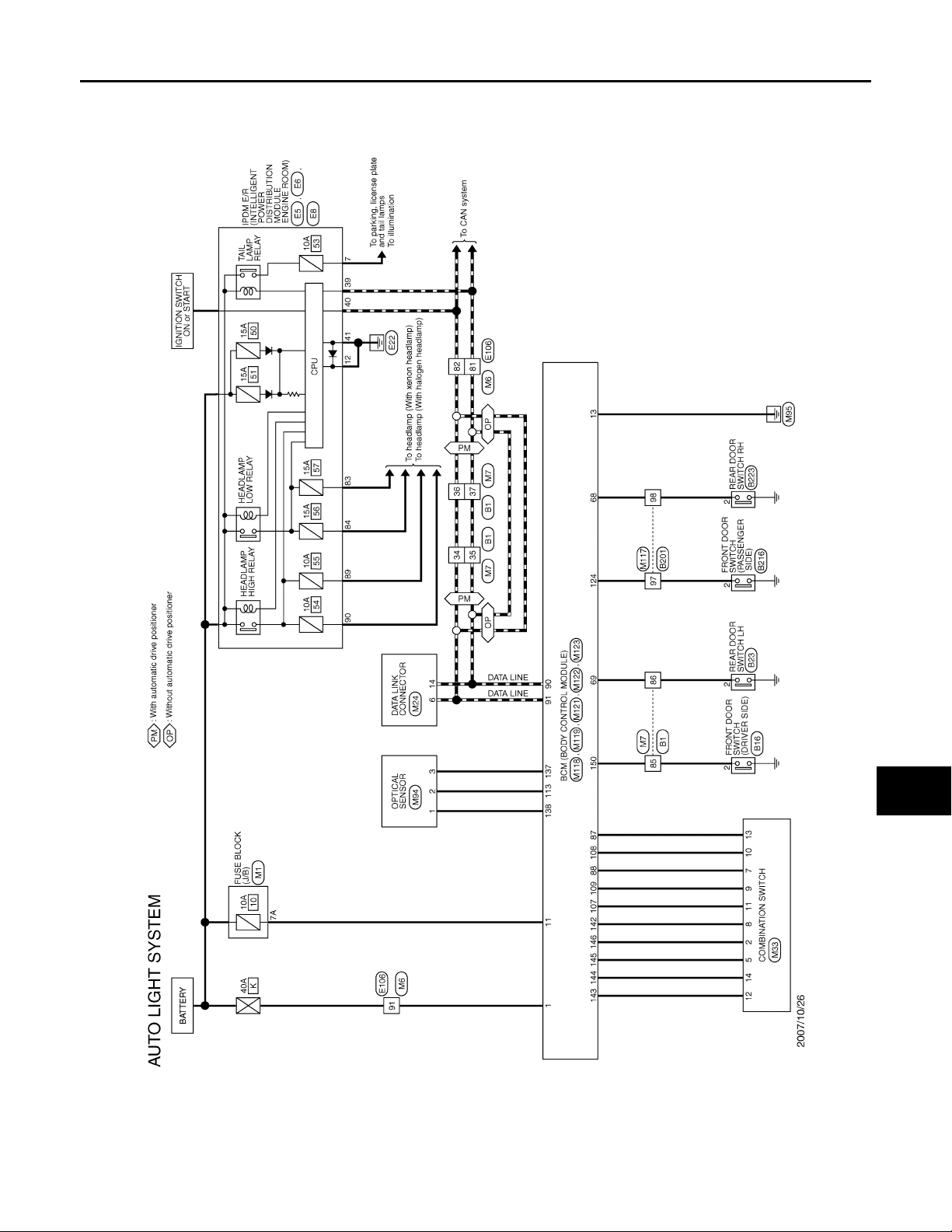
< COMPONENT DIAGNOSIS >
B
Revision: 2007 November 2008 EX35
AUTO LIGHT SYSTEM
[XENON TYPE]
AUTO LIGHT SYSTEM
Wiring Diagram - AUTO LIGHT SYSTEM - INFOID:0000000003135358
A
B
C
D
E
F
G
H
JCLWM1244G
I
J
K
EXL
M
N
O
P
EXL-93
Page 94
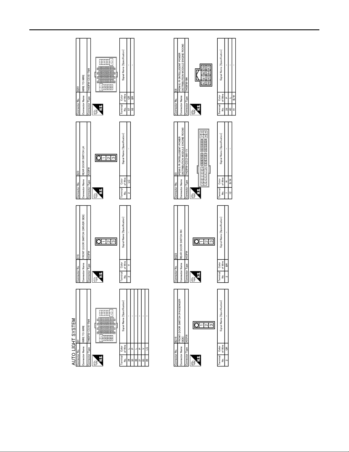
< COMPONENT DIAGNOSIS >
B
Revision: 2007 November 2008 EX35
AUTO LIGHT SYSTEM
[XENON TYPE]
JCLWM1245G
EXL-94
Page 95
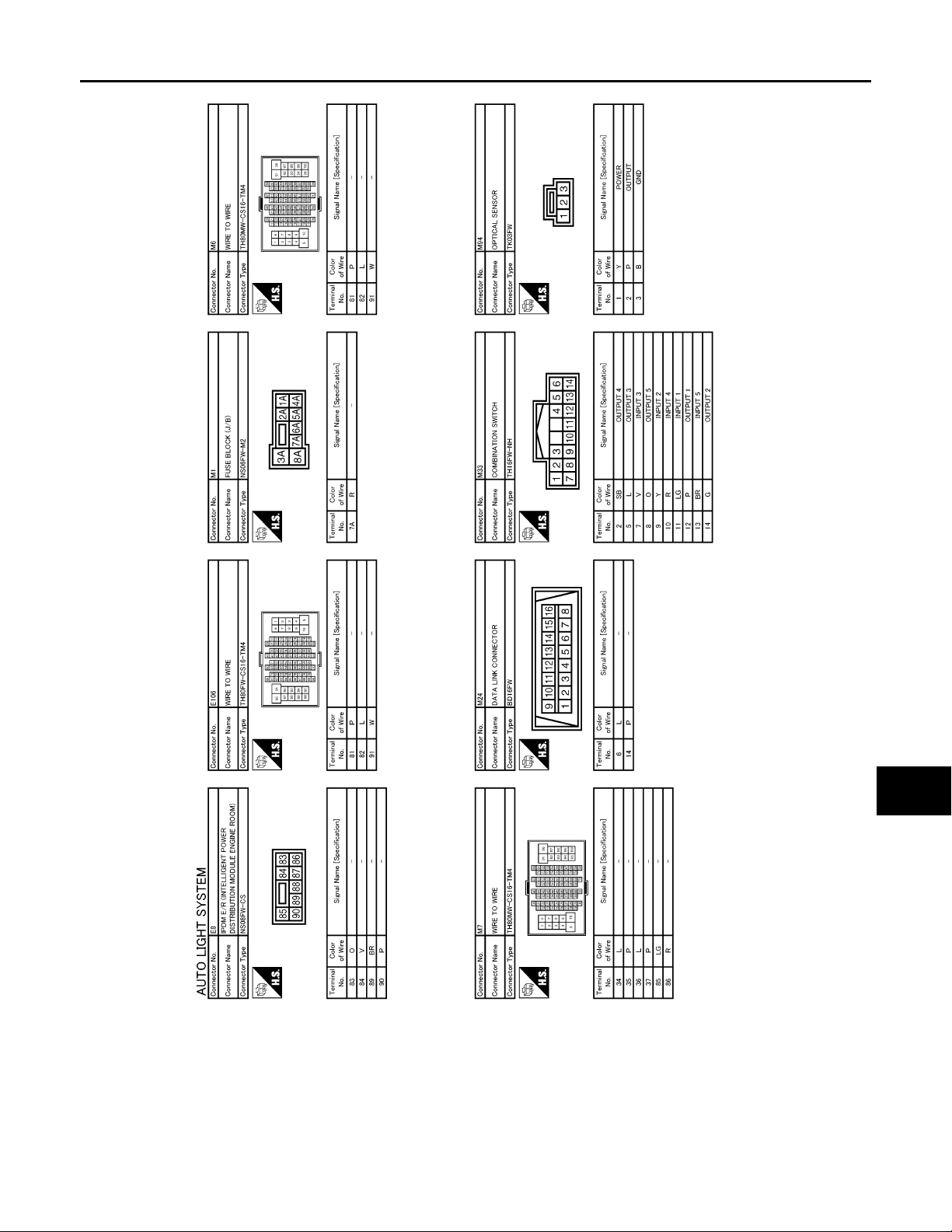
< COMPONENT DIAGNOSIS >
B
Revision: 2007 November 2008 EX35
AUTO LIGHT SYSTEM
[XENON TYPE]
A
B
C
D
E
F
G
H
I
J
K
EXL
M
N
O
JCLWM1246G
EXL-95
P
Page 96
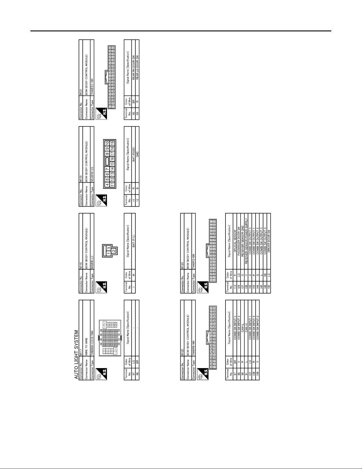
< COMPONENT DIAGNOSIS >
B
Revision: 2007 November 2008 EX35
AUTO LIGHT SYSTEM
[XENON TYPE]
JCLWM1247G
EXL-96
Page 97
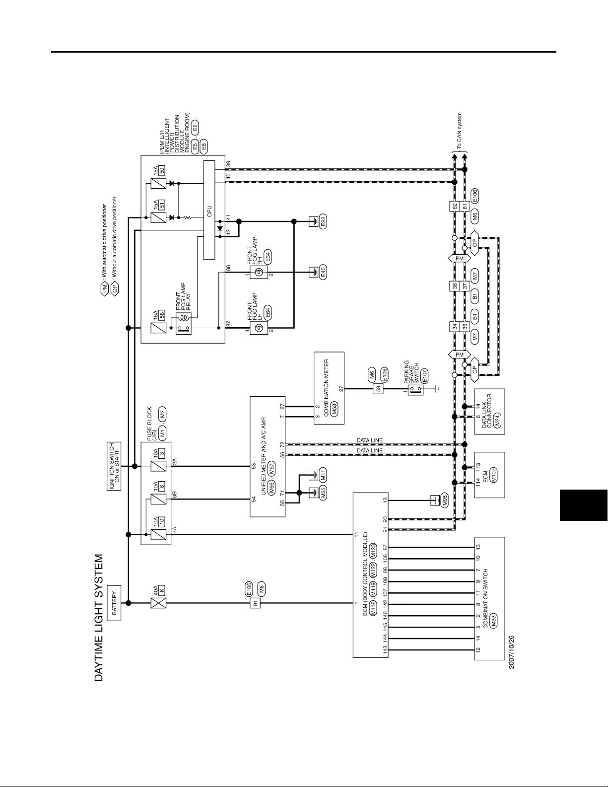
DAYTIME RUNNING LIGHT SYSTEM
B
Revision: 2007 November 2008 EX35
< COMPONENT DIAGNOSIS >
[XENON TYPE]
DAYTIME RUNNING LIGHT SYSTEM
Wiring Diagram - DAYTIME LIGHT SYSTEM - INFOID:0000000003135359
A
B
C
D
E
F
G
H
JCLWM1240G
I
J
K
EXL
M
N
O
P
EXL-97
Page 98
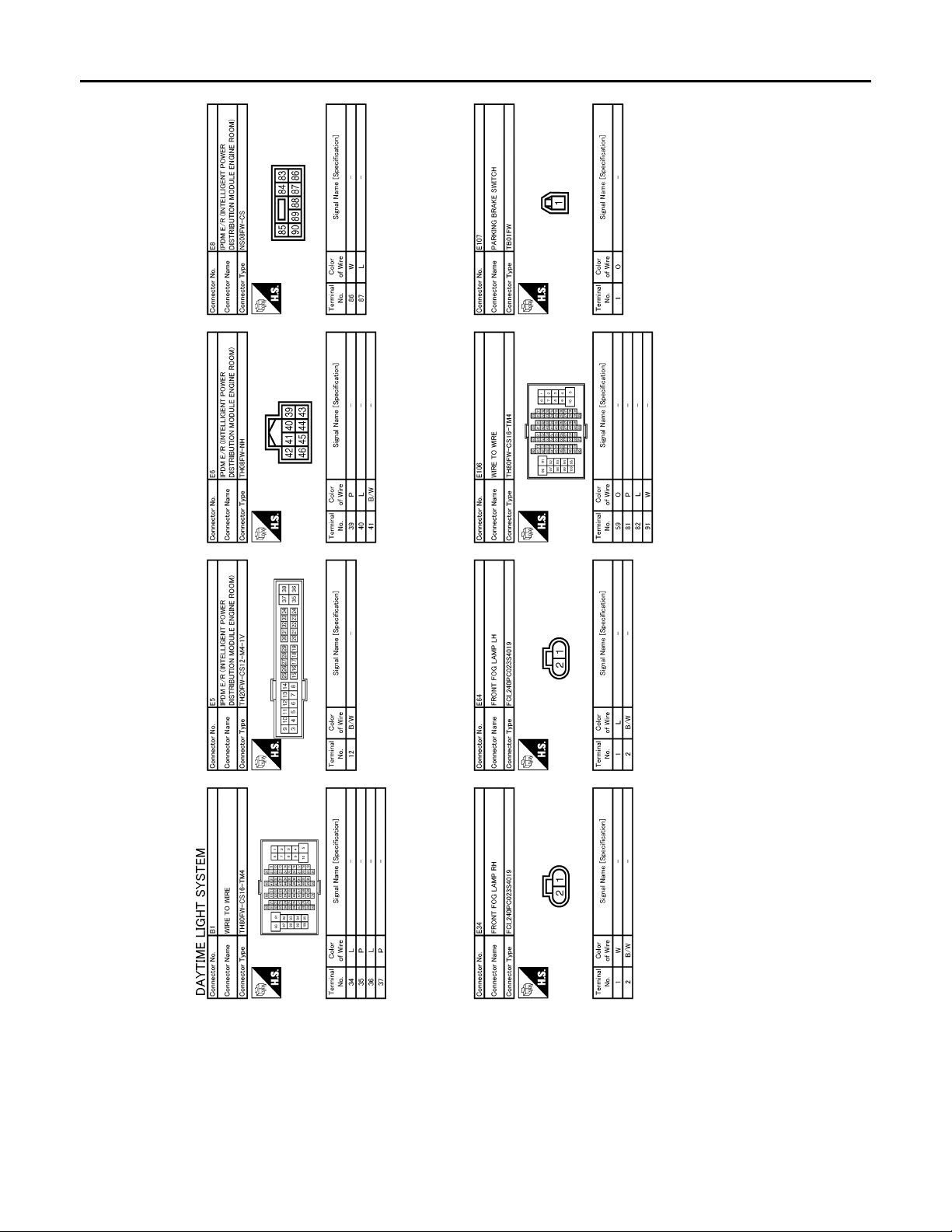
DAYTIME RUNNING LIGHT SYSTEM
B
Revision: 2007 November 2008 EX35
< COMPONENT DIAGNOSIS >
[XENON TYPE]
JCLWM1241G
EXL-98
Page 99
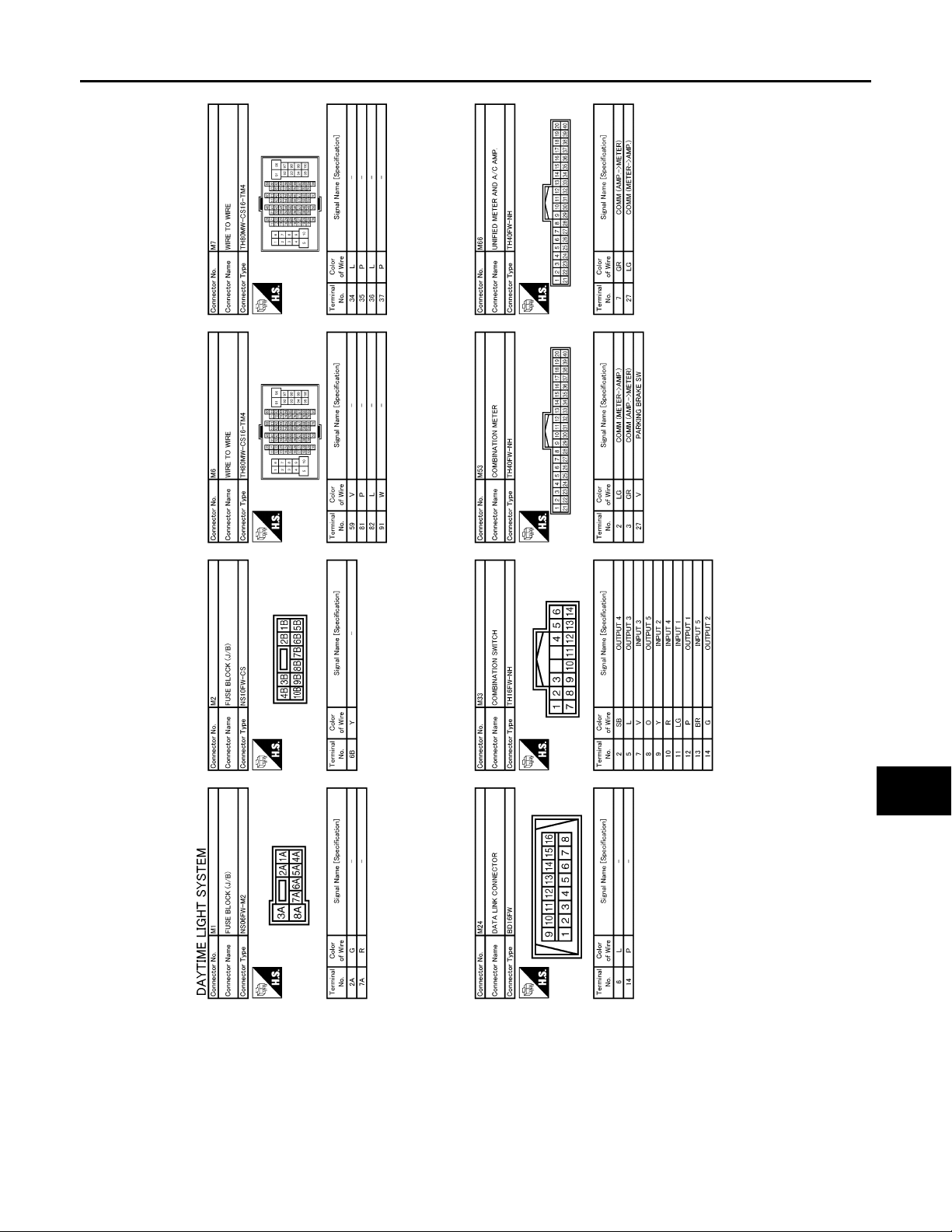
DAYTIME RUNNING LIGHT SYSTEM
B
Revision: 2007 November 2008 EX35
< COMPONENT DIAGNOSIS >
[XENON TYPE]
A
B
C
D
E
F
G
H
I
J
K
EXL
M
N
O
JCLWM1242G
EXL-99
P
Page 100
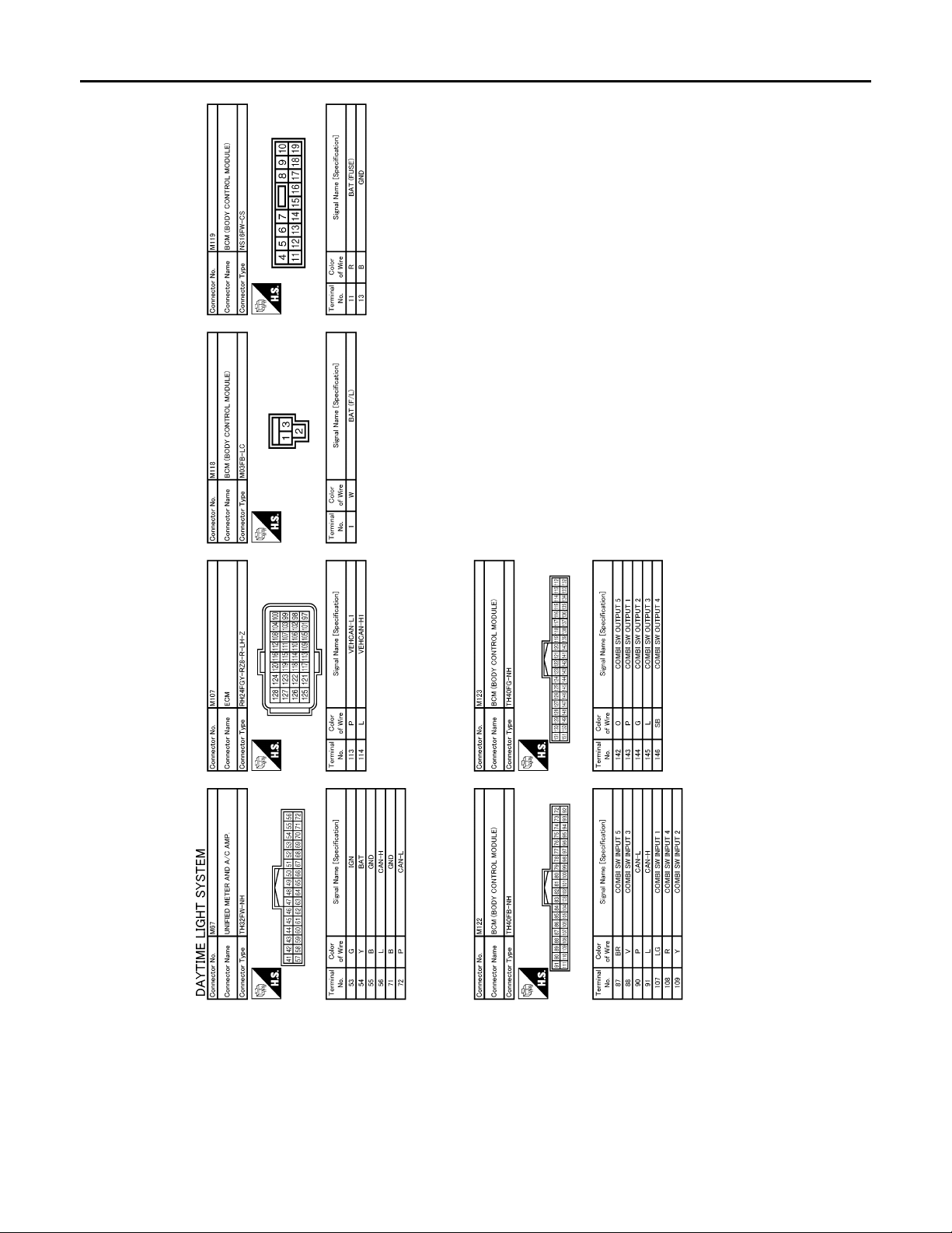
DAYTIME RUNNING LIGHT SYSTEM
B
Revision: 2007 November 2008 EX35
< COMPONENT DIAGNOSIS >
[XENON TYPE]
JCLWM1243G
EXL-100
 Loading...