

Page 1
XJ ENGINE 9 - 1
ENGINE
CONTENTS
page page
GENERAL INFORMATION
ENGINE IDENTIFICATION .................. 1
HYDRAULIC TAPPETS .................... 2
DIAGNOSIS AND TESTING
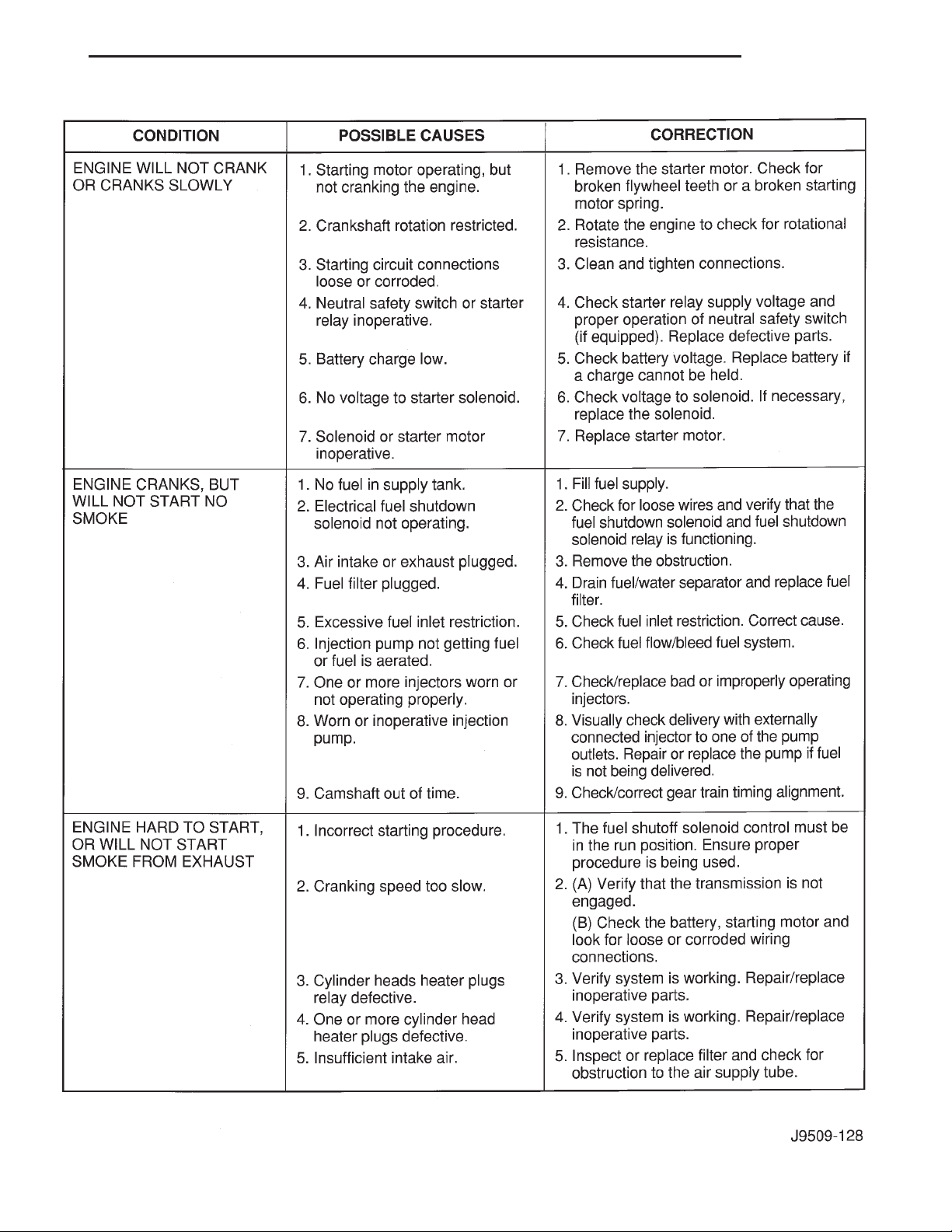
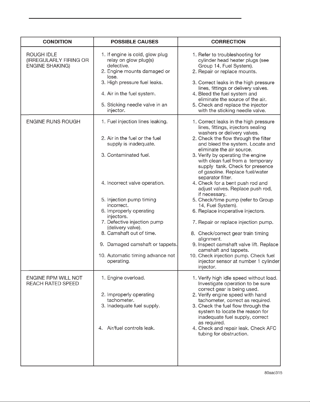
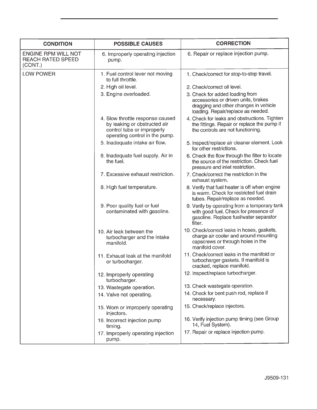
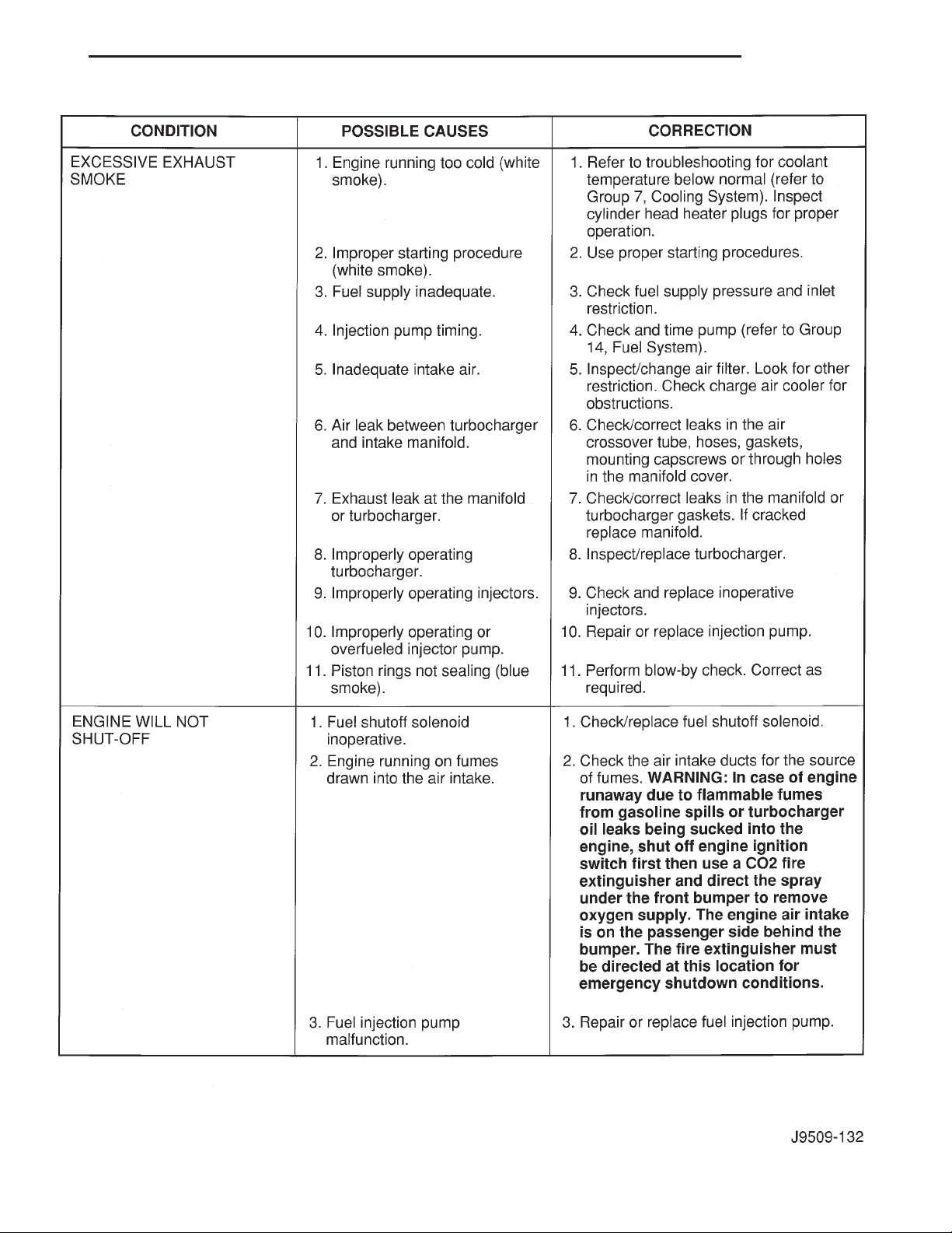
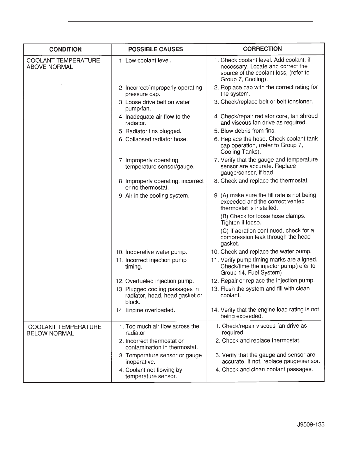
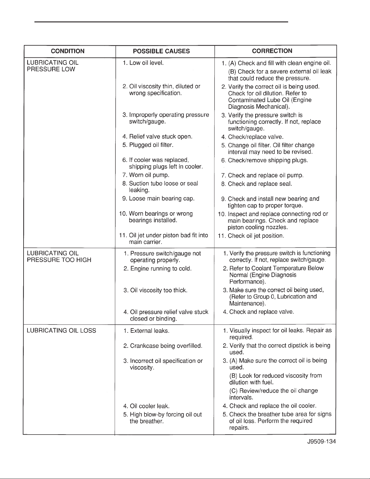
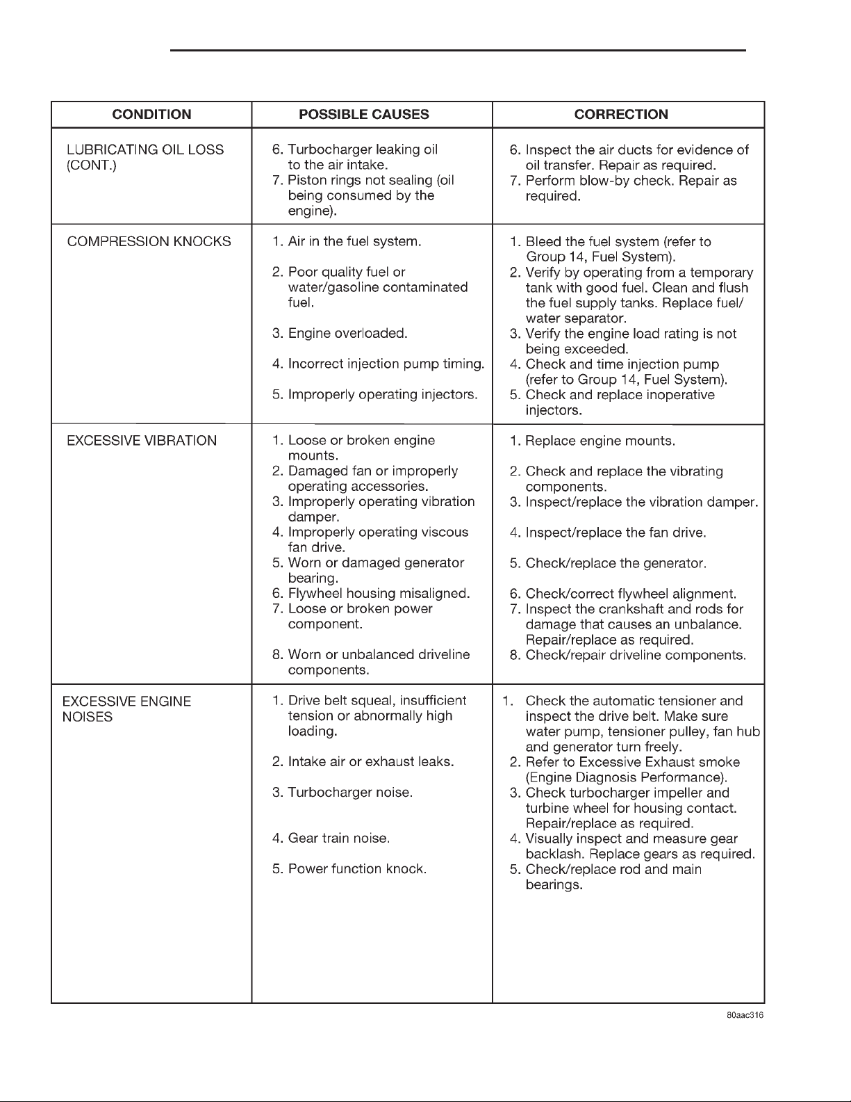
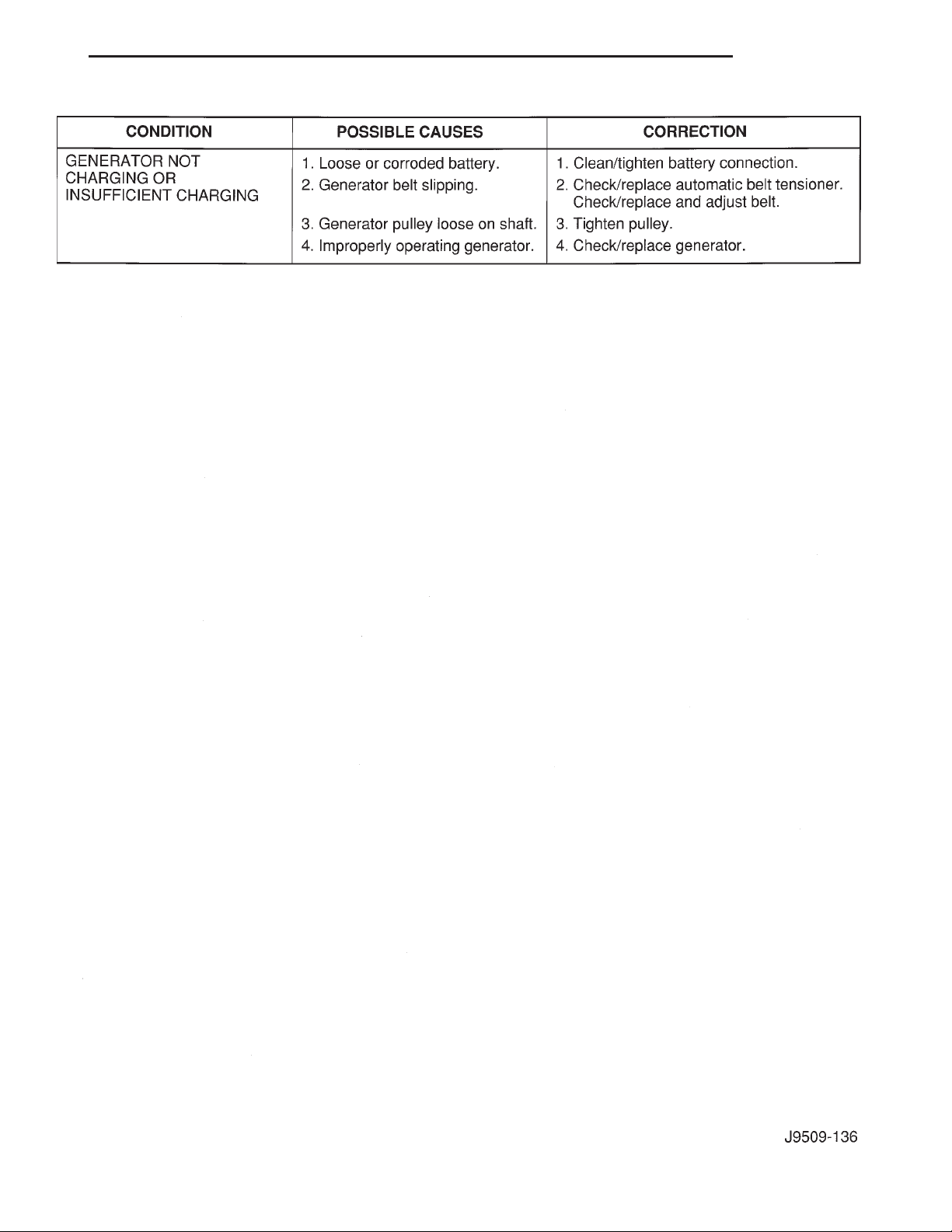
SERVICE DIAGNOSIS—DIESEL—
MECHANICAL ......................... 2
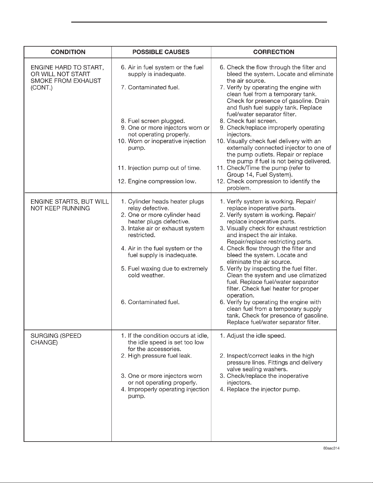
SERVICE DIAGNOSIS—DIESEL—
PERFORMANCE ....................... 2
TAPPET NOISE .......................... 2
SERVICE PROCEDURES
VALVE SERVICE ........................ 12
REMOVAL AND INSTALLATION
2.5L DIESEL ENGINE .................... 18
CAMSHAFT ............................ 30
CAMSHAFT BEARINGS ................... 32
CRANKSHAFT MAIN BEARINGS ............ 39
CYLINDER HEAD COVER ................. 22
CYLINDER WALL LINER ASSEMBLY ........ 37
ENGINE CYLINDER HEAD ................ 25
ENGINE MOUNTS — LHD DIESEL ......... 13
ENGINE MOUNTS — RHD DIESEL ......... 16
HYDRAULIC TAPPETS ................... 23
INTERNAL VACUUM PUMP ............... 33
OIL FILTER ADAPTER .................... 34
OILPAN .............................. 32
OIL PUMP ............................. 32
OIL PUMP PRESSURE RELIEF VALVE ....... 34
PISTONS AND CONNECTING ROD
ASSEMBLY ........................... 35
ROCKER ARMS AND PUSH RODS ......... 24
TIMING GEAR COVER ................... 29
TIMING GEAR COVER OIL SEAL ........... 29
VALVE SPRINGS ........................ 24
VIBRATION DAMPER .................... 29
DISASSEMBLY AND ASSEMBLY
HYDRAULIC TAPPETS ................... 42
CLEANING AND INSPECTION
CYLINDER HEAD ....................... 42
CYLINDER WALL LINER ASSEMBLY ........ 44
OIL PUMP ............................. 45
PISTONS AND CONNECTING ROD
ASSEMBLY ........................... 43
ROCKER ARMS AND PUSH RODS ......... 43
SPECIFICATIONS
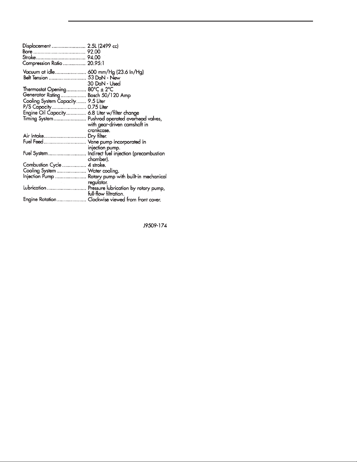
ENGINE SPECIFICATIONS ................. 46
TORQUE SPECIFICATIONS ................ 48
SPECIAL TOOLS
SPECIAL TOOLS ........................ 49
GENERAL INFORMATION
ENGINE IDENTIFICATION
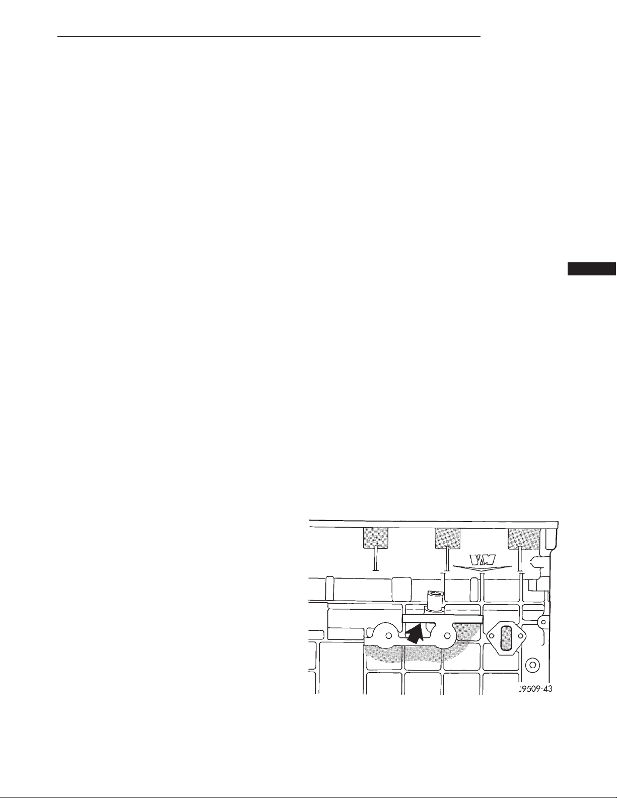
The engine model code and serial number are
stamped on the left side of the engine block, just
below the oil dipstick tube (Fig. 1).
Fig. 1 Engine Code Location
Page 2
9 - 2 ENGINE XJ
GENERAL INFORMATION (Continued)
ate the same tappet action. Check the lubrication
system from the intake strainer to the pump cover,
including the relief valve retainer cap. When tappet
noise is due to aeration, it may be intermittent or
constant, and usually more than 1 tappet will be
noisy. When oil level and leaks have been corrected,
operate the engine at fast idle. Run engine for a sufficient time to allow all of the air inside the tappets
to be bled out.
DIAGNOSIS AND TESTING
SERVICE DIAGNOSIS—DIESEL—
PERFORMANCE
SERVICE DIAGNOSIS—DIESEL—MECHANICAL
TAPPET NOISE
(1) To determine source of tappet noise, operate
engine at idle with cylinder head covers removed.
(2) Feel each valve spring or rocker arm to detect
noisy tappet. The noisy tappet will cause the affected
spring and/or rocker arm to vibrate or feel rough in
operation.
Engine Description
HYDRAULIC TAPPETS
Before disassembling any part of the engine to correct tappet noise, check the oil pressure. If vehicle
has no oil pressure gauge, install a reliable gauge at
the pressure sending unit. The pressure should be
between 4 bars (50 psi) at 3000 RPM.
Check the oil level after the engine reaches normal
operating temperature. Allow 5 minutes to stabilize
oil level, check dipstick. The oil level in the pan
should never be above the FULL mark or below the
ADD OIL mark on dipstick. Either of these 2 conditions could be responsible for noisy tappets:
OIL LEVEL HIGH
If oil level is above the FULL mark, it is possible
for the connecting rods to dip into the oil. With the
engine running, this condition could create foam in
the oil pan. Foam in oil pan would be fed to the
hydraulic tappets by the oil pump causing them to
lose length and allow valves to seat noisily.
OIL LEVEL LOW
Low oil level may allow oil pump to take in air.
When air is fed to the tappets, they lose length which
allows valves to seat noisily. Any leaks on intake side
of oil pump through which air can be drawn will cre-
NOTE: Worn valve guides or cocked springs are
sometimes mistaken for noisy tappets. If such is
the case, noise may be dampened by applying side
thrust on the valve spring. If noise is not appreciably reduced, it can be assumed the noise is in the
tappet. Inspect the rocker arm push rod sockets
and push rod ends for wear.
(3) Valve tappet noise ranges from light noise to a
heavy click. A light noise is usually caused by excessive leak down around the unit plunger or by the
plunger partially sticking in the tappet body cylinder.
The tappet should be replaced. A heavy click is
caused by a tappet check valve not seating or by foreign particles becoming wedged between the plunger
and the tappet body. This will cause the plunger to
stick in the down position. This heavy click will be
accompanied by excessive clearance between the
valve stem and rocker arm as valve closes. In either
case, tappet assembly should be removed for inspection and cleaning.
The valve train generates a noise very much like a
light tappet noise during normal operation. Care
must be taken to ensure that tappets are making the
noise. In general, if more than one tappet seems to
be noisy, its probably not the tappets.
Page 3
XJ ENGINE 9 - 3
DIAGNOSIS AND TESTING (Continued)
Page 4
9 - 4 ENGINE XJ
DIAGNOSIS AND TESTING (Continued)
Page 5
XJ ENGINE 9 - 5
DIAGNOSIS AND TESTING (Continued)
Page 6
9 - 6 ENGINE XJ
DIAGNOSIS AND TESTING (Continued)
Page 7
XJ ENGINE 9 - 7
DIAGNOSIS AND TESTING (Continued)
Page 8
9 - 8 ENGINE XJ
DIAGNOSIS AND TESTING (Continued)
Page 9
XJ ENGINE 9 - 9
DIAGNOSIS AND TESTING (Continued)
Page 10
9 - 10 ENGINE XJ
DIAGNOSIS AND TESTING (Continued)
Page 11
XJ ENGINE 9 - 11
DIAGNOSIS AND TESTING (Continued)
Page 12
9 - 12 ENGINE XJ
SERVICE PROCEDURES
VALVE SERVICE
This procedure is done with the engine cylinder
head removed from the block.
DISASSEMBLY
(1) Remove the engine cylinder head from the cylinder block. Refer to cylinder head removal and
installation in this section.
(2) Use Valve Spring Compressor Tool and compress each valve spring.
(3) Remove the valve locks, retainers, and springs.
(4) Use an Arkansas smooth stone or a jewelers
file to remove any burrs on the top of the valve stem,
especially around the groove for the locks.
(5) Remove the valves, and place them in a rack in
the same order as removed.
VALVE CLEANING
(1) Clean all carbon deposits from the combustion
chambers, valve ports, valve stems, valve stem
guides and head.
(2) Clean all grime and gasket material from the
engine cylinder head machined gasket surface.
INSPECTION
(1) Inspect for cracks in the combustion chambers
and valve ports.
(2) Inspect for cracks on the exhaust seat.
(3) Inspect for cracks in the gasket surface at each
coolant passage.
(4) Inspect valves for burned, cracked or warped
heads.
(5) Inspect for scuffed or bent valve stems.
(6) Replace valves displaying any damage.
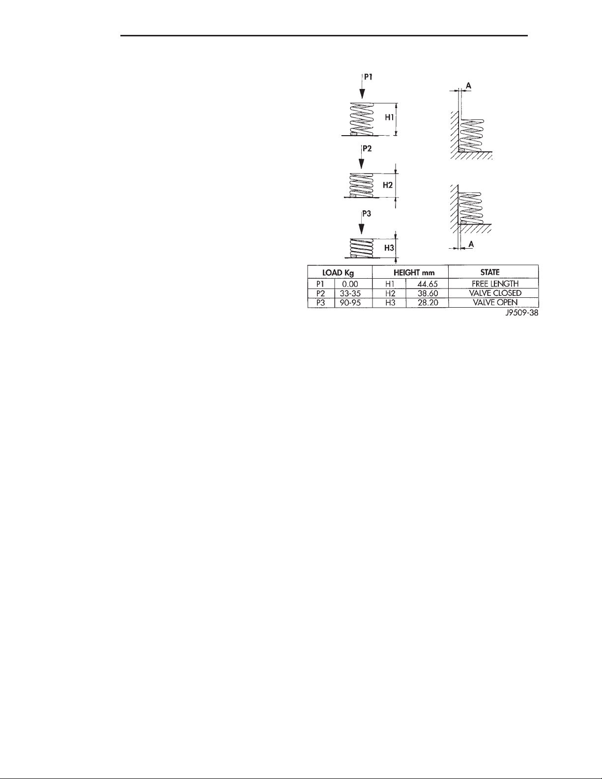
(7) Check valve spring height (Fig. 2).
VALVE REFACING
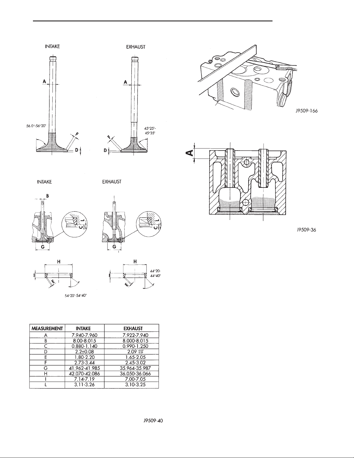
(1) Use a valve refacing machine to reface the
intake and exhaust valves to the specified angle.
(2) After refacing, a margin of at least 4.52-4.49
mm (.178-.177 inch) must remain (Fig. 3). If the margin is less than 4.49 mm (.177 inch), the valve must
be replaced.
VALVE SEAT REFACING
(1) Install a pilot of the correct size in the valve
guide bore. Reface the valve seat to the specified
angle with a good dressing stone. Remove only
enough metal to provide a smooth finish.
(2) Use tapered stones to obtain the specified seat
width when required.
VALVE STAND DOWN
Valve stand down is to maintain the adequate com-
pression ratio.
(1) Invert cylinder head.
(2) Fit each valve to its respective valve guide.
(3) Using a straight edge and feeler gauge (Fig. 4),
check valve head stand down: Inlet valve head stand
down .80 to 1.2 mm (.031 to .047 in.) and exhaust
valve stand down .79 to 1.19 mm (.031 to .047 in).
(4) If valve head stand down is not in accordance
with above, discard original valves, check stand down
with new valves and recut valve seat inserts to
obtain correct stand down.
VALVE GUIDES
(1) Valve Guides height requirement.
(2) Measurement A (Fig. 5): 13.50 - 14.00 mm.
VALVE STEM-TO-GUIDE CLEARANCE MEASUREMENT
(1) Measure and record internal diameter of valve
guides. Valve guide internal diameter is 8.0 to 8.015
mm (.3149 to .3155 ins.).
(2) Measure valve stems and record diameters.
Intake valve stem diameter 7.94 to 7.96 mm (.3125 to
.3133 in). Exhaust valve stem diameter 7.92 to 7.94
mm (.3118 to .31215 in).
(3) Subtract diameter of valve stem from internal
diameter of its respective valve guide to obtain valve
stem clearance in valve guide. Clearance of inlet
valve stem in valve guide is .040 to .075 mm (.0015
to .0029 in). Clearance of exhaust valve stem in valve
guide is .060 to .095 mm (.0023 to .0037 in).
Fig. 2 Valve Spring Chart
Page 13
XJ ENGINE 9 - 13
SERVICE PROCEDURES (Continued)
Fig. 4 Checking Valve Stand Down
Fig. 3 Valve Specification
Fig. 5 Valve Guide Height
(4) If valve stem clearance in valve guide exceeds
tolerances, new valve guides must be installed.
REMOVAL AND INSTALLATION
ENGINE MOUNTS — LHD DIESEL
The engine mounts support the engine at each
side. These supports are made of resilient rubber.
REMOVAL—RIGHT SIDE
(1) Disconnect the negative battery cable.
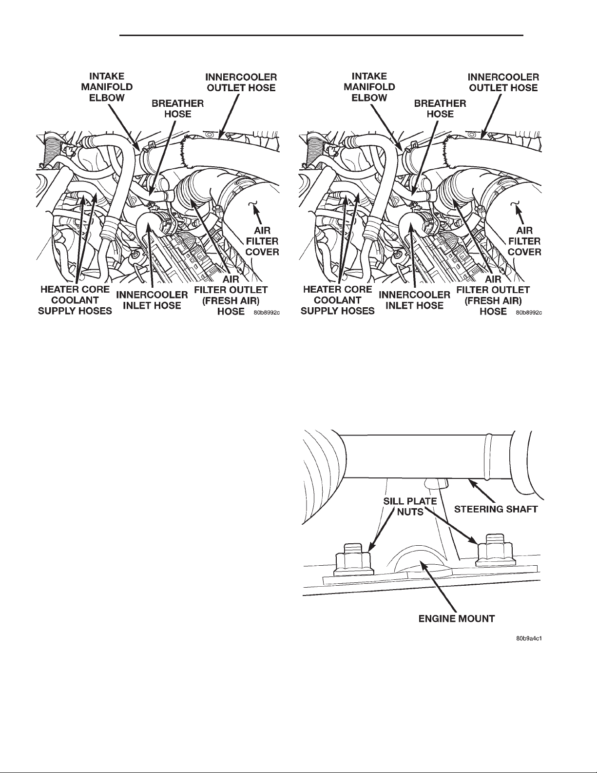
(2) Remove the innercooler inlet hose from the turbocharger and position it out of the way (Fig. 6).
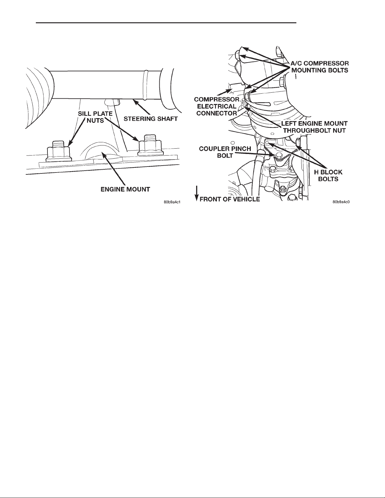
(3) Remove the right engine mount upper sill plate
nuts.
(4) Raise the vehicle on a hoist.
(5) Remove the oil filter and adaptor from the
engine.
(6) Remove the engine mount throughbolt nut only.
Do not remove the bolt at this time.
(7) Position a jack stand and raise the weight off
the right engine mount.
(8) Remove the (2) engine mount lower sill plate
bolts.
(9) Remove the (4) engine mount bracket bolts
from the engine block.
Page 14
9 - 14 ENGINE XJ
REMOVAL AND INSTALLATION (Continued)
Fig. 6 Engine Compartment View — Diesel Fig. 7 Engine Compartment View — Diesel
(10) Remove the engine mount throughbolt.
(11) Remove the right engine mount from the vehi-
cle.
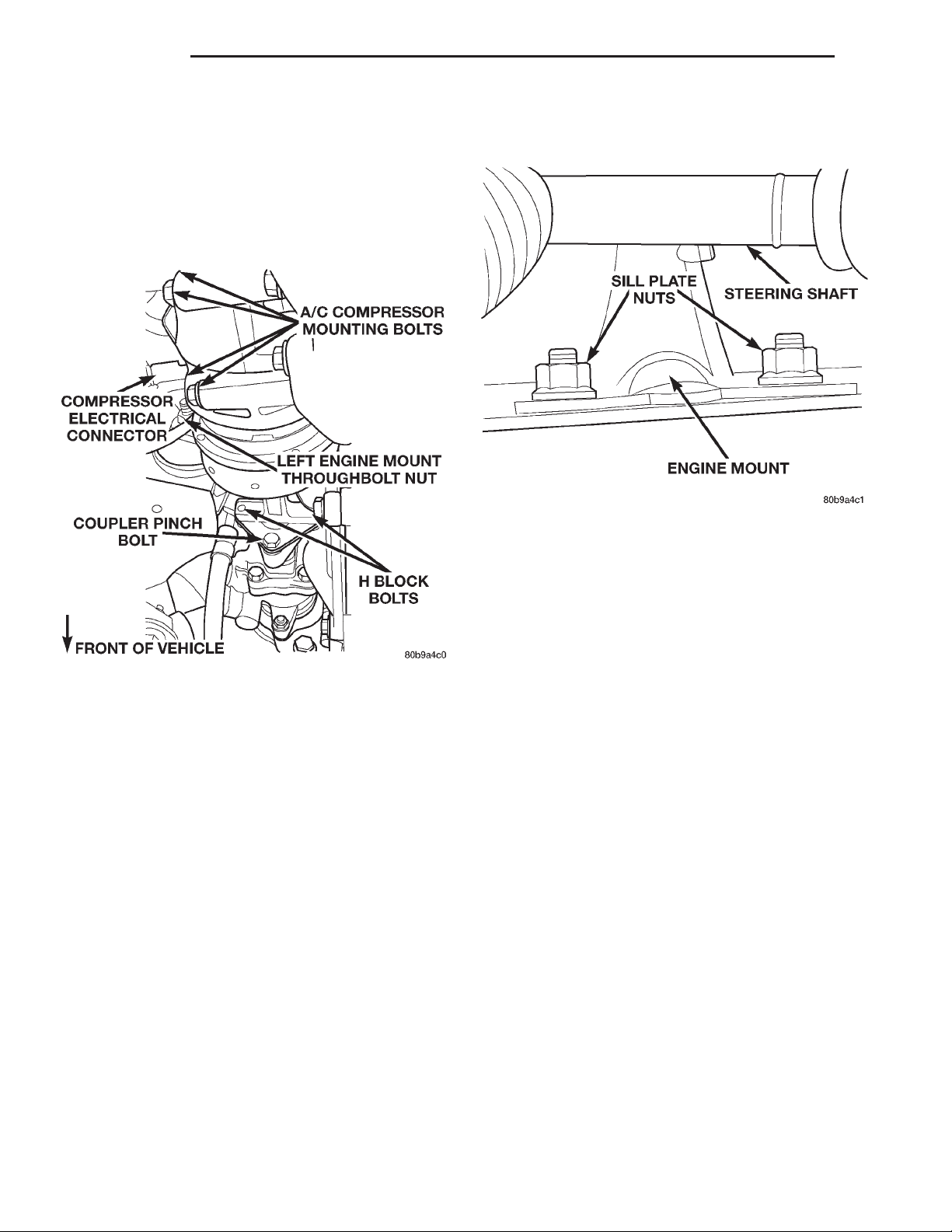
(3) Disconnect the A/C compressor electrical connector.
(4) Remove the (2) engine mount upper sill plate
nuts (Fig. 8).
INSTALLATION—RIGHT SIDE
(1) Position the engine mount and bracket and
install the engine mount throughbolt and nut, leaving them loose at this time.
(2) Install, but do not torque the engine mount
lower sill plate bolts.
(3) Install the (4) engine mount bracket to engine
block retaining bolts and torque to 61 N·m (45 ft.
lbs.).
(4) Torque the engine mount lower sill plate bolts
to 41 N·m (30 ft. lbs.).
(5) Remove the jack stand.
(6) Torque the engine mount throughbolt nut to 65
N·m (48 ft. lbs.).
(7) Install the oil filter and adaptor on the engine.
Torque the adaptor retaining bolt to 50 N·m (37 ft.
lbs.).
(8) Lower the vehicle from the hoist.
(9) Install the engine mount upper sill plate nuts.
Torque to 41 N·m (30 ft. lbs.).
(10) Install the innercooler inlet hose on the turbocharger (Fig. 7).
(11) Connect the negative battery cable.
REMOVAL—LEFT SIDE
(1) Disconnect the negative battery cable.
(2) Remove the refrigerant line support bracket
from the rear of the rocker cover.
position. Raise the vehicle on a hoist.
the shaft from the gearbox by sliding it straight off
the gearbox input shaft.
Fig. 8 Left Engine Mount Sill Plate Nuts
(5) Make sure the steering shaft is in the unlocked
(6) Remove the steering shaft pinchbolt. Remove
Page 15
XJ ENGINE 9 - 15
REMOVAL AND INSTALLATION (Continued)
CAUTION: Do not rotate the steering shaft while
removed from the gearbox input shaft. Damage to
the steering column clockspring will occur.
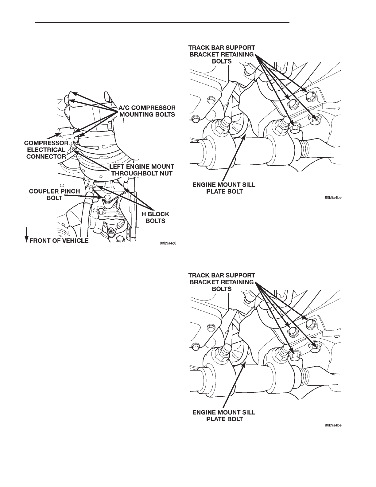
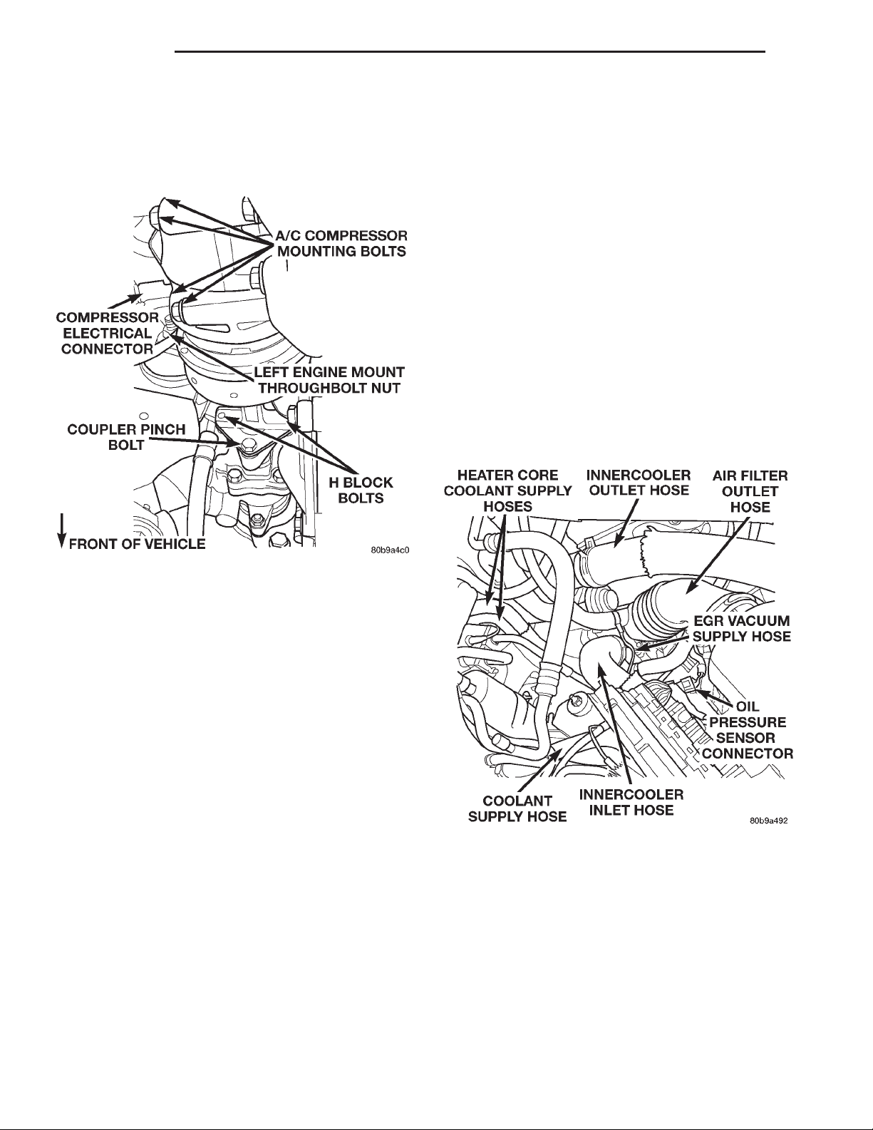
(7) Remove the left engine mount throughbolt nut
only (Fig. 9). Do not remove the bolt at this time.
Fig. 9 A/C Compressor Position & Orientation
(8) Loosen the (4) H-Block retaining bolts, Do not
remove the bolts at this time.
NOTE: Mark the position of the H-Block in relation
to the power steering pump and the A/C Compressor so it may be installed in its original position.
(9) Remove the (2) H-Block retaining bolts from
the power steering pump side of the block (Fig. 9).
(10) Support the A/C Compressor with mechanics
wire before proceeding to the next step.
(11) Remove the (4) A/C Compressor retaining
bolts (Fig. 9).
(12) Remove the remaining (2) bolts from the
H-Block and remove the H-Block from the compressor.
(13) Position a jack stand and raise the weight off
the left engine mount.
(14) Remove the (4) engine mount bracket bolts
from the engine block.
(15) Remove the (4) trackbar support bracket bolts
and remove the bracket (Fig. 10).
(16) Remove the remaining engine mount lower
sill plate bolt (Fig. 10).
(17) Remove the engine mount throughbolt.
(18) Remove the left engine mount from the vehicle.
Fig. 10 Left Engine Mount Retaining Bolts
INSTALLATION—LEFT SIDE
(1) Position the engine mount and bracket and
install the engine mount through bolt and nut, leaving them loose at this time.
(2) Install, but do not torque the engine mount
lower sill plate bolt and the trackbar support bracket
bolts (Fig. 11).
Fig. 11 Left Engine Mount Retaining Bolts
(3) Install the (4) engine mount bracket bolts.
Torque to 61 N·m (45 ft. lbs.).
Page 16
9 - 16 ENGINE XJ
REMOVAL AND INSTALLATION (Continued)
(4) Torque the lower engine mount sill plate bolts
to 41 N·m (30 ft. lbs.) (Fig. 11).
(5) Torque the larger trackbar support bracket
bolts to 125 N·m (92 ft. lbs.) (Fig. 11).
(6) Remove the jack stand.
(7) Position the H-Block and the A/C Compressor
in there original positions and install the retaining
bolts (Fig. 12).
Fig. 12 A/C Compressor Position & Orientation
(8) Torque the A/C Compressor mounting bolts to
41 N·m (30 ft. lbs.) (Fig. 12).
(9) Torque all the H-Block retaining bolts to 18
N·m (159 in. lbs.).
(10) Torque the engine mount throughbolt nut to
65 N·m (48 ft. lbs.) (Fig. 12).
(11) Install the steering shaft. Torque the pinchbolt to 49 N·m (36 ft. lbs.).
(12) Lower the vehicle from the hoist.
(13) Install the engine mount upper sill plate nuts.
Torque to 41 N·m (30 ft. lbs.) (Fig. 13).
(14) Install the refrigerant line support bracket on
the rear of the rocker cover.
(15) Connect the A/C compressor electrical connector.
(16) Connect the negative battery cable.
Fig. 13 Left Engine Mount Sill Plate Nuts
(3) Remove the steering shaft pinchbolt and slide
the steering shaft straight off the gearbox input
shaft.
CAUTION: Do not rotate the steering shaft while
removed from the gearbox input shaft. Damage to
the steering column clockspring will occur.
(4) Remove the oil filter adaptor retaining bolt and
remove oil filter and adaptor from the vehicle.
(5) Remove the engine mount upper sill plate nuts
(Fig. 14).
(6) Remove the engine mount throughbolt nut only.
Leave the bolt installed at this time.
(7) Position a jack stand and raise the weight off
the right engine mount.
(8) Remove the (4) trackbar support bracket
retaining bolts and remove the bracket.
(9) Remove the (4) engine mount bracket bolts
from the engine block.
(10) Remove the remaining engine mount lower
sill plate bolt.
(11) Remove the engine mount through bolt.
(12) Remove the right engine mount from the vehicle.
ENGINE MOUNTS — RHD DIESEL
The engine mounts support the engine at each
side. These supports are made of resilient rubber.
REMOVAL—RIGHT SIDE
(1) Disconnect the negative battery cable.
(2) Make sure the steering wheel is in the
unlocked position. Raise the vehicle on a hoist.
INSTALLATION—RIGHT SIDE
(1) Position the engine mount and bracket in position and install the engine mount through bolt and
nut, leaving them loose at this time.
(2) Install, but do not torque the engine mount
lower sill plate bolts and the trackbar support
bracket bolts.
Page 17
XJ ENGINE 9 - 17
REMOVAL AND INSTALLATION (Continued)
Fig. 14 Right Engine Mount Sill Plate Nuts Fig. 15 A/C Compressor Position & Orientation
(3) Install the (4) engine mount bracket to engine
block retaining bolts. Torque bolts to 61 N·m (45 ft.
lbs.).
(4) Torque the engine mount lower sill plate bolts
to 41 N·m (30 ft. lbs.).
(5) Torque the larger trackbar support bracket
bolts to 125 N·m (92 ft. lbs.).
(6) Install the oil filter and adaptor on the engine.
Torque oil filter adaptor retaining bolt to 50 N·m (75
ft. lbs.).
(7) Remove the jack stand.
(8) Install the engine mount upper sill plate nuts.
Torque to 41 N·m (30 ft. lbs.).
(9) Torque the engine mount throughbolt nut to 65
N·m (48 ft. lbs.).
(10) Install the steering shaft and torque the
pinchbolt to 49 N·m (36 ft. lbs.).
(11) Lower the vehicle from the hoist.
(12) Connect the negative battery cable.
REMOVAL—LEFT SIDE
(1) Disconnect the negative battery cable.
(2) Remove the refrigerant line support bracket
bolt from the upper radiator support crossmember..
(3) Remove the A/C filter-drier assembly support
bracket nuts from the left fenderwell.
(4) Disconnect A/C compressor electrical connector
(Fig. 15).
(5) Raise the vehicle on a hoist.
(6) Remove the engine mount throughbolt nut only
(Fig. 15). Leave the bolt installed at this time.
(7) Loosen the (4) H-Block retaining bolts. Do not
remove the bolts at this time.
NOTE: Mark the position of the H-Block in relation
to the power steering pump and A/C Compressor so
it may be installed in its original position.
(8) Remove the (2) H-Block retaining bolts from
the power steering pump side of the block (Fig. 15).
(9) Support the A/C Compressor with mechanics
wire before proceeding to the next step.
(10) Remove the (4) A/C Compressor mounting
bolts (Fig. 15).
(11) Remove the remaining (2) bolts from H-Block
and remove the H-Block from the compressor.
(12) Position a jack stand and raise the weight off
the left engine mount.
(13) Remove the (2) engine mount upper sill plate
nuts.
(14) Remove the (4) engine mount bracket bolts
from the engine block.
(15) Remove the (2) engine mount lower sill plate
bolts.
(16) Remove the engine mount troughbolt.
(17) Remove the left engine mount from the vehi-
cle.
INSTALLATION—LEFT SIDE
(1) Position the engine mount and bracket in position and install the engine mount through bolt and
nut, leaving them loose at this time.
(2) Install, but do not torque engine mount lower
sill plate bolts.
(3) Install the (4) engine mount bracket to engine
block retaining bolts. Torque to 61 N·m (45 ft. lbs.).
Page 18
9 - 18 ENGINE XJ
REMOVAL AND INSTALLATION (Continued)
(4) Torque the (2) lower engine mount sill plate
bolts to 41 N·m (30 ft. lbs.).
(5) Install the (2) engine mount upper sill plate
nuts. Torque to 41 N·m (30 ft. lbs.).
(6) Remove the jack stand.
(3) Drill out the rivets retaining the hood latch
cable control assembly.
(4) Remove the hood latch assemblies from the
hood.
(5) Disconnect and remove the engine compartment lamp.
(6) With assistance from another person, remove
the hood.
(7) Cover both of the fenders and the grill opening
panel to prevent paint damage.
(8) Remove the battery tray.
(9) Disconnect the radiator cooling fan electrical.
(10) Remove the manual cooling fan and let set
inside of the fan shroud.
(11) If equipped, recover the refrigerant. Refer to
Group 24, Heating and Air Conditioning for the procedure.
(12) Disconnect the suction and discharge lines
and remove the lines from the vehicle.
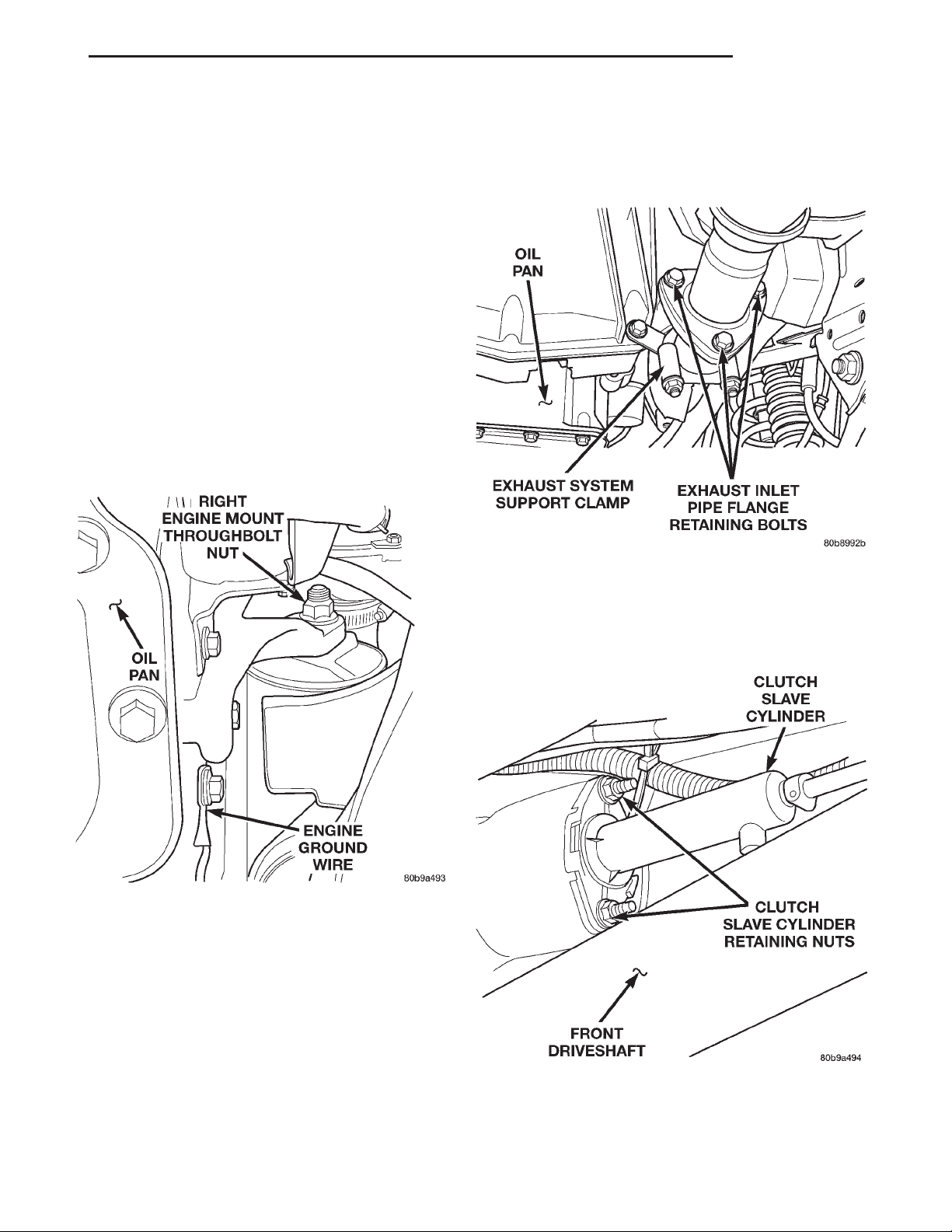
(13) Disconnect the breather hose and remove the
air filter outlet hose from the vehicle (Fig. 17).
Fig. 16 A/C Compressor Position & Orientation
(7) Position the H-Block and the A/C Compressor
in there original positions and install the retaining
bolts (Fig. 16).
(8) Torque the A/C Compressor mounting bolts to
41 N·m (30 ft. lbs.) (Fig. 16).
(9) Torque all the H-Block bolts to 18 N·m (159 in.
lbs.) (Fig. 16).
(10) Torque the engine mount throughbolt nut to
65 N·m (48 ft. lbs.) (Fig. 16).
(11) Lower the vehicle from the hoist.
(12) Install the refrigerant line support bracket.
(13) Install the A/C filter-drier support bracket.
(14) Connect the negative battery cable.
2.5L DIESEL ENGINE
REMOVAL
(1) Disconnect both of the battery cables and
remove the battery.
(2) Mark the hinge locations on the hood for alignment reference during installation.
CAUTION: Wrap the appropriate size drillbit with
masking tape 1/4 inch from tip. This will prevent
damaging the hood outer panel when drilling out
the rivets retaining the hood latch cable control
assembly.
Fig. 17 LHD Engine Compartment — Diesel
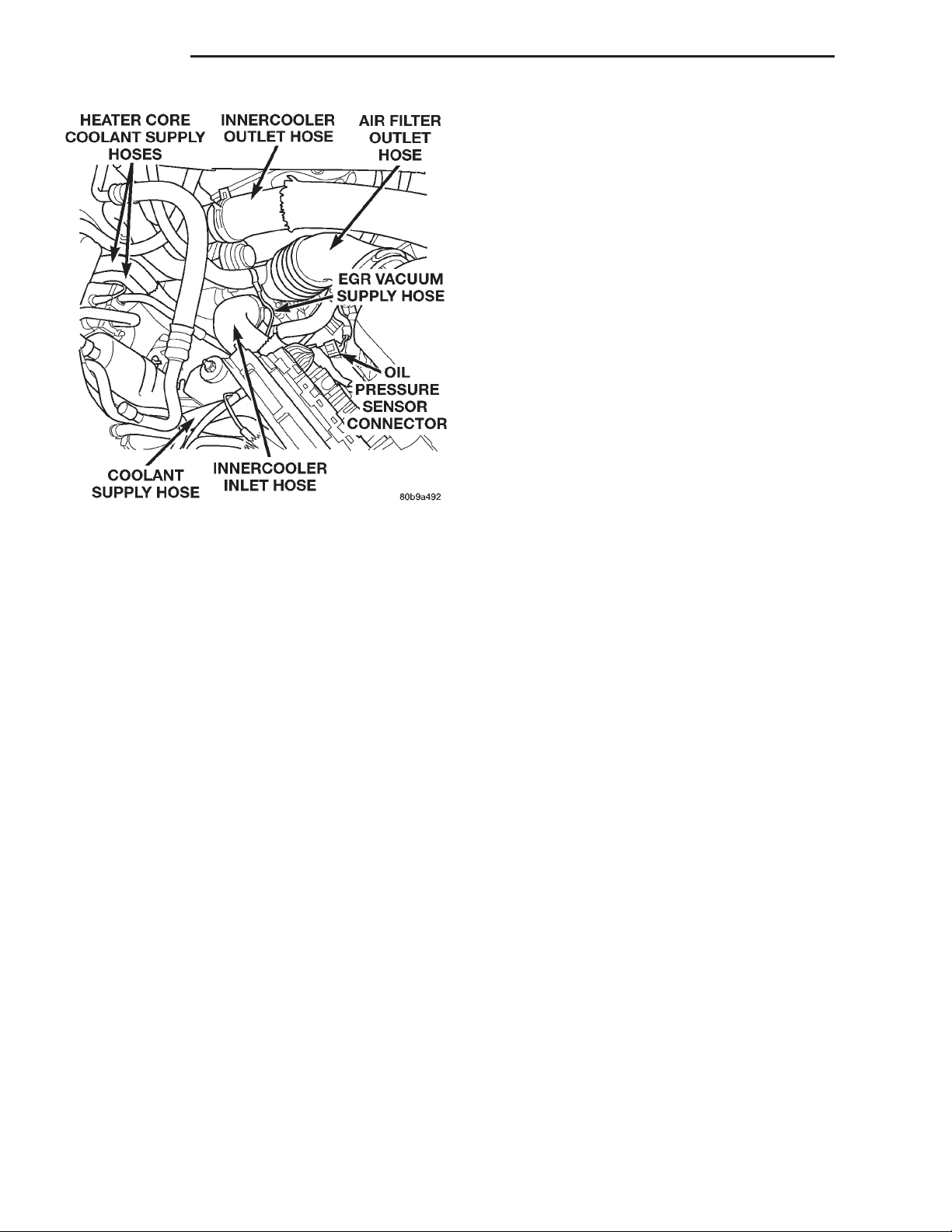
(14) Disconnect the oil pressure sensor electrical
connector (Fig. 17).
(15) Disconnect the EGR vacuum supply hose from
the engine (Fig. 17).
(16) Remove the coolant reservoir cap.
(17) Drain the cooling system. Refer to Group 7,
Cooling System for the procedure.
(18) Remove the upper and lower radiator hoses
from the engine.
(19) Remove the innercooler inlet and outlet hoses
from the engine (Fig. 17).
Page 19
XJ ENGINE 9 - 19
REMOVAL AND INSTALLATION (Continued)
(20) Remove the coolant reservoir supply hose
from the engine (Fig. 17).
(21) On L.H.D. vehicles, disconnect the heater core
coolant supply and the brake vacuum supply hoses
from the engine.
(22) On R.H.D. vehicles, disconnect the heater core
coolant supply and the brake vacuum supply hoses
from the right side of the engine compartment.
Remove the line assembly retaining bolt and bracket
from the rear of the rocker cover and position the
assembly out of the way.
(23) Working inside of the vehicle, remove the center console. Refer to Group 23, Body for the procedure.
(24) Remove the shifter boot seal.
(25) Disconnect the shifter from the transmission
(26) Raise the vehicle on a hoist.
(27) Remove the lower fan shroud retaining bolts
and remove the lower fan shroud panel.
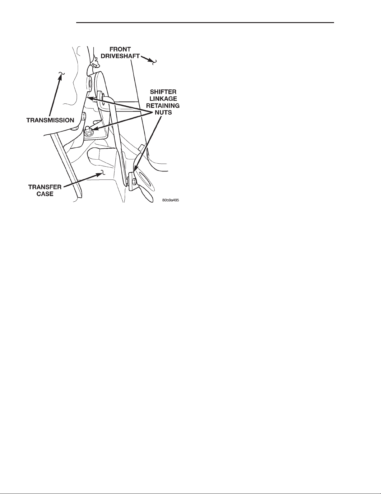
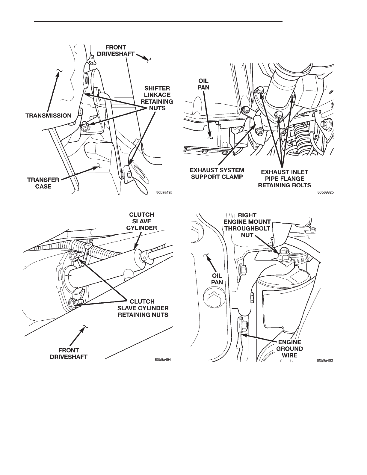
(28) Remove the engine ground wire (Fig. 18).
(34) Disconnect the exhaust system at the (3) bolt
flange (Fig. 19).
Fig. 18 Engine Ground Wire Location
(29) Remove the right and left engine mount
throughbolt nuts only. Do not remove the bolts at
this time (Fig. 18).
(30) Drain the transmission fluid. Refer to Group
21, Transmission and Transfer Case for the procedure.
(31) Mark the position of the front and rear driveshafts in relation to there companion flanges.
(32) Remove the front driveshaft. Refer to Group
3, Differential and Driveline for the procedure.
(33) Remove the rear driveshaft. Refer to Group 3,
Differential and Driveline for the procedure.
Fig. 19 Exhaust System Inlet Pipe Connection
(35) Remove the exhaust system support clamp
(Fig. 19).
(36) Remove the clutch slave cylinder from the
clutch housing (Fig. 20).
Fig. 20 Clutch Slave Cylinder
(37) Remove the (3) nuts retaining the transfer
case shift linkage and position the linkage aside (Fig.
21).
Page 20
9 - 20 ENGINE XJ
REMOVAL AND INSTALLATION (Continued)
(53) Remove the right and left engine mount
throughbolts.
(54) Carefully lift the engine out of the engine
compartment.
INSTALLATION
(1) Carefully place the engine assembly into the
engine compartment..
(2) Install the engine mount throughbolts and nuts
in there original position. Leaving them loose at this
time.
(3) Install the fuel / water separator and mounting
bracket on the bulkhead.
(4) Install the fuel lines on the fuel / water separator.
(5) Connect the electrical connectors to the bottom
of the fuel/water separator.
(6) Install the power steering fluid pressure line
on the steering gear.
(7) Install the oil filter and adaptor on the engine.
Torque adaptor retaining bolt to 50 N·m (37 ft. lbs.).
Fill the oil filter prior to installation.
Fig. 21 Transfer Case Shift Linkage — 4x4
(38) Disconnect the electrical connectors and the
vent hose and from the transfer case and transmission.
(39) Support the rear of the transmission with a
jack.
(40) Remove the transmission support crossmember.
(41) Lower the transmission to gain access to the
transmission to engine retaining bolts.
(42) Remove all the bolts securing the transmission to the engine assembly. Remove the transmission and the transfer case assembly from the vehicle.
(43) Lower the vehicle from the hoist.
(44) Remove the fan shroud and both cooling fans
as an assembly.
(45) Remove the oil filter and adaptor from the
vehicle as an assembly.
(46) Remove the power steering fluid pressure line
from the steering gear.
(47) Disconnect the electrical connectors from the
bottom of the fuel / water separator.
(48) Drain the fuel / water separator. Refer to
Group 9, Fuel System for the procedure.
(49) Remove the fuel lines from the fuel / water
separator and cap.
(50) Remove the fuel / water separator and mounting bracket assembly from the bulkhead.
(51) Remove all the remaining wiring from the
engine assembly and position it out of the way.
(52) Attach a lifting device to the engine lifting
brackets and slightly raise the weight off the engine
mounts.
(8) Install the fan shroud and both cooling fans as
an assembly in the vehicle.
(9) Raise the vehicle on a hoist.
(10) Install the transmission and transfer case
assembly in the vehicle.
(11) Install the bolts securing the transmission to
the engine assembly. Torque to 74.6 N·m (55 ft. lbs.).
(12) Position, connect and secure all electrical connectors and vent hoses on the transfer case and
transmission in there original positions.
(13) Install the transmission support crossmember.
Torque bolts to 50 N·m (37 ft. lbs.).
(14) Install the (3) nuts retaining the transfer case
shift linkage (Fig. 22).
(15) Install the clutch slave cylinder on the clutch
housing, making sure the cylinder pushrod is properly aligned with the clutch fork (Fig. 23).
(16) Connect the exhaust system at the (3) bolt
flange (Fig. 24).
(17) Install the exhaust system support clamp
(Fig. 24).
(18) Install the rear driveshaft in its original position.
(19) Install the front driveshaft in its original position.
(20) Install the lower fan shroud panel and retaining bolt.
(21) Install the engine ground wire (Fig. 25).
(22) Lower the vehicle from the hoist.
(23) Working inside the vehicle, install the shifter
on the transmission
(24) Install the shifter boot seal.
Page 21
XJ ENGINE 9 - 21
REMOVAL AND INSTALLATION (Continued)
Fig. 22 Transfer Case Shift Linkage — 4x4
Fig. 23 Clutch Slave Cylinder
(25) Install the center console. Refer to Group 23,
Body for the procedure.
(26) Position, connect and secure all engine wiring
in its original position
(27) On L.H.D. vehicles, connect the heater core
coolant supply and brake vacuum supply hoses on
the engine.
(28) On R.H.D. vehicles, position the steel line
assembly and connect the heater core coolant supply
and the brake vacuum supply hoses on the engine.
Fig. 24 Exhaust System Inlet Pipe Connection
Fig. 25 Engine Ground Wire Location
(29) Install the coolant reservoir supply hose on
the engine (Fig. 26).
(30) Install the innercooler inlet and outlet hoses
on the engine (Fig. 26).
(31) Install the upper and lower radiator hoses on
the engine.
(32) Fill the cooling system. Refer to Group 7,
Cooling System, for the procedure.
(33) Connect the oil pressure sensor electrical con-
nector (Fig. 26).
Page 22
9 - 22 ENGINE XJ
REMOVAL AND INSTALLATION (Continued)
CYLINDER HEAD COVER
REMOVAL
(1) Disconnect the negative battery cable.
WARNING: DO NOT REMOVE THE CYLINDER
BLOCK DRAIN PLUGS OR LOOSEN THE RADIATOR
DRAIN COCK WITH THE SYSTEM HOT AND PRESSURIZED BECAUSE SERIOUS BURNS FROM THE
COOLANT CAN OCCUR.
(2) On right hand drive vehicles, drain the cooling
system. Refer to Group 7, Cooling System for the procedure.
(3) Recover the air conditioning system, if
equipped. Refer to Group 24, Heating and Air Conditioning for the procedure.
(4) Remove the A/C lines at the compressor and
cap all openings. Refer to Group 24, Heating and Air
Conditioning for the procedure. Remove the A/C line
support bracket attached to cylinder head cover, and
Fig. 26 LHD Engine Compartment — Diesel
(34) Connect the EGR vacuum supply hose on the
engine (Fig. 26).
(35) Install the air filter outlet hose and connect
the breather hose on the engine (Fig. 26).
(36) Install the refrigerant suction and discharge
lines. Torque the retaining bolts on the A/C compressor to 22 Nzm (200 in. lbs.). Make sure the O-Rings
are well lubricated and free of tears.
(37) Charge the refrigerant system. Refer to Group
24, Heating and Air Conditioning for the procedure.
(38) Install the manual cooling fan.
(39) Connect the electric cooling fan electrical connector.
(40) Install the battery tray.
(41) With assistance from another person, install
the hood.
NOTE: Use the previously marked hinge locations
for alignment reference.
(42) Install the hood retaining bolts.
(43) Install the rivets on the hood latch cable control assembly.
(44) Install the hood latch assemblies on the hood.
Install and connect the engine compartment lamp.
(45)
(46) Install the battery and connect both of the
battery cables.
(47) Fill the power steering fluid. Refer to Group
19, Steering — Power Steering Pump-Initial operation for the procedure.
(48) Fill the transmission fluid. Refer to Group 21,
Transmission and Transfer Case for the procedure.
(49) Check the engine oil level before engine start
up.
move the A/C, vacuum lines away from the cylinder
head.
(5) Remove the generator support brace.
(6) Remove the Crankcase breather hose from the
rear of the valve cover
(7) Remove the cylinder head cover bolts.
(8) Remove the cylinder head cover.
INSTALLATION
(1) Install the cylinder head cover. Torque the bolts
to 15 N·m (133 in. lbs.).
(2) Connect the crankcase breather hose.
(3) Install the generator support brace. Torque
bolts to 7 N·m (62 in. lbs.).
(4) Install the A/C lines on the compressor and
install the support bracket on the cylinder head
cover. Torque bolt to 7 N·m (62 in. lbs.).
(5) Connect the negative battery cable.
(6) If equipped with A/C, evacuate and charge the
air conditioning system. Refer to Group 24, Heater
and Air Conditioning.
(7) On right hand drive vehicles, fill the cooling
system. Check for leaks.
WARNING: USE EXTREME CAUTION WHEN THE
ENGINE IS OPERATING. DO NOT STAND IN DIRECT
LINE WITH THE FAN. DO NOT PUT HANDS NEAR
THE PULLEYS, BELTS OR FAN. DO NOT WEAR
LOOSE CLOTHING.
(8) Operate the engine with the radiator cap off.
Inspect for leaks and continue operating the engine
until the thermostat opens. Add coolant, if required.
Page 23
XJ ENGINE 9 - 23
REMOVAL AND INSTALLATION (Continued)
HYDRAULIC TAPPETS
REMOVAL
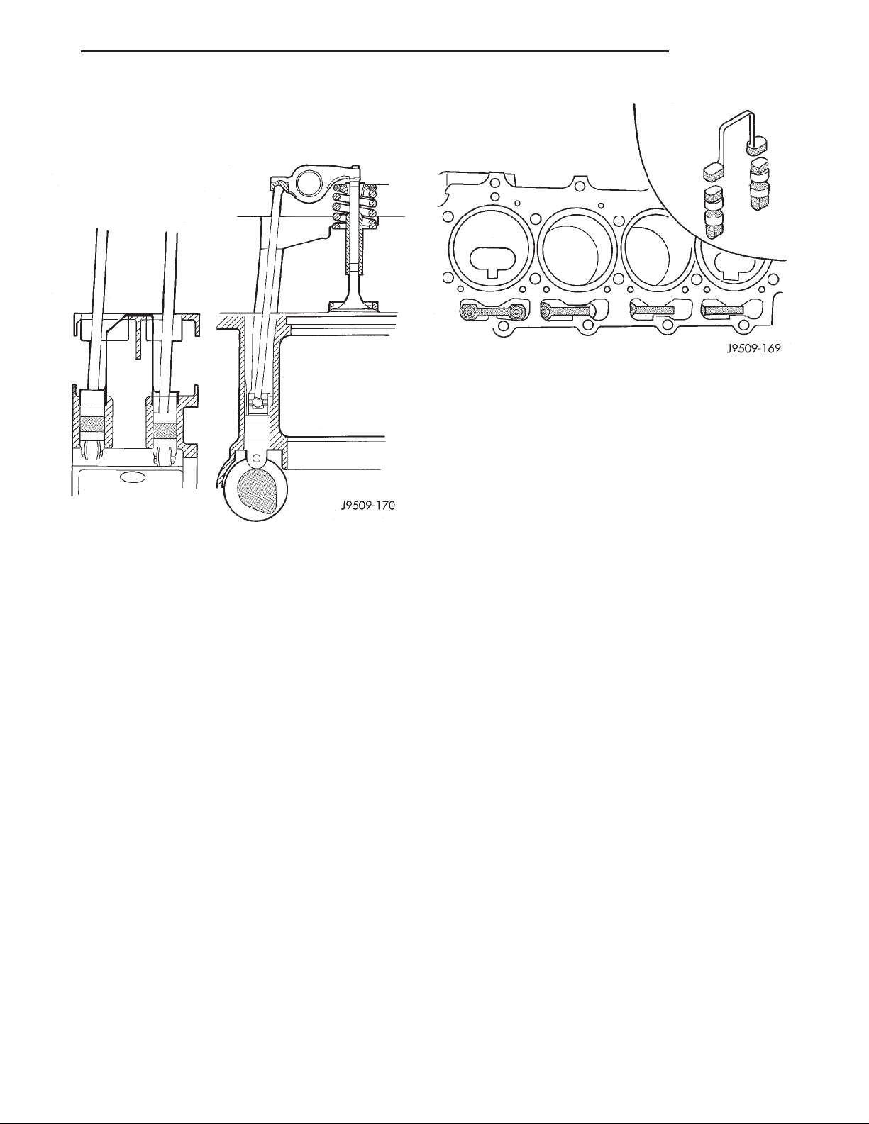
Fig. 28 Tappet And Retainer
CAUTION: The plunger and tappet bodies are not
interchangeable. The plunger and valve must
always be fitted to the original body. It is advisable
to work on one tappet at a time to avoid mixing of
parts. Mixed parts are not compatible. DO NOT disassemble a tappet on a dirty work bench.
Fig. 27 Tappet And Rocker Arm Assembly
(1) Disconnect the negative battery cable.
(2) Discharge the air conditioning system, if
equipped. Refer to Group 24, Heating and Air Conditioning for procedure.
(3) If equipped with air conditioning, remove the
A/C lines at the compressor and cap.
(4) Remove the A/C line bracket attached to the
cylinder head cover and move the lines away from
the cylinder head.
(5) Remove cylinder head cover. Refer to cylinder
head cover removal and installation procedure in this
section.
(6) Remove the rocker assemblies and push rods.
Refer to rocker arms and push rod removal and
installation procedure in this section. Identify push
rods to ensure installation in original location.
(7) Remove cylinder head, intake manifold, and
exhaust manifold. Refer to cylinder head removal
and installation in this section.
(8) Remove the tappet retainers (Fig. 28).
(9) Slide Hydraulic Tappet Remover/Installer Tool
through opening in block and seat tool firmly in the
head of tappet.
(10) Pull the tappet out of the bore with a twisting
motion. If all tappets are to be removed, identify tappets to ensure installation in original location.
INSTALLATION
(1) Lubricate the tappets.
(2) Install the tappets and retainers in their original positions. Ensure that the oil feed hole in the
side of the tappet body faces up (away from the
crankshaft).
(3) Install the cylinder head, intake manifold, and
exhaust manifold. Refer to cylinder head removal
and installation in this section.
(4) Install the push rods.
(5) Install the rocker arms. Refer to rocker arms
and push rod removal and installation in this section.
(6) Install the cylinder head cover. Refer to cylinder head cover removal and installation in this section.
(7) Connect the negative battery cable.
CAUTION: To prevent damage to valve mechanism,
engine must not be run above fast idle until all
hydraulic tappets have filled with oil and have
become quiet.
(8) Start and operate engine. Warm up to normal
operating temperature.
Page 24
9 - 24 ENGINE XJ
REMOVAL AND INSTALLATION (Continued)
ROCKER ARMS AND PUSH RODS
REMOVAL
(1) Disconnect the negative battery cable.
(2) Discharge the air conditioning system, if
equipped. Refer to Group 24, Heating and Air Conditioning for procedure.
(3) If equipped with air conditioning, remove the
service valves and cap the compressor ports. Refer to
Group 24, Heating and Air Conditioning.
(4) Remove the generator bracket.
(5) Remove the cylinder head cover. Refer to cylinder head cover removal and installation in this section.
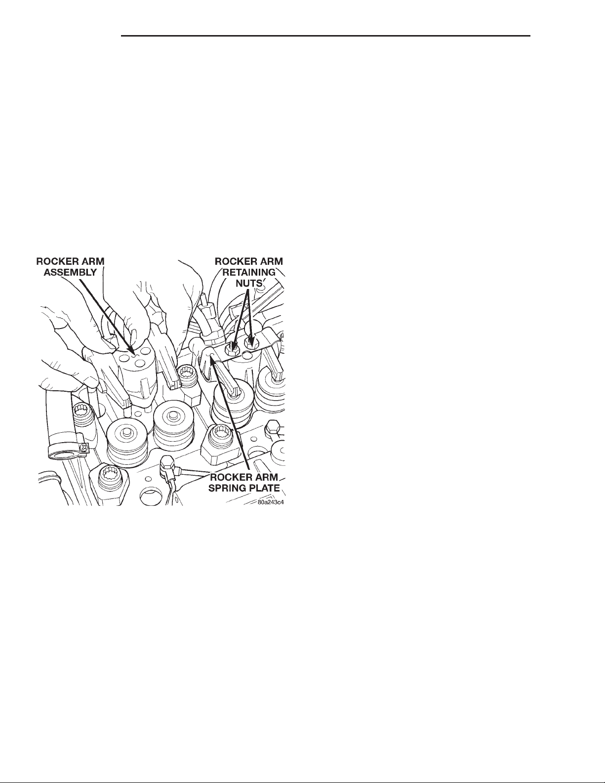
(6) Remove the rocker arm retaining nut (Fig. 29).
Fig. 29 Rocker Arm Retaining Nut
(7) Remove the rocker assembly. Place them on a
bench in the same order as removed.
(8) Remove the push rods and place them on a
bench in the same order as removed.
INSTALLATION
(1) Rotate the crankshaft until the mark lines up
with the TDC mark on the timing cover.
(2) Install the push rods in the same order as
removed.
(3) Install the rocker arm assemblies in the same
order as removed. Torque nuts to 29.4 N·m (264 in.
lbs.).
(4) Install the cylinder head cover. Refer to cylinder head cover removal and installation in this
group.
(5) Install the generator bracket. Torque bolts to 7
N·m (4 ft. lbs.).
(6) If equipped, evacuate and charge the air conditioning system. Refer to Group 24, Heater and Air
Conditioning.
(7) Connect the negative battery cable.
VALVE SPRINGS
This procedure can be done with the engine cylinder head installed on the block.
REMOVAL
(1) Disconnect the negative battery cable.
Each valve spring is held in place by a retainer
and a set of conical valve locks. The locks can be
removed only by compressing the valve spring.
(2) Remove the cylinder head cover. Refer to cylinder head cover removal and installation in this section.
(3) Remove the rocker arms assemblies and push
rods. Refer to rocker arm and push rod removal and
installation in this section. Retain the push rods, and
rocker arms assemblies in the same order and position as removed.
(4) Inspect the springs and retainer for cracks and
possible signs of weakening.
(5) Install an air hose adaptor in the fuel injector
hole.
(6) Connect an air hose to the adapter and apply
air pressure slowly. Maintain at least 621 kPa (90
psi) of air pressure in the cylinder to hold the valves
against their seats.
(7) Tap the retainer or tip with a rawhide hammer
to loosen the lock from the retainer. Use Valve Spring
Compressor Tool to compress the spring and remove
the locks.
(8) Remove the valve spring and retainer.
(9) Inspect the valve stems, especially the grooves.
An Arkansas smooth stone should be used to remove
nicks and high spots.
INSTALLATION
(1) Install the valve spring and retainer.
(2) Compress the valve spring with Valve Spring
Compressor Tool and insert the valve locks. Release
the spring tension and remove the tool. Tap the
spring from side-to-side to ensure that the spring is
seated properly on the engine cylinder head.
(3) Disconnect the air hose. Remove the adaptor
from the fuel injector hole and install the fuel injector.
(4) Repeat the procedures for each remaining valve
spring to be removed.
(5) Install the push rods. Ensure the bottom end of
each rod is centered in the plunger cap seat of the
hydraulic valve tappet.
Page 25
XJ ENGINE 9 - 25
REMOVAL AND INSTALLATION (Continued)
(6) Install the rocker arm assemblies, in their orig-
inal locations. Torque nuts to 29.4 N·m (264 in. lbs.).
(7) Install the cylinder head cover. Refer to cylinder head cover removal and installation in this section.
(8) Connect the negative battery cable.
ENGINE CYLINDER HEAD
REMOVAL
(1) Disconnect the negative battery cable.
WARNING: DO NOT REMOVE THE CYLINDER
BLOCK DRAIN PLUGS OR LOOSEN THE RADIATOR
DRAIN COCK WITH THE SYSTEM HOT AND PRESSURIZED BECAUSE SERIOUS BURNS FROM THE
COOLANT CAN OCCUR.
(2) Drain the cooling system. Refer to Group 7,
Cooling System for procedure.
(3) Discharge the air conditioning system, if
equipped. Refer to Group 24, Heating and Air Conditioning for procedure.
(4) If equipped with air conditioning, remove the
A/C lines at the compressor and cap. Refer to Group
24, Heating and Air Conditioning. Remove A/C line
bracket attached to cylinder head cover, and move
A/C lines away from cylinder head.
(5) Remove the air cleaner hose from turbocharger
and breather hose.
(6) Remove the air cleaner assembly and breather
hose.
(7) Remove the generator support bracket.
(8) Remove the upper radiator hose and coolant
recovery hose.
(9) Remove the water manifold and recovery hose.
(10) Disconnect the heater hoses and coolant
recover bottle hose.
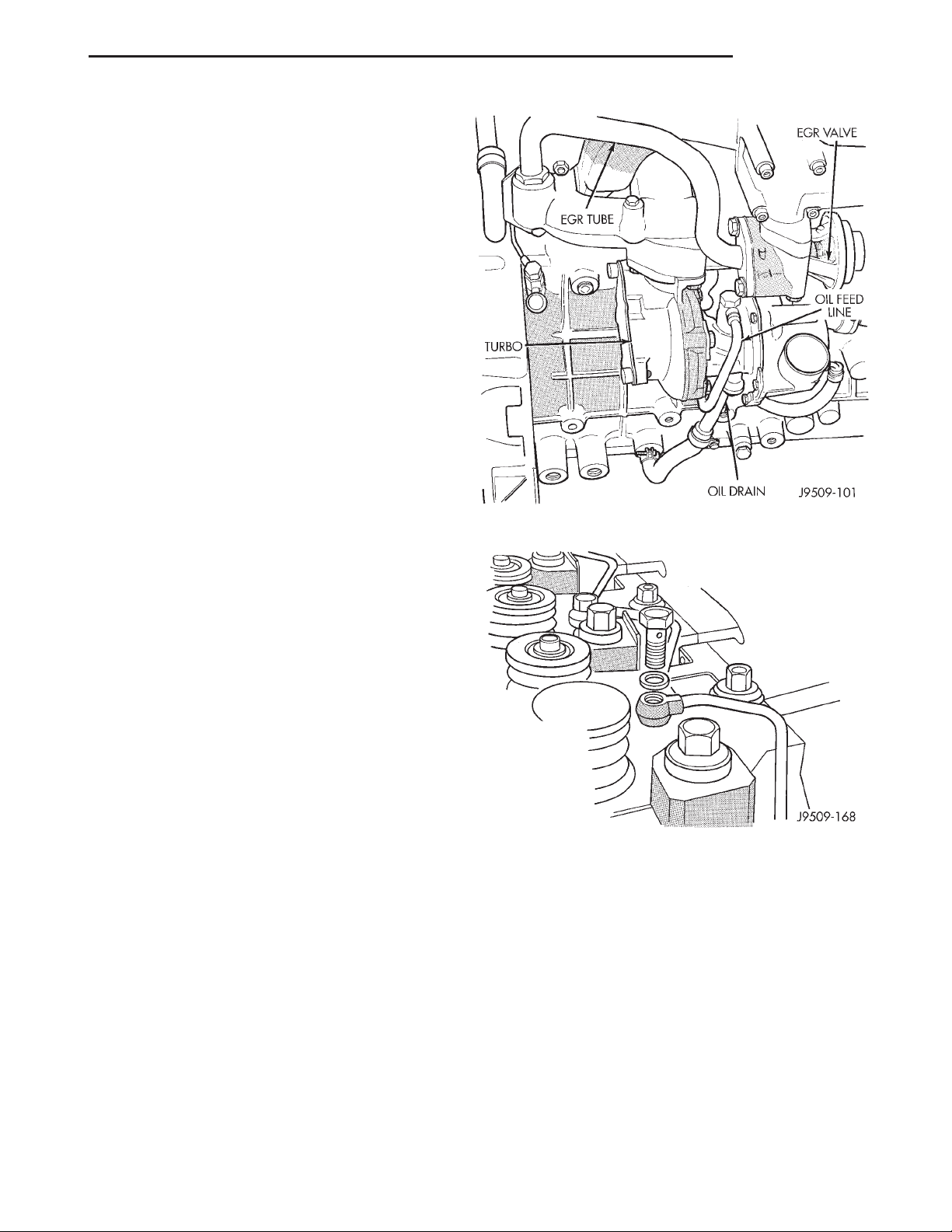
(11) Disconnect the EGR tube from EGR valve.
(12) Remove the EGR valve
(13) Remove the exhaust heat shield from exhaust
manifold.
(14) Remove the exhaust heat shield from down
pipe.
(15) Remove the exhaust down pipe from turbocharger (Fig. 30).
(16) Disconnect the oil feed line from turbocharger.
(17) Disconnect the oil drain line from turbocharger.
(18) Remove the Exhaust manifold. Refer to Group
11, Exhaust System and Turbocharger.
(19) Remove the Intake manifold. Refer to intake
manifold removal and installation procedure in this
section.
(20) Remove the oil feed line for rocker arm
assemblies (Fig. 31).
Fig. 31 Rocker Arm Oil Feed Lines
(21) Remove the Crankcase breather hose from
rear of the valve cover
(22) Remove the injector sensor wire and the glow
plug hot lead.
(23) Remove the fuel lines and fuel filter. Refer to
Group 14, Fuel Systems for procedure.
(24) Remove the injector fuel lines from injectors
to pump.
(25) Remove the fuel injectors with tool VM.1012
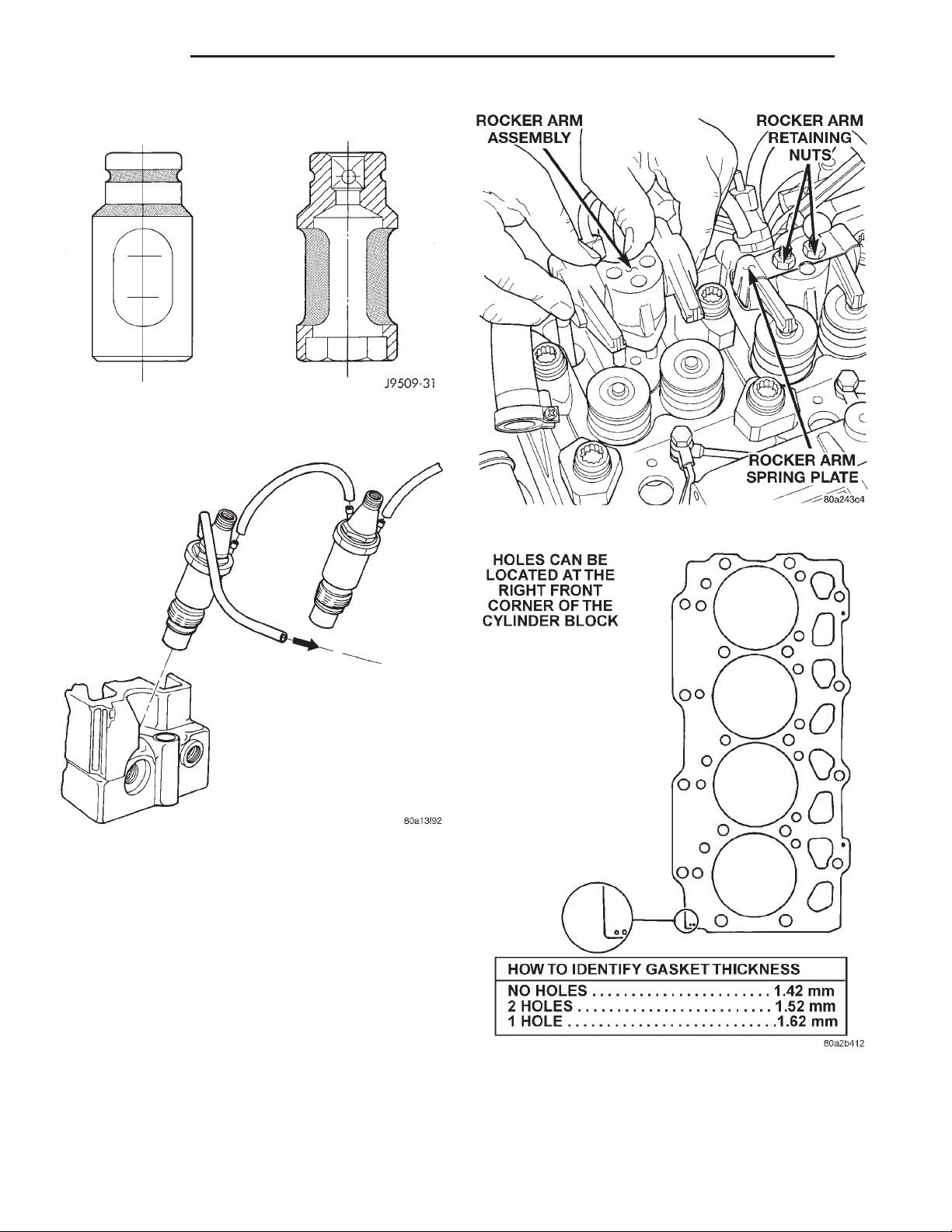
(Fig. 32). Refer to Group 14, Fuel System for procedure.
(26) Remove the engine cylinder head cover.
(27) Remove the rocker retaining nuts (Fig. 34).
(28) Remove the rocker arm assemblies. Place
them on a bench in the same order as removed.
Fig. 30 Turbocharger
Page 26
9 - 26 ENGINE XJ
REMOVAL AND INSTALLATION (Continued)
Fig. 32 Fuel Injector Tool VM.1012
Fig. 33 Fuel Injector
(29) Remove the push rods and place them on a
bench in the same order as removed.
(30) Mark the cylinder head positions.
(31) Remove the engine cylinder head bolts with
special tool VM.1018 and VM.1019.
(32) Remove the engine cylinder head and gasket.
(33) Stuff clean lint free shop towels into the cyl-
inder bores.
Fig. 34 Rocker Arm Retaining Nuts
CYLINDER HEAD GASKETS
A steel cylinder head gasket is used for all four cyl-
inder heads.
Cylinder head gaskets are available in three thicknesses. Identification holes in the right front corner
of the gasket indicate the thickness of the gasket
(Fig. 35).
Fig. 35 Steel Type Cylinder Head Gasket—
identification
CAUTION: Piston protrusion must be measured, to
determine cylinder head gasket thickness, if one or
more cylinder wall liners have been replaced.
Page 27
XJ ENGINE 9 - 27
REMOVAL AND INSTALLATION (Continued)
NOTE: If cylinder wall liners have not been
removed; the same thickness head gasket removed,
may be used.
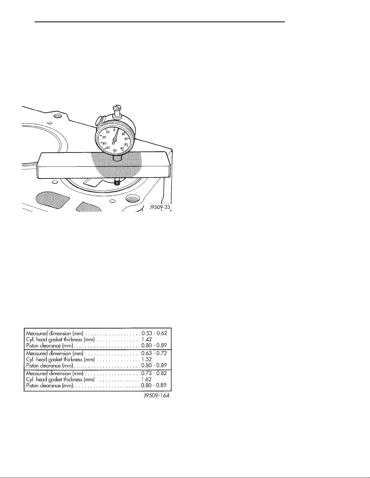
MEASURING PISTON PROTRUSION
(1) Use special tool VM.1010 with dial indicator
special tool VM.1013 (Fig. 36).
Fig. 36 Measuring Piston Protrusion
(2) Bring the piston of cylinder no. 1 exactly to top
dead center.
(3) Zero the dial indicator on the cylinder block
mating surface.
(4) Setup the dial indicator on the piston crown
(above the center of the piston pin) 5mm (1/8 in.)
from the edge of the piston and note the measurement (Fig. 37).
(5) Repeat the procedure with the rest of the cylinders.
(6) Establish the thickness of the steel gasket for
all four cylinder heads on the basis of the greatest
piston protrusion (Fig. 35).
INSTALLATION
(1) Remove the shop towels from the cylinder
bores. Coat the bores with clean engine oil.
(2) Install cylinder head alignment studs VM.1009.
(3) After determining the correct head gasket
thickness, clean the block and head mating surfaces,
place the engine cylinder head gasket over the alignment studs.
(4) Place the engine cylinder head over the alignment studs.
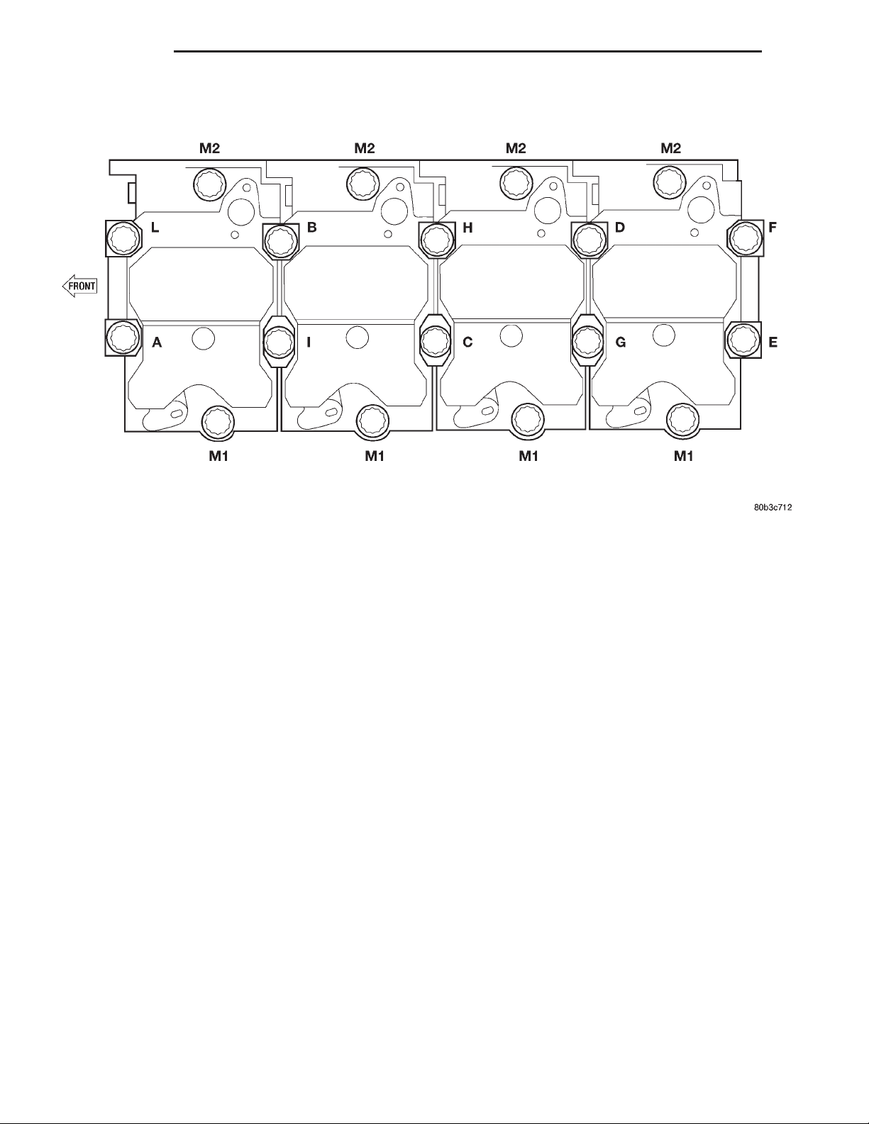
CAUTION: New cylinder head bolts should be used.
(5) Tighten the engine cylinder head bolts in
sequence according to the following procedure (Fig.
38):
a. The threads and underside heads of the bolts
should be lubricated. Use the cylinder head alignment studs tool number VM-1009. Position the heads
on the block and secure with the ten large center
bolts and spacers (clamps), finger tight only.
b. Ensure that the various clamps are installed
correctly and the head gasket remains in it’s proper
position, completely covered. Then, lubricate and
install the eight small bolts, also finger tight.
(6) Install the intake and exhaust manifolds with
a new gasket, partially tightening the nuts to a maximum of 5 N·m (44 in. lbs.). This will align the heads.
Refer to Group 11, Exhaust System and Turbocharger for the proper procedure. Install lift eye and
brake vacuum tube at this time.
(7) Then, tighten the 12mm bolts with special tool
VM.1019 in the following manner:
(8) 1st Phase: Tightening Head Bolts (Fig. 38).
Central bolts (A-L): Tighten all bolts, starting with
bolt H then G-F-E-D-C-B-A-L-I, to 30 N·m. Tighten
all bolts an additional 70°, starting with bolt A and
continuing in alphabetical order. Finally, tighten all
bolts an additional 70°, starting again with bolt A
and continuing in alphabetical order.
(9) Tighten the 14mm bolts in the following manner:
(10) Side bolts (M1-M2): Tighten M1 bolts to 30
N·m, then rotate them 85° (65). Tighten M2 bolts to
30 N·m, then rotate them 85° (65).
Fig. 37 Piston Protrusion Chart
CAUTION: Gaskets are to be installed DRY. DO NOT
use a gasket sealing compound on the gasket.
NOTE: If vehicle is equipped with A/C do not install
A/C lines to compressor and charge A/C till Phase 2
is complete.
(11) 2nd Phase: After 20 minutes of engine operation at operating temperature, allow engine to cool
down completely. Then retorque the head bolts as follows:
(12) Central bolts A-L: Completely back off bolts
one-by-one and then retighten to 30 N·m plus 130°
(65°). Then proceed in the same way, bolt by bolt,
following alphabetical order, as indicated.
Page 28
9 - 28 ENGINE XJ
REMOVAL AND INSTALLATION (Continued)
Fig. 38 Engine Cylinder Head Bolt Tightening Sequence
(13) Side bolts M1-M2: Without slackening,
torque bolts M1 then bolts M2 to 90 N·m (66 ft. lbs.).
(14) Torque intake nuts to 32 N·m (24 ft. lbs.) and
exhaust manifolds nuts to 32 N·m (24 ft. lbs.) after
completing the cylinder head torquing procedure.
NOTE: If the engine cylinder head is to be replaced
and the original valves used, measure the valve
stem diameter. Only standard size valves can be
used with a service replacement engine cylinder
head unless the replacement head valve stem guide
bores are reamed to accommodate oversize valve
stems. Remove all carbon buildup and reface the
valves.
(15) Install the oil feed lines for the rocker arm
assemblies and oil pressure switch. Torque oil feed
lines to 13 N·m (115 in. lbs.).
(16) Install the push rods and rocker arm assemblies, tighten nuts to 29 N·m (22 ft. lbs.).
(17) Install the cylinder head cover. Torque bolts to
15 N·m (133 in. lbs.).
(18) Connect the crankcase breather hose.
(19) Connect the injector sensor wire and the glow
plug hot lead.
(20) Install the turbocharger oil feed line. Torque
banjo bolts to 27 N·m (20 ft. lbs).
(21) Install the turbocharger oil drain line. Torque
bolts to 11 N·m (97 in. lbs.).
(22) Install the water manifold. Torque bolts to 12
N·m (106 in. lbs.).
(23) Install the generator support bracket.
(24) Raise the vehicle on hoist.
(25) Install the exhaust down pipe to turbocharger,
tighten bolts to 22 N·m (16 ft. lbs.).
(26) Install the exhaust down pipe heat shield.
(27) Install the exhaust heat shield, Tighten bolts
to 11 N·m (8 ft. lbs.).
(28) Install the EGR valve to intake manifold,
tighten bolts to 26 N·m (19 ft. lbs.).
(29) Install the EGR tube to EGR valve, tighten
bolts to 26 N·m (19 ft. lbs.).
(30) Install the lower Charge air cooler hose to tur-
bocharger.
(31) Install the air cleaner assembly and hose.
(32) Install the oil breather hose to air cleaner
hose.
(33) Install the upper charge cooler hose to turbo-
charger.
(34) Connect the recover bottle hose to water man-
ifold.
(35) Install the fuel injectors using special tool
VM.1012. Refer to Group 14, Fuel System for procedures.
(36) Install the fuel injector lines from the pump
to injectors. Torque nuts to 23 N·m (17 ft. lbs.).
(37) Connect the A/C lines to compressor and
install bracket on cylinder head cover, if equipped
with air conditioning.
Page 29
XJ ENGINE 9 - 29
REMOVAL AND INSTALLATION (Continued)
(38) Install the fuel filter, Tighten bolts to 28 N·m
(250 in. lbs.)
(39) Connect the fuel supply and return lines
(40) Connect the upper radiator hose.
(41) Connect the negative cable battery.
(42) If equipped with A/C, evacuate and charge the
air conditioning system. Refer to Group 24, Heater
and Air Conditioning.
(43) Fill the cooling system. Check for leaks.
WARNING: USE EXTREME CAUTION WHEN THE
ENGINE IS OPERATING. DO NOT STAND IN DIRECT
LINE WITH THE FAN. DO NOT PUT HANDS NEAR
THE PULLEYS, BELTS OR FAN. DO NOT WEAR
LOOSE CLOTHING.
(44) Operate the engine with the radiator cap off.
Inspect for leaks and continue operating the engine
until the thermostat opens. Add coolant, if required.
CAUTION: After rebuild or cylinder head gasket
replacement, the cylinder head must be retorqued
within the first 20,000km. If individual fiber type
head gaskets were used.
(3) Install the accessary drive belt. Refer to Group
7, Cooling System for procedure.
(4) Connect the negateive battery cable.
TIMING GEAR COVER OIL SEAL
REMOVAL
(1) Disconnect the negative battery cable.
(2) Remove the vibration damper. Refer to vibra-
tion damper removal and installation in this section.
CAUTION: Use care when removing the old seal.
Be sure not to damage the timing gear cover.
(3) Pry out the old seal.
INSTALLATION
Remove the oil seal ring. The seating diameter
must be 68.000 - 68.030 mm.
(1) Install the new seal using special tool
VM.1015A.
(2) Install the vibration damper. Refer to vibration
damper removal and installation in this section.
(3) Connect the negative battery cable.
NOTE: The one piece steel type head gasket does
not require, the above mentioned, retorque procedure.
CYLINDER HEAD RE-TORQUE
Within the first 20,000 km (12,000 miles) after
rebuild, retorque the cylinder head bolts as follows:
(Fig. 38) Central bolts A-L: Without slackening the
bolts, following alphabetical order tighten the bolts
through an angle of 15°. Side bolts M1-M2: Without
slackening, tighten M1 then M2 bolts through an
angle of 15°.
VIBRATION DAMPER
REMOVAL
(1) Disconnect the negative battery cable.
(2) Remove the fan and set fan inside fan shroud
then remove fan shroud and fan as an assembly.
(3) Remove the accessary drive belt. Refer to
Group 7, Cooling System for procedure.
(4) Remove the vibration damper nut.
(5) Install special tool VM.1000-A to remove vibration damper.
INSTALLATION
(1) Install the vibration damper and align with
key way.
(2) Install the vibration damper nut. Torque nut to
196 N·m (147 ft. lbs.).
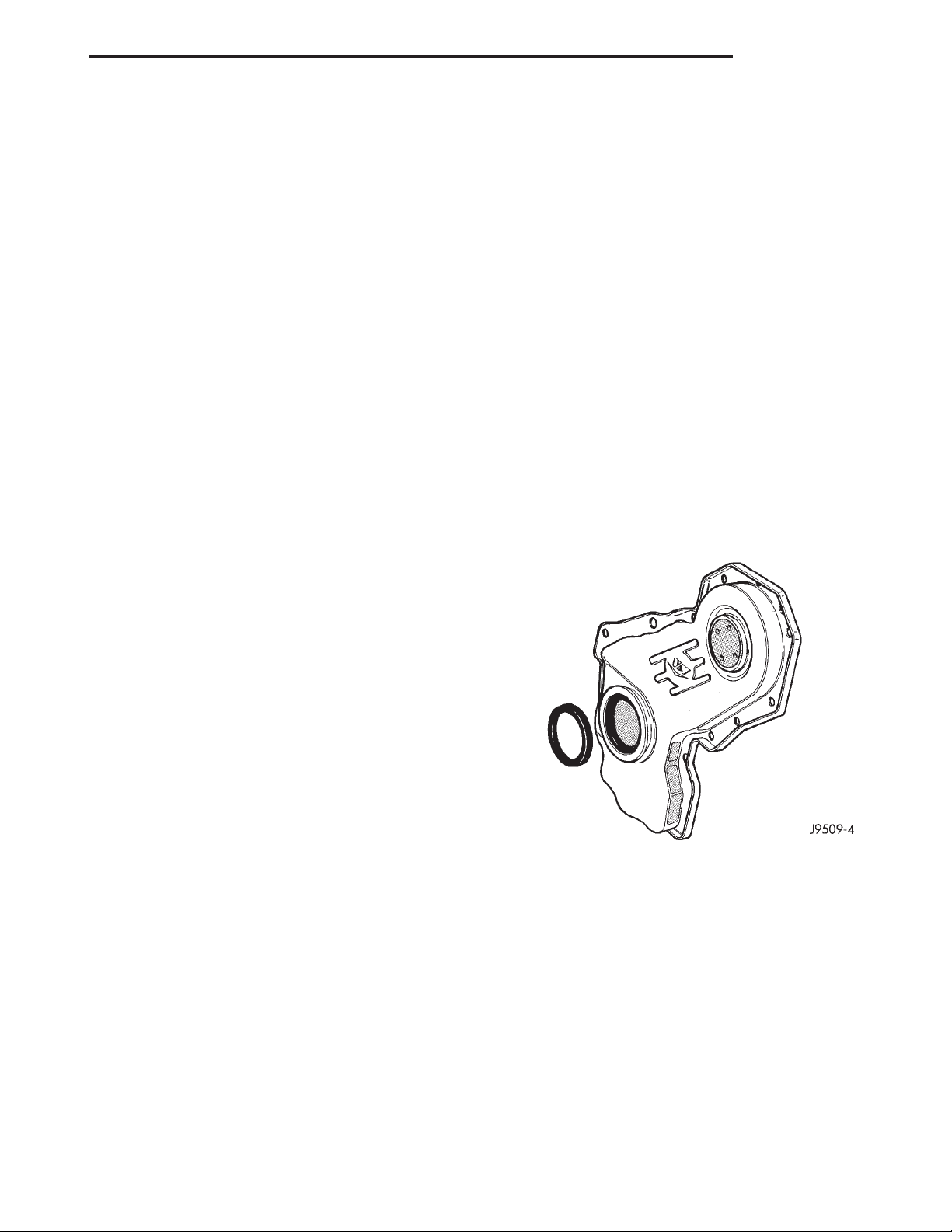
Fig. 39 Timing Gear Cover Oil Seal
TIMING GEAR COVER
REMOVAL
(1) Disconnect the negative battery cable.
(2) Remove the fan and set fan inside fan shroud
then remove fan shroud and fan as an assembly.
(3) Remove the accessary drive belt. Refer to
Group 7, Cooling System for procedure.
(4) Remove the vibration damper nut.
(5) Install special tool VM.1000-A to remove the
vibration damper.
(6) Remove the fan pulley.
NOTE: The idler pulley bolt has left hand thread.
Page 30
9 - 30 ENGINE XJ
REMOVAL AND INSTALLATION (Continued)
(7) Remove the idler pulley and bracket.
(8) Remove the automatic belt tensioner.
(9) Remove the Power steering pump pulley.
(10) Remove the timing gear cover.
INSTALLATION
(1) Be sure the mating surfaces of the gear case
cover and the cylinder block are clean and free from
burrs.
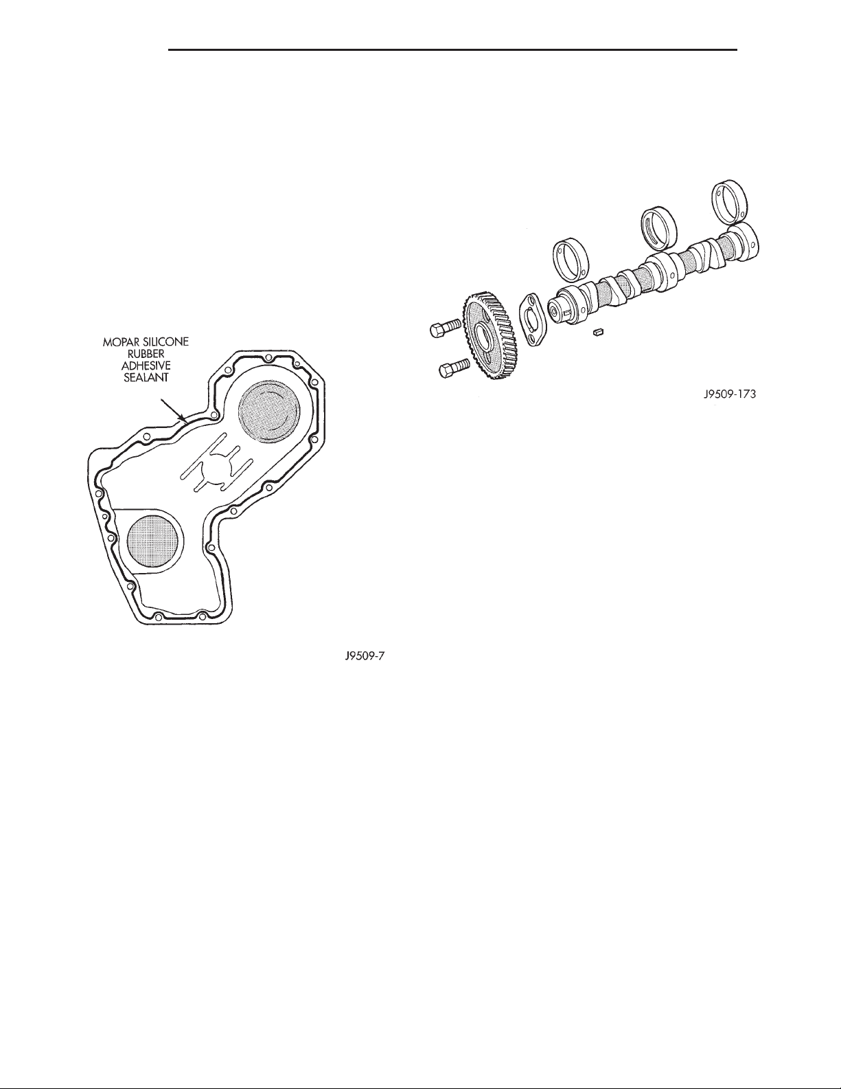
(2) Apply a continuous 3 mm bead of Silicone
Sealer (Fig. 40) to timing cover, install within 10
minutes, tighten 6mm bolts to 10.3 N·m (91 in. lbs)
and tighten 8mm bolts to 26.2 N·m (19 ft. lbs.).
Fig. 40 Front Cover Sealer Location
(3) Install Power steering pump pulley. Torque nut
to 130 N·m (96 ft. lbs.).
(4) Install the automatic belt tensioner.
(5) Install the idler pulley bracket. Torque bolts to
40 N·m (29 ft. lbs.).
NOTE: The idler pulley has left hand thread.
(6) Install the idler pulley. Torque nut to 48 N·m
(35 ft. lbs.).
(7) Install the fan pulley. Torque bolts to 56 N·m
(41 ft. lbs.).
(8) Install the vibration damper. torque nut to 196
N·m (147 ft. lbs.).
(9) Install the accessary drive belt. Refer to Group
7, Cooling System for procedure).
(10) Install the fan and fan shroud.
(11) Connect the negative battery cable.
CAMSHAFT
REMOVAL
Fig. 41 Camshaft Assembly
(1) Disconnect the negative battery cable.
(2) Remove the cylinder head cover. Refer to cylinder head cover removal and installation in this section.
(3) Remove the cylinder heads. Refer to cylinder
head removal and installation in this section.
(4) Remove the rocker arm assemblies, push rods,
and hydraulic tappets. Refer to the respective groups
in this section.
(5) Remove the fan and set fan inside fan shroud
then remove fan shroud and fan as an assembly.
(6) Remove the accessary drive belt. Refer to
Group 7, Cooling System for procedure.
(7) Remove the radiator. Refer to Group 7, Cooling
System for procedure.
(8) Remove the A/C condenser. Refer to Group 24,
Heating and Air Conditioning for procedure.
(9) Remove the vibration damper. Refer to vibration damper removal and installation in this section.
(10) Remove the power steering pump pulley.
(11) Remove timing gear cover. Refer to timing
gear cover removal and installation in this section.
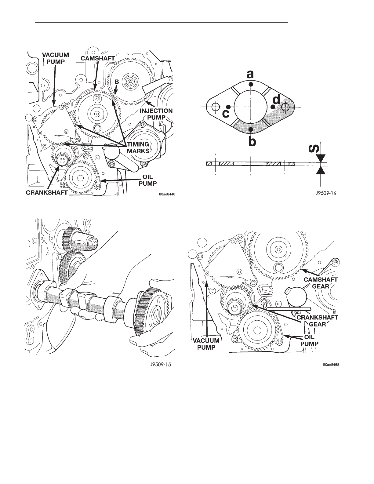
(12) Rotate the engine to align the timing marks
as shown (Fig. 42).
(13) Unscrew the flange bolts and remove camshaft (Fig. 43).
THRUST PLATE INSPECTION
Check the thickness (Fig. 44) of the plate at points
a-b-c-d. If the measurement is not between 3.950 -
4.050 it must be changed.
INSTALLATION
(1) Coat the camshaft journals with clean engine
oil and carefully install the camshaft complete with
Page 31
XJ ENGINE 9 - 31
REMOVAL AND INSTALLATION (Continued)
Fig. 42 Timing Marks
Fig. 43 Camshaft Removal
thrust plate and gear. Tighten retaining bolts to 24
N·m (18 ft. lbs.) torque. Be sure to align the timing
marks as shown (Fig. 45).
(2) Install the hydraulic tappets and retainers.
Refer to hydraulic tappet removal and installation in
this section.
(3) Install the cylinder heads. Refer to cylinder
head removal and installation in this section.
(4) Install the push rods and rocker arm assemblies. Refer to the respective sections.
Fig. 44 Camshaft Thrust Plate
Fig. 45 Timing Marks
(5) Install the cylinder head cover. Refer to cylinder head cover removal and installation in this section.
(6) Install the timing gear cover. Refer to timing
gear cover removal and installation in this section.
(7) Install the vibration damper. Refer to the
vibration damper removal and installation in this
section.
(8) Install the A/C condenser. Refer to Group 24,
Heating and Air Conditioning for procedure.
Page 32
9 - 32 ENGINE XJ
REMOVAL AND INSTALLATION (Continued)
(9) Install the radiator. Refer to Group 7, Cooling
System for procedure.
(10) Install the fan and fan shroud,. Torque fan to
56 N·m (41 ft. lbs.).
(11) If equipped, evacuate and charge the air conditioning system. Refer to Group 24, Heater and Air
Conditioning for procedure.
(12) Connect the negative battery cable.
(13) Fill the cooling system. Check for leaks.
WARNING: USE EXTREME CAUTION WHEN THE
ENGINE IS OPERATING. DO NOT STAND IN DIRECT
LINE WITH THE FAN. DO NOT PUT HANDS NEAR
THE PULLEYS, BELTS OR FAN. DO NOT WEAR
LOOSE CLOTHING.
(14) Operate the engine with the radiator cap off.
Inspect for leaks and continue operating the engine
until the thermostat opens. Add coolant, if required.
CAMSHAFT BEARINGS
This procedure requires that the engine is removed
from the vehicle.
REMOVAL
(1) With the engine completely disassembled,
remove camshaft rear plate and o-ring.
(2) Install the proper size adapters and horseshoe
washers (part of Camshaft Bearing Remover/Installer
Tool C-3132–A) at back of each bearing shell. Drive
out the bearing shells.
INSTALLATION
(1) Install the new camshaft bearings with Camshaft Bearing Remover/Installer Tool C3131–A by
sliding the new camshaft bearing shell over proper
adapter.
(2) Position the rear bearing in the tool. Install
horseshoe lock and by reversing removal procedure,
carefully drive bearing shell into place.
(3) Install the remaining bearings in the same
manner. The Bearings must be carefully aligned to
bring oil holes into full register with oil passages
from the main bearing. If the camshaft bearing shell
oil holes are not in exact alignment, remove and
install them correctly. Install a new rear plate o-ring
at the rear of camshaft. Be sure this seal does not
leak.
OIL PAN
REMOVAL
(1) Disconnect the negative battery cable.
(2) Raise the vehicle on hoist.
(3) Drain the oil.
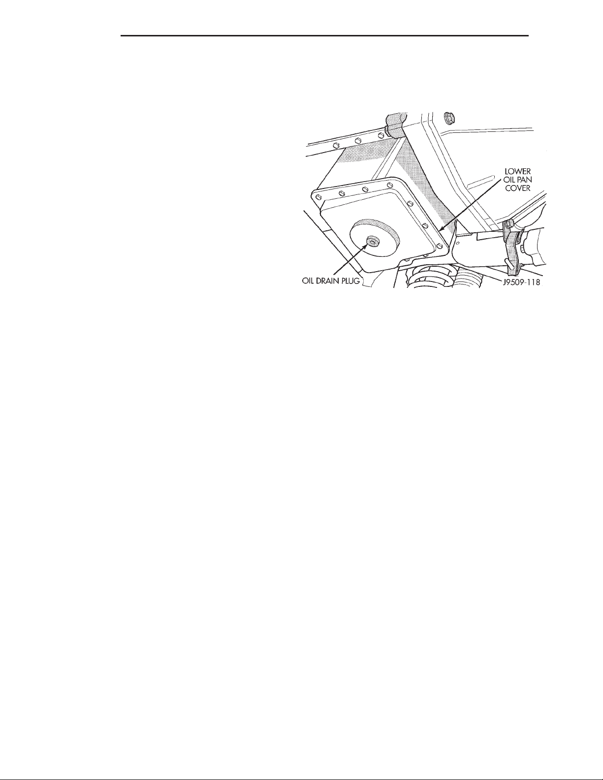
(4) Remove the oil pan lower cover (Fig. 46).
(5) Remove the bolts from oil pan. Remove the 6
bolts that are on the inside of the oil pan.
(6) Remove the oil pan.
Fig. 46 Oil Pan
INSTALLATION
(1) Remove all gasket material from cylinder block.
Be careful not gouge or scratch aluminum pan sealing surface.
(2) Apply a continuous 3 mm bead of Silicone
Sealer to oil pan, install within 10 minutes. Install
the oil pan.
(3) Install the inside oil pan bolts. Torque bolts to
11 N·m (8 ft. lbs.).
(4) Torque the smaller oil pan bolts to 11 N·m (8 ft.
lbs.). Torque the larger oil pan bolts to 25 N·m (18 ft.
lbs.).
(5) Install the oil drain plug. Torque to 79 N·m (58
ft. lbs).
(6) Lower the vehicle from hoist.
(7) Fill engine with proper amount of oil.
(8) Connect the negative battery cable.
OIL PUMP
REMOVAL
(1) Disconnect the negative battery cable.
(2) Remove the timing gear cover. Refer to timing
gear cover removal and installation in this section).
(3) Remove the oil pump (Fig. 47).
INSTALLATION
(1) Install new O-ring and lubricate with clean
engine oil.
(2) Install the oil pump. Torque screws to 24.5-29.9
N·m (22.7-28.3 ft. lbs.). Check for normal backlash
between pump and crankshaft gears.
(3) Install the timing gear cover. Refer to timing
gear cover removal and installation in this section.
Page 33
XJ ENGINE 9 - 33
REMOVAL AND INSTALLATION (Continued)
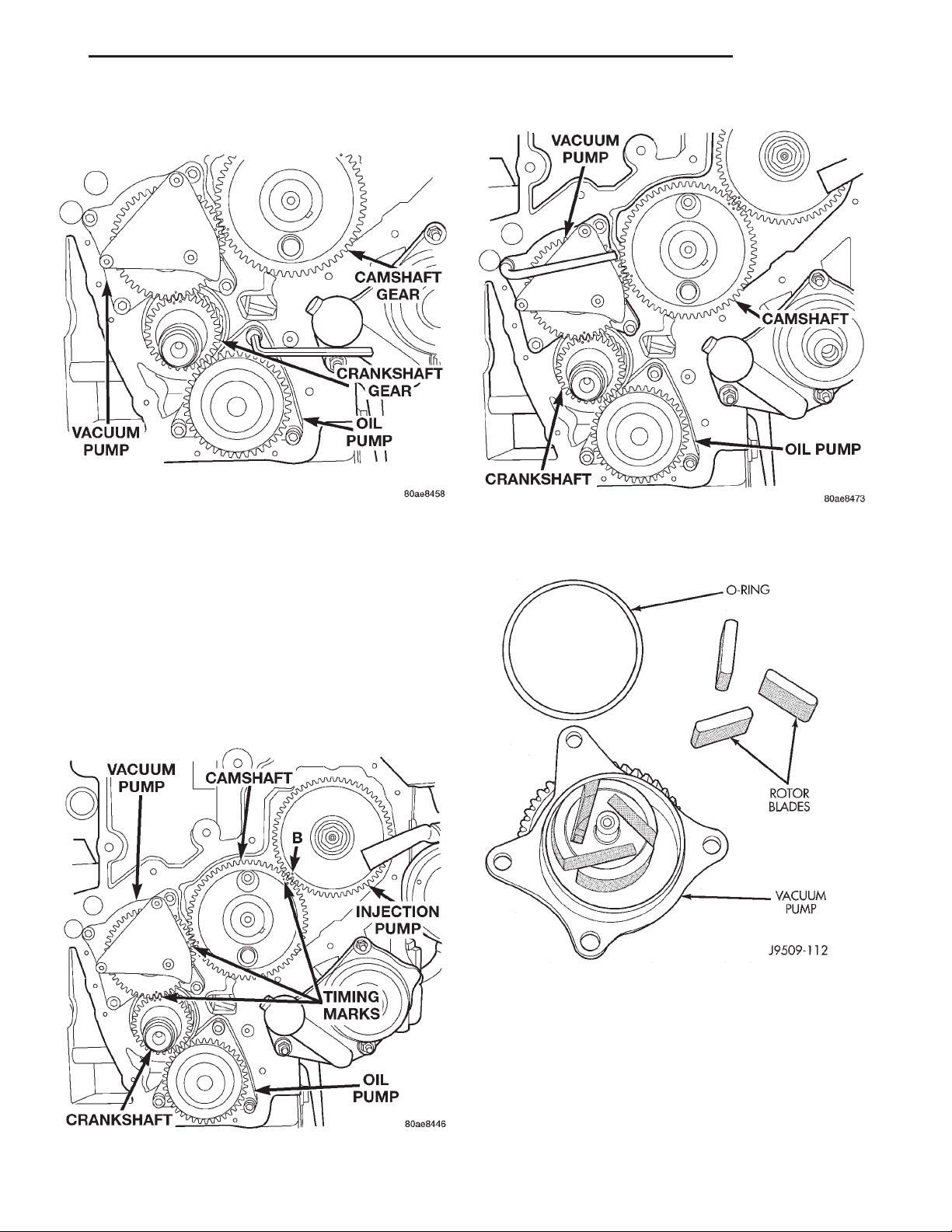
Fig. 47 Oil Pump Removal
INTERNAL VACUUM PUMP
REMOVAL
(1) Disconnect the negative battery cable.
(2) Remove the timing gear cover. Refer to timing
gear cover removal in this section.
(3) Align all the timing marks before removing the
vacuum pump (Fig. 48).
(4) Remove the vacuum pump retaining bolts..
Fig. 49 Vacuum Pump
(5) Remove the internal vacuum pump.
Fig. 50 Vacuum Pump Parts
Fig. 48 Timing Marks
INSTALLATION
(1) To install the vacuum pump, align the outer
part of the gear with the inner part using a screwdriver or similar tool, align with timing marks on
gear set and install (Fig. 48). Torque bolts to 20 N·m
(15 ft. lbs.).
(2) Install the timing gear cover. Refer to timing
gear cover removal in this section.
(3) Connect the negative battery cable.
Page 34
9 - 34 ENGINE XJ
REMOVAL AND INSTALLATION (Continued)
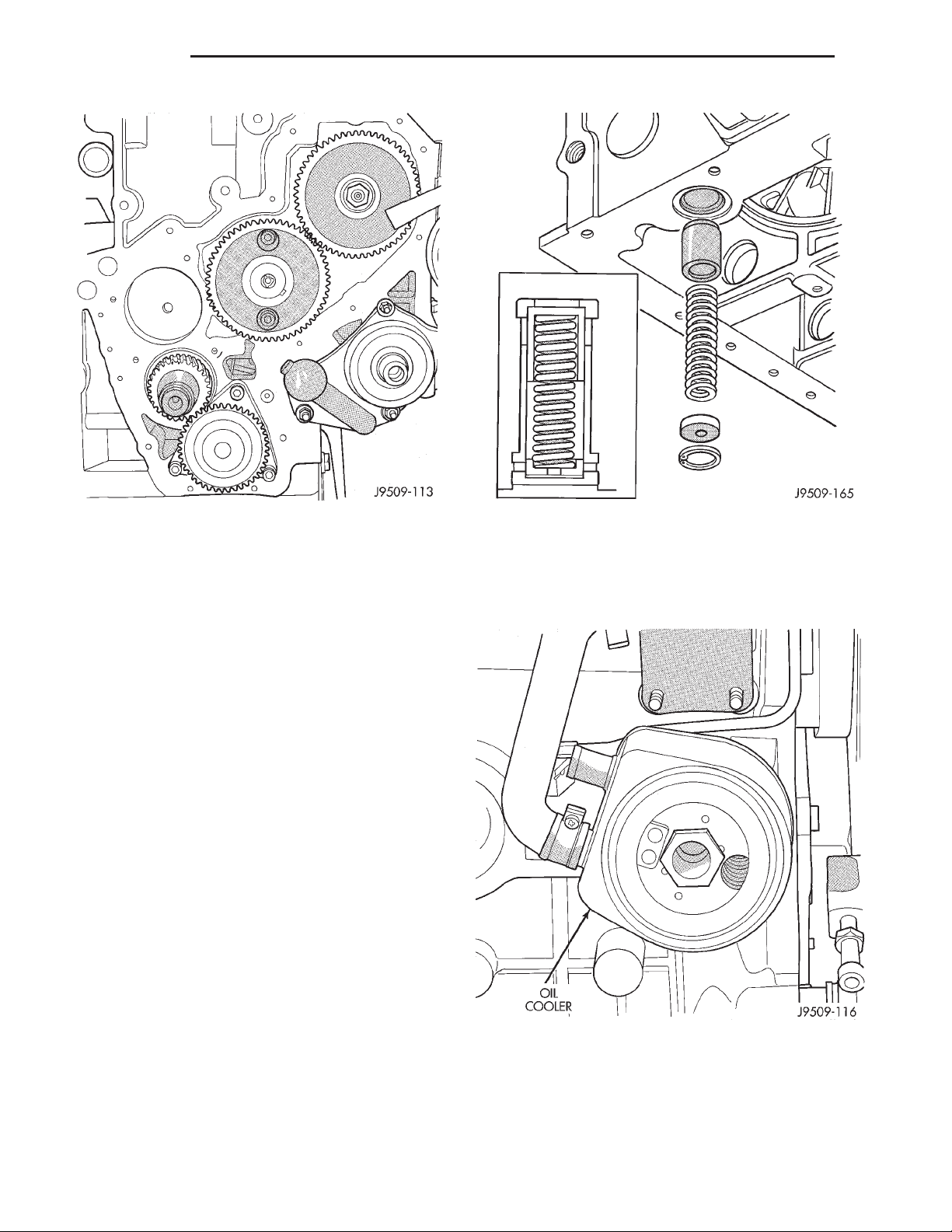
Fig. 51 Vacuum Pump Mounting Hole
OIL PUMP PRESSURE RELIEF VALVE
REMOVAL
(1) Disconnect the negative battery cable
(2) Remove the oil pan. Refer to oil pan removal
and installation procedure in this section.
(3) Remove the relief valve snap ring.
(4) Remove the relief valve cap, spring, and
plunger (Fig. 52).
(5) Check the relief valve spring length. Relief
valve spring free length is 57.5mm (2.263 in.). If
spring length is less or spring is distorted it must be
replaced.
(6) Check the plunger for scoring, replace if necessary.
INSTALLATION
(1) Thoroughly clean all components and relief
valve pocket in cylinder block.
(2) Fit plunger, spring and cap into block.
(3) Compress spring and install the snap ring.
Ensure the snap ring is completely seated in groove.
(4) Install the oil pan. Refer to oil pan removal
and installation procedure in this section.
(5) Connect the negative battery cable.
Fig. 52 Oil Pressure Relief Valve
(4) Remove the oil filter base, allen bolt in center
of adapter.
(5) Remove the oil cooler adapter bolt.
(6) Remove the oil cooler (Fig. 53).
OIL FILTER ADAPTER
REMOVAL
(1) Disconnect the negative battery cable.
(2) Remove the oil filter.
(3) Remove the oil filter adapter.
Fig. 53 Oil Cooler
INSTALLATION
(1) Install the oil cooler with new gasket. Torque
the oil cooler adapter bolt to 60 N·m (44 ft. lbs.).
(2) Install the oil filter base with new o-ring.
Torque bolt to 46.6 N·m (34 ft. lbs.).
Page 35
XJ ENGINE 9 - 35
REMOVAL AND INSTALLATION (Continued)
(3) Install the oil filter adapter to oil filter base.
Torque to 46.6 N·m (34 ft. lbs.).
(4) Install the oil filter. Torque to 18 N·m (13 ft.
lbs.) and add oil.
(5) Connect the negative battery cable.
PISTONS AND CONNECTING ROD ASSEMBLY
REMOVAL
(1) Disconnect the battery cable.
(2) Remove cylinder heads, refer to cylinder head
removal in this section.
(3) Raise vehicle on host.
(4) Remove oil pan, refer to oil pan removal in this
section.
(5) Remove top ridge of cylinder bores with a reliable ridge reamer before removing pistons from cylinder block. Be sure to keep tops of pistons
covered during this operation. Mark piston with
matching cylinder number.
(6) Pistons and connecting rods must be removed
from top of cylinder block. Rotate crankshaft so that
each connecting rod is centered in cylinder bore.
(7) Remove connecting rod cap. Install connecting
rod bolt protectors on connecting rod bolts. Push each
piston and rod assembly out of cylinder bore.
NOTE: Be careful not to nick crankshaft journals.
(8) After removal, install bearing cap on the mating rod.
PISTON PIN—REMOVAL
(1) Secure connecting rod in a soft jawed vice.
(2) Remove 2 clips securing piston pin.
(3) Push piston pin out of piston and connecting
rod.
PISTON RING—REMOVAL
(1) ID mark on face of upper and intermediate piston rings must point toward piston crown.
(2) Using a suitable ring expander, remove upper
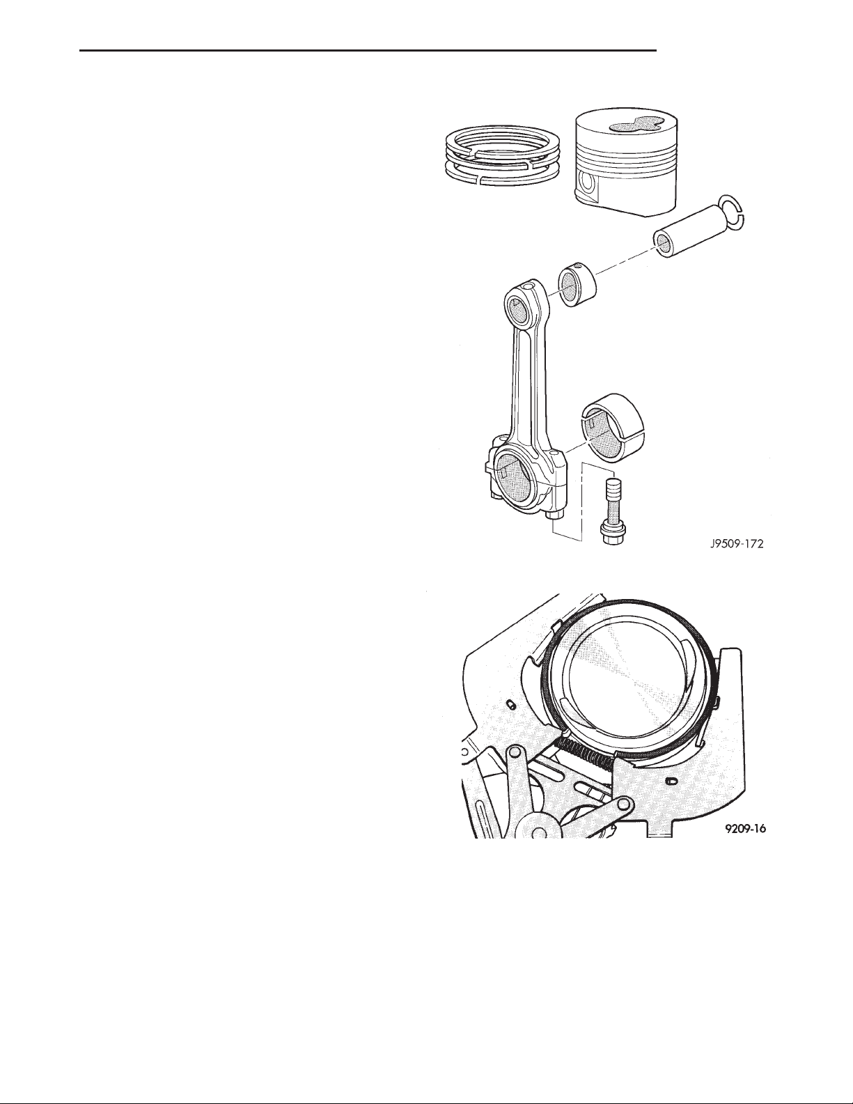
and intermediate piston rings (Fig. 55).
(3) Remove the upper oil ring side rail, lower oil
ring side rail and then oil ring expander from piston.
(4) Carefully clean carbon from piston crowns,
skirts and ring grooves ensuring the 4 oil holes in
the oil control ring groove are clear.
PISTON RING FITTING
(1) Wipe cylinder bore clean. Insert ring and push
down with piston to ensure it is square in bore. The
ring gap measurement must be made with the ring
positioning at least 12 mm (0.50 in.) from bottom of
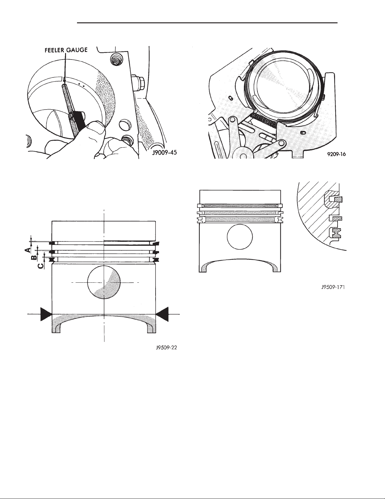
cylinder bore. Check gap with feeler gauge. Top compression ring gap .25 to .50mm (.0098 to .0196 in.).
Second compression ring gap .25 to .35mm (.0098 to
Fig. 54 Piston Assembly
Fig. 55 Piston Rings—Removing and Installing
.0137 in.). Oil control ring gap .25 to .58mm (.0098 to
.0228 in.).
(2) If ring gaps exceed dimension given, new rings
or cylinder liners must be fitted. Keep piston rings in
piston sets.
(3) Check piston ring to groove clearance (Fig. 57).
Top compression ring gap .08 to .130mm (.0031 to
.0051 in.). Second compression ring gap .070 to
Page 36
9 - 36 ENGINE XJ
REMOVAL AND INSTALLATION (Continued)
Fig. 56 Ring Gap Measurement
.102mm (.0027 to .0040 in.). Oil control ring gap .040
to .072mm (.0015 to .0028 in.).
Fig. 57 Piston Ring to Groove Clearance
PISTON RINGS—INSTALLATION
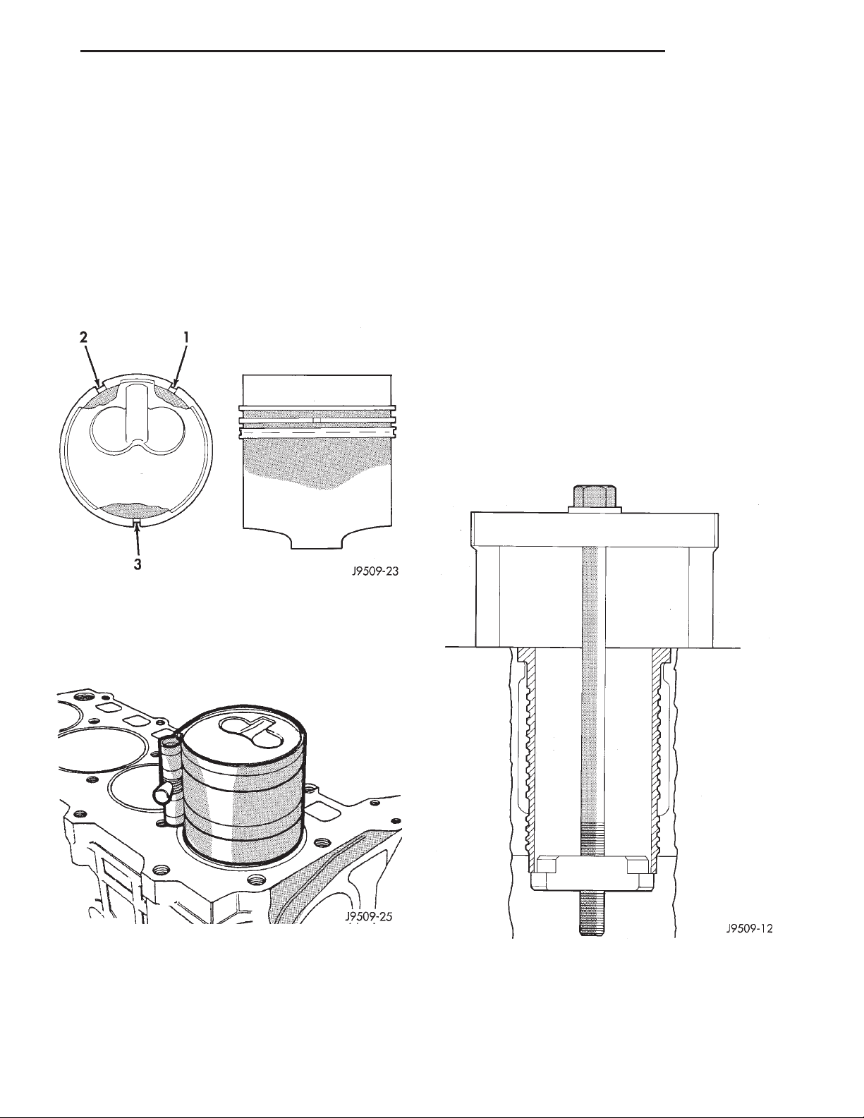
(1) Install rings on the pistons using a suitable
ring expander (Fig. 58).
(2) Top compression ring is tapered and chromium
plated. The second ring is of the scraper type and
must be installed with scraping edge facing bottom of
the piston. The third is an oil control ring. Ring gaps
must be positioned, before inserting piston into the
liners, as follows (Fig. 60).
(3) Top ring gap must be positioned at 30 degrees
to the right of the combustion chamber recess (looking at the piston crown from above).
Fig. 58 Piston Rings—Removing and Installing
Fig. 59 Piston Ring Identification
(4) Second piston ring gap should be positioned on
the opposite side of the combustion chamber recess.
(5) Oil control ring gap to be located 30 degrees to
the left of combustion chamber recess.
(6) When assembling pistons check that components are installed in the same position as before disassembly, determined by the numbers stamped on
the crown of individual pistons. Engine cylinders are
numbered starting from gear train end of the engine.
Face chamber recess side of piston towards
camshaft. Therefore, the numbers stamped on con
rod big end should also face in the same direction. To
insert piston into cylinder use a ring compressor as
shown in (Fig. 58).
PISTON PIN INSTALLATION
(1) Secure connecting rod in soft jawed vice.
(2) Lubricate piston pin and piston with clean oil.
(3) Position piston on connecting rod.
Page 37
XJ ENGINE 9 - 37
REMOVAL AND INSTALLATION (Continued)
CAUTION: Ensure combustion recess in piston
crown and the bearing cap numbers on the connecting rod are on the same side.
(4) Install piston pin.
(5) Install clips in piston to retain piston pin.
(6) Remove connecting rod from vice.
INSTALLATION
(1) Before installing pistons, and connecting rod
assemblies into the bore, be sure that compression
ring gaps are staggered so that neither is in line with
oil ring rail gap (Fig. 60).
(4) Face chamber recess side of piston towards
camshaft.
(5) Install connecting rod bolt protectors on rod
bolts.
(6) Rotate crankshaft so that the connecting rod
journal is on the center of the cylinder bore. Insert
rod and piston into cylinder bore and guide rod over
the crankshaft journal.
(7) Tap the piston down in cylinder bore, using a
hammer handle. At the same time, guide connecting
rod into position on connecting rod journal.
(8) Install rod caps. Install nuts on cleaned and
oiled rod bolts and tighten nuts to 29.5 N·m (22 ft.
lb.) plus 60°.
CYLINDER WALL LINER ASSEMBLY
REMOVAL
(1) Remove cylinder heads.
(2) Remove Oil pan.
(3) Remove pistons.
(4) Use tool VM-1001 to remove liners (Fig. 62).
Fig. 60 Piston Ring Gap Location
(2) Before installing the ring compressor, make
sure the oil ring expander ends are butted and the
rail gaps located as shown in (Fig. 60).
Fig. 61 Installing Piston
(3) Immerse the piston head and rings in clean
engine oil, slide the ring compressor, over the piston
and tighten with the special wrench (Fig. 61).
Ensure position of rings does not change during this operation.
Fig. 62 Liner Removal Tool
(5) Remove shims from cylinder liner or cylinder
block recess. Keep shims with each cylinder liner.
Page 38
9 - 38 ENGINE XJ
REMOVAL AND INSTALLATION (Continued)
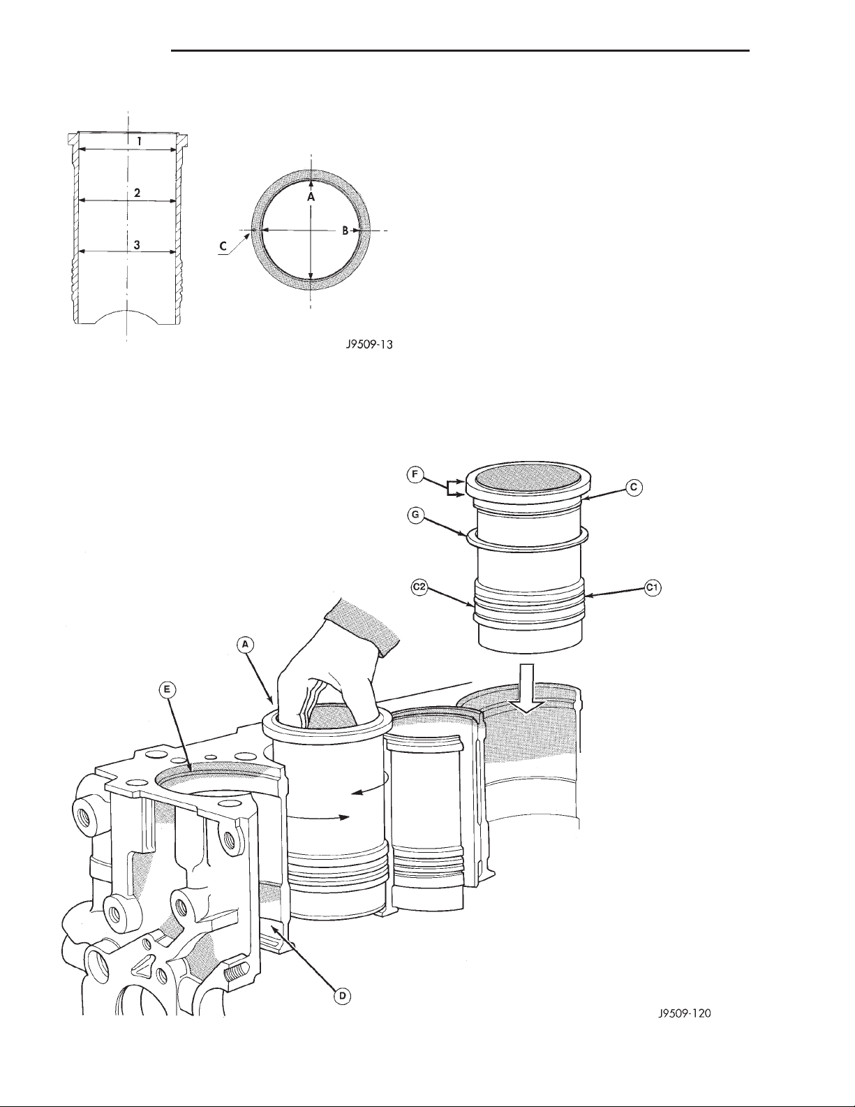
comes into contact with the liners. Install the liners
in the crankcase as shown (A), rotating them back
and forth by 45° in order to guarantee correct positioning (Fig. 64).
(2) Measure the liner recess relative to block deck
with a dial indicator mounted on a special tool
VM-1010 A. All the measurements must be taken
on camshaft side. Zero dial gauge on block deck.
(3) Move dial gauge to cylinder liner record reading on dial gauge.
(4) Remove liner and special tool.
(5) Then select the correct shim thickness to give
proper protrusion (0.01 - 0.06 mm).
(6) Fit the shim and the O-rings onto the liner.
(7) Lubricate the lower liner location in the block.
Apply LOCTITE AVX to the corner of the liner seat.
Fig. 63 Liner Inspection
INSTALLATION
(1) Carefully clean residual LOCTITE from liner
and crankcase, and degrease the crankcase where it
Apply LOCTITE AVX uniformly to the upper part of
the liner at area.
(8) Fit the liners in the crankcase making sure
that the shim is positioned correctly in the seat. Lock
Fig. 64 Liner Installation
Page 39
XJ ENGINE 9 - 39
REMOVAL AND INSTALLATION (Continued)
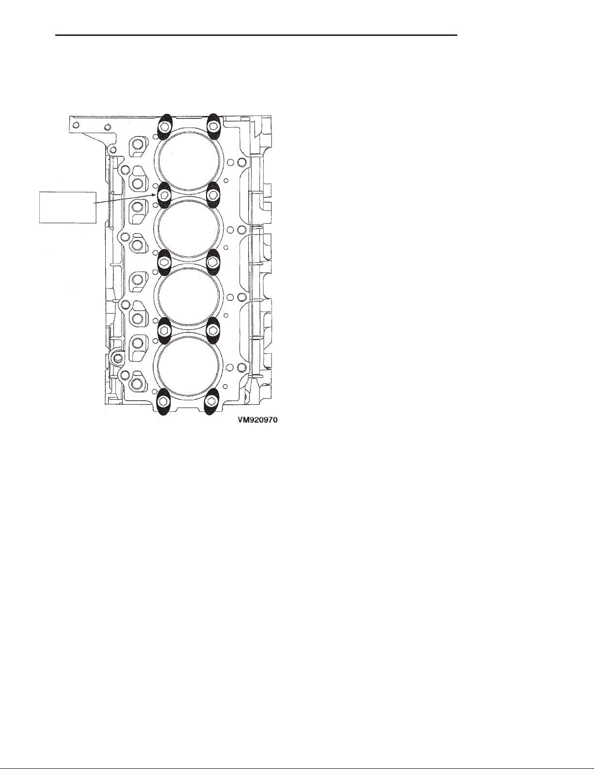
the liners in position using special tool (VM-1016)
and bolts (Fig. 65). Clean the residual LOCTITE on
the upper surface of the block deck.
Fig. 65 Liner Clamp Location
(9) Recheck the liner protrusion. It should be 0.01
- 0.06 mm.
NOTE: A period of six hours must elapse between
the liners being installed and engine start-up. If
engine assembly is not continued after liner installation, the liners need to be clamped for twelve
hours minimum.
CRANKSHAFT MAIN BEARINGS
REMOVAL
(1) Disconnect the negative battery cable.
(2) Remove the engine from vehicle. Refer to
engine removal and installation in this section.
(3) Install the engine on an engine stand.
(4) Remove the accessary drive system.
(5) Remove the cylinder head cover. Refer to cylinder head cover removal and installation in this section.
(6) Remove the rocker arm assemblies and push
rods. Refer to rocker arm and push rod removal and
installation in this section.
(7) Remove the intake manifold, exhaust manifold
and turbocharger. Refer to Group 11, Exhaust System and Turbocharger.
(8) Remove the water manifold.
(9) Remove the oil feed lines to rocker arms.
(10) Remove the cylinder heads. Refer to cylinder
head removal and installation in this section.
(11) Remove the oil pan and oil pick-up.
(12) Remove the pistons and connecting rods.
(13) Remove the vibration damper. Refer to vibration damper removal and installation in this section.
(14) Remove the timing gear cover. Refer to timing
gear cover removal and installation in this section.
(15) Remove the oil pump and vacuum pump from
block.
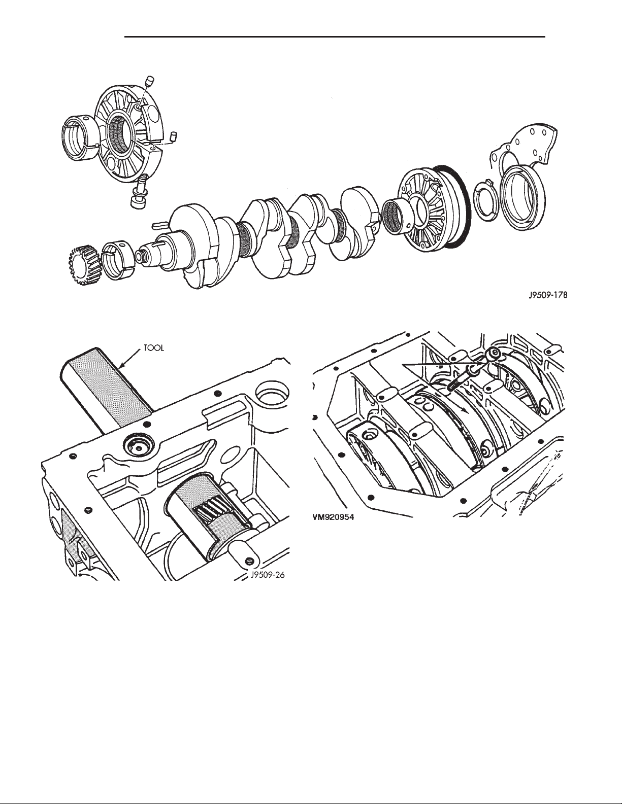
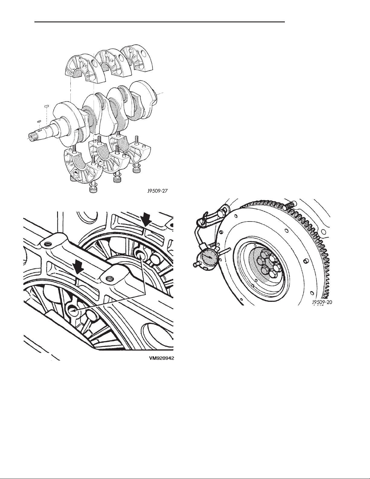
(16) Install special tool VM.1004 onto crankshaft
over gear (Fig. 67).
(17) Remove the main bearing oil feed and crankshaft support locators from block.
(18) Remove the flywheel and adaptor plate from
engine block.
(19) Remove the thrust bearings from rear main
bearing carrier.
(20) Slide the crankshaft and bearing carriers
rearward to rear of block. If you encounter difficulty
in removing the complete assembly as previously
described, slide the assembly rearward sufficiently to
gain access to the main bearing carrier bolts. Mark
the carriers for assembly and remove the bolts, two
for each carrier (Fig. 68).
(21) Separate the two halves of each carrier,
remove from the crankshaft and temporarily re-assemble the carriers (Fig. 69). Withdraw the crankshaft through the rear of the crankcase.
INSTALLATION
NOTE: Be sure the oil jets are facing the front of
the engine.
(1) Fit the main bearing supports together. Torque
to 42 N·m (31 ft. lbs.)
(2) Check internal diameter of bearings.
(3) If internal diameter of original bearing is being
checked and figures are not within specifications,
new bearings must be used.
(4) Check the crankshaft main bearing journals to
bearing clearances. Clearances of main bearings is
.03 to .088mm (.0011 to .0035 in.).
NOTE: Assemble engine according to sequence
described, thus saving time and preventing damages to engine components. Clean parts with a suitable solvent and dry them with compressed air
before assembly. Use new gaskets where applicable
and torque wrenches for correct tightening of components.
Page 40
9 - 40 ENGINE XJ
REMOVAL AND INSTALLATION (Continued)
Fig. 66 Crankshaft and Bearing Assembly
Fig. 67 Crankshaft Special Tool VM.1004
(5) Thoroughly clean crankcase and oil passages,
and blow dry with compressed air.
(6) Install new main bearing shells in each of the
carrier halves. Assemble the carriers to the crankshaft journals, ensuring that the carriers are
installed in their original locations and that the pis-
ton jet notch is towards the front of the crankshaft. Secure each carrier with the two bolts
tightening evenly to 42 N·m (31 ft. lbs.). Check that
the oil jet is in position (Fig. 69).
(7) Slide special tool VM.1004 over the crankshaft
gear and, insert the crankshaft and support assembly
Fig. 68 Crankshaft Support Locator Bolts
into the crankcase in the same manner used for
removal.
(8) Align the holes in the lower supports, with the
center of the crankcase webs (Fig. 70).
(9) Secure each support assembly to the crankcase
with the main bearing oil feed and support locators.
Torque to 54 N·m (40 ft. lbs).
(10) Install the rear main bearing support onto
crankshaft ensuring arrow on bearing support aligns
with vertical web in center of crankcase.
(11) Install the rear oil seal.
(12) Install the new O-rings in adaptor plate.
(13) Install the adaptor plate to block. Torque nuts
to 26.5 N·m (20 ft. lbs.).
(14) Install the Allen bolts through adaptor plate
to rear main bearing support. Torque to 11 N·m (97
in. lbs.).
Page 41
XJ ENGINE 9 - 41
REMOVAL AND INSTALLATION (Continued)
(18) Move crankshaft toward front of engine and
zero indicator.
(19) Move crankshaft toward the rear of engine
and record measurement.
(20) Subtract specified crankshaft end play from
figure obtained. Crankshaft end play .153 to .304mm
(.0060 to .0119 in.).
(21) Select thrust washers which will give correct
end play.
(22) Remove tools and flywheel.
(23) Lubricate thrust washer halves and fit them
into the rear main bearing carrier.
(24) Ensure that crankshaft end and flywheel mating surfaces are clean and dry. Install ‘‘O’’ ring in flywheel groove.
(25) To verify correct end play, install 2 flywheel
bolts 180° apart, and tighten bolts to 20 N·m plus 60°
(15 ft. lbs. plus 60°).
(26) Measure crankshaft end play with a dial
gauge. Crankshaft end play should not exceed .153 to
.304mm (.0060 to .0119 in.) (Fig. 71).
Fig. 69 Crankshaft and Carrier Bearing Assembly
Fig. 70 Main Bearing Support Alignment
(15) Position the flywheel and O-ring on crank-
shaft and align bolt holes.
NOTE: For purposes of checking crankshaft end
play, used flywheel bolts may be used. Final assembly requires new flywheel bolts.
(16) Install 2 flywheel bolts, 180° apart, and
tighten bolts to 20 N·m plus 60° (15 ft. lbs.) plus 60°.
(17) Attach dial indicator to engine block.
Fig. 71 Measuring Crankshaft End Play
CAUTION: Use NEW flywheel bolts for the following
procedure.
(27) Install a new O-ring on flywheel. Install flywheel on crankshaft. The 6 flywheel bolts must be
tightened as follows:
a. Lubricate and install the 6 new flywheel bolts.
b. Torque the 6 flywheel bolts to 49 N·m (36 ft.
lbs.) starting one bolt and following with the opposite
one (cross tightening) until completion, in a clockwise
direction..
c. Loosen one bolt at a time and tighten to 19.6
N·m (14 ft. lbs.) plus 75° using the cross tightening
method.
(28) Install the pistons and connecting rod assemblies. Refer to piston and connecting rods removal
and installation in this section.
Page 42
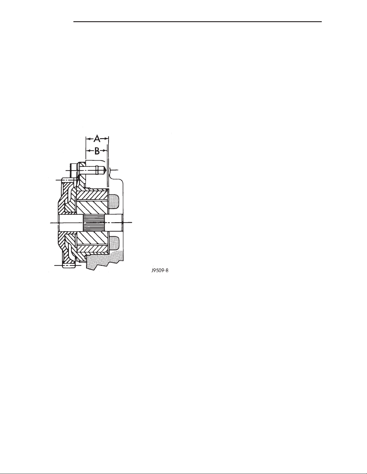
9 - 42 ENGINE XJ
REMOVAL AND INSTALLATION (Continued)
(29) Install the oil pick up tube. Torque bolts to 25
N·m (18 ft. lbs.).
(30) Install the oil pan. Refer to oil pan removal
and installation in this section.
(31) Install the vacuum pump, being careful to
align the gear timing marks with those on the crankshaft gear. Torque screws to 20 N·m (15 ft. lbs.).
(32) Before installing the oil pump check pump
bore depth in block (A) and pump body height (B)
(Fig. 72). Difference between A and B should be
0.020-0.082 mm (.0007 to 0032 in.).
DISASSEMBLY AND ASSEMBLY
HYDRAULIC TAPPETS
DISASSEMBLE
(1) Pry out plunger retainer spring clip.
(2) Clean varnish deposits from inside of tappet
body above plunger cap.
(3) Invert tappet body and remove plunger cap,
plunger, check valve, check valve spring, check valve
retainer and plunger spring. Check valve could be
flat or ball.
ASSEMBLE
(1) Clean all tappet parts in a solvent that will
remove all varnish and carbon.
(2) Replace tappets that are unfit for further service with new assemblies.
(3) If plunger shows signs of scoring or wear,
install a new tappet assembly. If valve is pitted, or
valve seat on end of plunger is prevented from seating, install a new tappet assembly.
(4) Assemble tappets.
Fig. 72 Oil Pump Bore Depth
(33) Install the oil pump. Torque screws to 27 N·M
(20 ft. lbs.). Check for normal backlash between
pump and crankshaft gears.
(34) Install the timing gear cover. Refer to timing
gear cover removal and installation in this section.
(35) Install the vibration damper. Refer to vibration damper removal and installation in this section.
(36) Install the cylinder heads. Refer to cylinder
head removal and installation in this section.
(37) Install the rocker arms and push rods. Refer
to rocker arm and push rod removal and installation
in this section.
(38) Install the cylinder head cover. Refer to cylinder head cover removal and installation in this section.
(39) Install the accessary drive system.
(40) Install the engine in vehicle. Refer to engine
removal and installation in this section.
(41) Fill engine with the correct amount of fluids
specified.
(42) Connect the negative battery cable.
CLEANING AND INSPECTION
CYLINDER HEAD
CLEANING
Thoroughly clean the engine cylinder head and cylinder block mating surfaces. Clean the intake and
exhaust manifold and engine cylinder head mating
surfaces. Remove all gasket material and carbon.
Check to ensure that no coolant or foreign material
has fallen into the tappet bore area.
Remove the carbon deposits from the combustion
chambers and top of the pistons.
INSPECTION
Use a straightedge and feeler gauge to check the
flatness of the engine cylinder head and block mating
surfaces (Fig. 73).
Minimum cylinder head thickness 89.95mm (3.541
in.)
CAUTION: If only one cylinder head is found to be
distorted and requires machining, it will also be
necessary to machine the remaining cylinders
heads and end plates by a corresponding amount
to maintain correct cylinder alignment.
Page 43
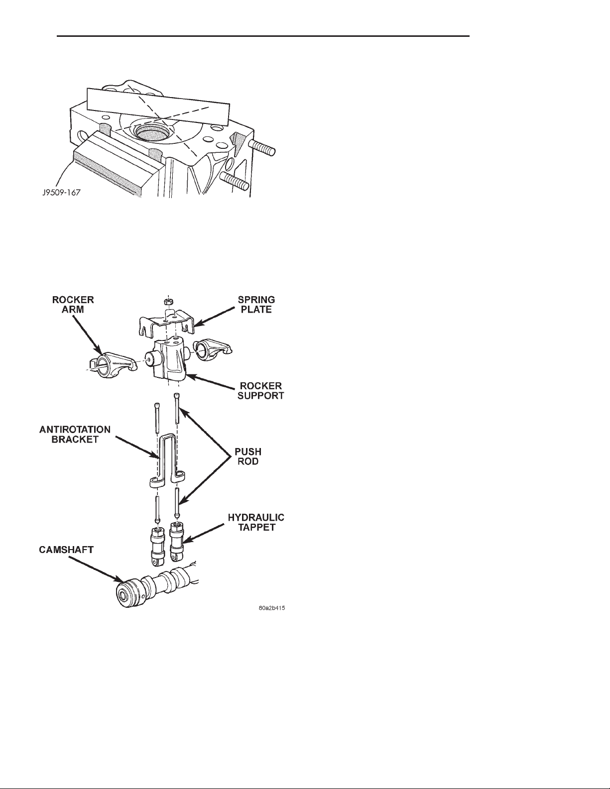
XJ ENGINE 9 - 43
CLEANING AND INSPECTION (Continued)
Inspect the valve stem tip contact surface of each
rocker arm and replace any rocker arm that is deeply
pitted.
Inspect each push rod end for excessive wear and
replace as required. If any push rod is excessively
worn because of lack of oil, replace it and inspect the
corresponding hydraulic tappet for excessive wear.
Inspect the push rods for straightness by rolling
them on a flat surface or by shining a light between
the push rod and the flat surface.
A wear pattern along the length of the push rod is
Fig. 73 Checking Cylinder Head Flatness
not normal. Inspect the engine cylinder head for
obstruction if this condition exists.
ROCKER ARMS AND PUSH RODS
PISTONS AND CONNECTING ROD ASSEMBLY
CLEANING
Clean all the components (Fig. 74) with cleaning
solvent.
INSPECTION—PISTONS
(1) Piston Diameter: Size Group A: 91.93-91.94mm
(3.6191-3.6196 in.) Size Group B: 91.94-91.95mm
(3.6196-3.6200 in.). Maximum wear limit .05mm
(.0019 in.).
(2) Check piston pin bores in piston for roundness.
Make 3 checks at 120° intervals. Maximum out of
roundness .05mm (.0019 in.).
(3) The piston diameter should be measured
approximately 15 mm (.590 in.) up from the base.
(4) Skirt wear should not exceed 0.1 mm (.00039
in.).
(5) The clearance between the cylinder liner and
piston should not exceed 0.25 mm (.0009 in.).
(6) Make sure the weight of the pistons does not
differ by more than 5 g.
Fig. 74 Rocker Arm Components
Use compressed air to blow out the oil passages in
the rocker arms and push rods.
INSPECTION
Inspect the pivot surface area of each rocker arm.
Replace any that are scuffed, pitted, cracked or
excessively worn.
INSPECTION—CONNECTING ROD
(1) Assemble bearing shells and bearing caps to
their respective connecting rods ensuring that the
serrations on the cap and reference marks are
aligned.
(2) Tighten bearing cap bolts to 29N·m (21 ft. lbs.)
plus 60°.
(3) Check and record internal diameter of crank
end of connecting rod.
NOTE: When changing connecting rods, all four
must have the same weight and be stamped with
the same number. Replacement connecting rods
will only be supplied in sets of four.
Connecting rods are supplied in sets of four since
they all must be of the same weight category. Max
allowable weight difference is 18 gr.
Page 44
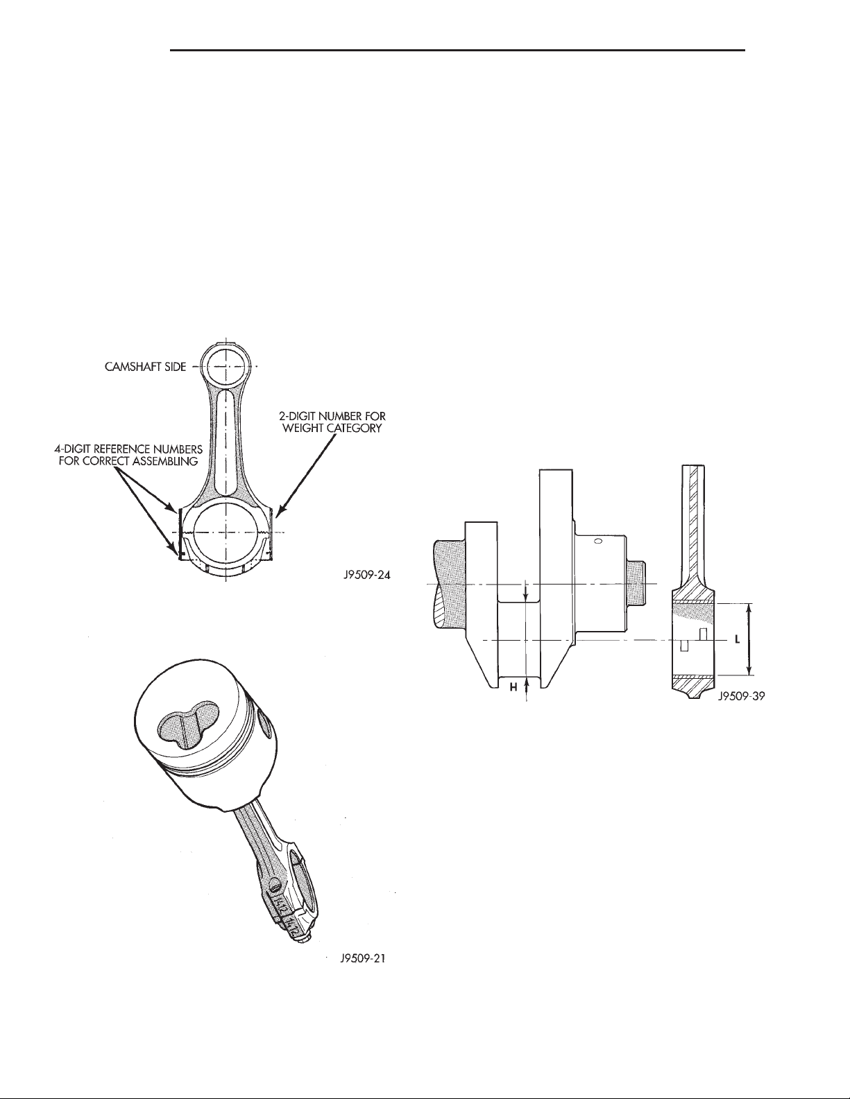
9 - 44 ENGINE XJ
CLEANING AND INSPECTION (Continued)
NOTE: On one side of the big end of the con-rod
there is a two-digit number which refers to the
weight category. On the other side of the big end
there is a four digit number on both the rod and the
cap. These numbers must both face the camshaft
as well as the recess on the piston crown (Fig. 76).
Lightly heat the piston in oven. Insert piston pin in
position and secure it with provided snap rings.
The Four digit numbers marked on con rod
big end and rod cap must be on the same side
as the camshaft (Fig. 76). After having coated
threads with Molyguard, tighten con rod bolts to 29
N·m (21 ft. lbs.) plus 60°.
INSPECTION—PISTON PIN
(1) Measure the diameter of piston pin in the center and both ends.
(2) Piston pin diameter is 29.990 to 29.996mm
(1.1807 to 1.1809 in.).
INSPECTION—CRANKSHAFT JOURNALS
(1) Using a micrometer, measure and record crankshaft connecting rod journals, take reading of each
journal 120° apart. Crankshaft journal diameter is
53.84 to 53.955mm (2.1196 to 2.1242 in.).
(2) Crankshaft journals worn beyond limits or
show signs of out of roundness must be reground or
replaced. Minimum reground diameter is 53.69mm
(2.1137 in.).
BEARING-TO-JOURNAL CLEARANCE
Compare internal diameters of connecting rod with
crankshaft journal diameter. Maximum clearance
between connecting rod and crankshaft journals .022
to .076mm (.0008 to .0029 in.).
Fig. 75 Connecting Rod Identification
Fig. 76 Piston and Connecting Rod Assembly
Fig. 77 Bearing Clearance
CYLINDER WALL LINER ASSEMBLY
INSPECTION
The cylinder walls should be checked for out-ofround and taper with dail bore gauge. The cylinder
bore out-of-round is 0.100 mm (.0039 inch) maximum
and cylinder bore taper is 0.100 mm (0.0039 inch)
maximum. If the cylinder walls are badly scuffed or
scored, new liners should be installed and honed, and
new pistons and rings fitted.
Measure the cylinder bore at three levels in directions A and B (Fig. 78). Top measurement should be
10 mm ( 3/8 inch) down and bottom measurement
should be 10 mm ( 3/8 inch.) up from bottom of bore.
Page 45
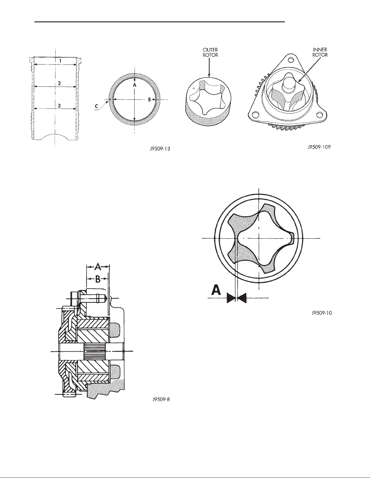
XJ ENGINE 9 - 45
CLEANING AND INSPECTION (Continued)
Fig. 78 Liner Inspection
OIL PUMP
CLEANING
Wash all parts in a suitable solvent and inspect
carefully for damage or wear.
INSPECTION
(1) Before installing oil pump check pump bore
depth in block (A) and pump body height (B) (Fig.
79). Difference between A and B should be
0.020-0.082 mm.
Fig. 80 Oil Pump Inner and Outer Rotors
Fig. 81 Checking Rotor Clearance
Fig. 79 Oil Pump Bore Depth
(2) Check clearance between rotors (Fig. 81).
Page 46
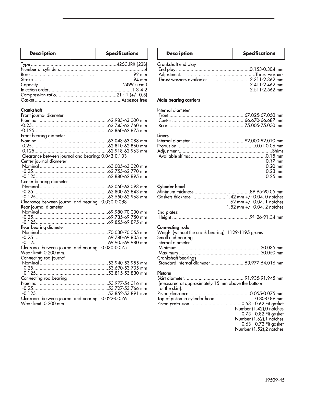
9 - 46 ENGINE XJ
SPECIFICATIONS
ENGINE SPECIFICATIONS
Page 47
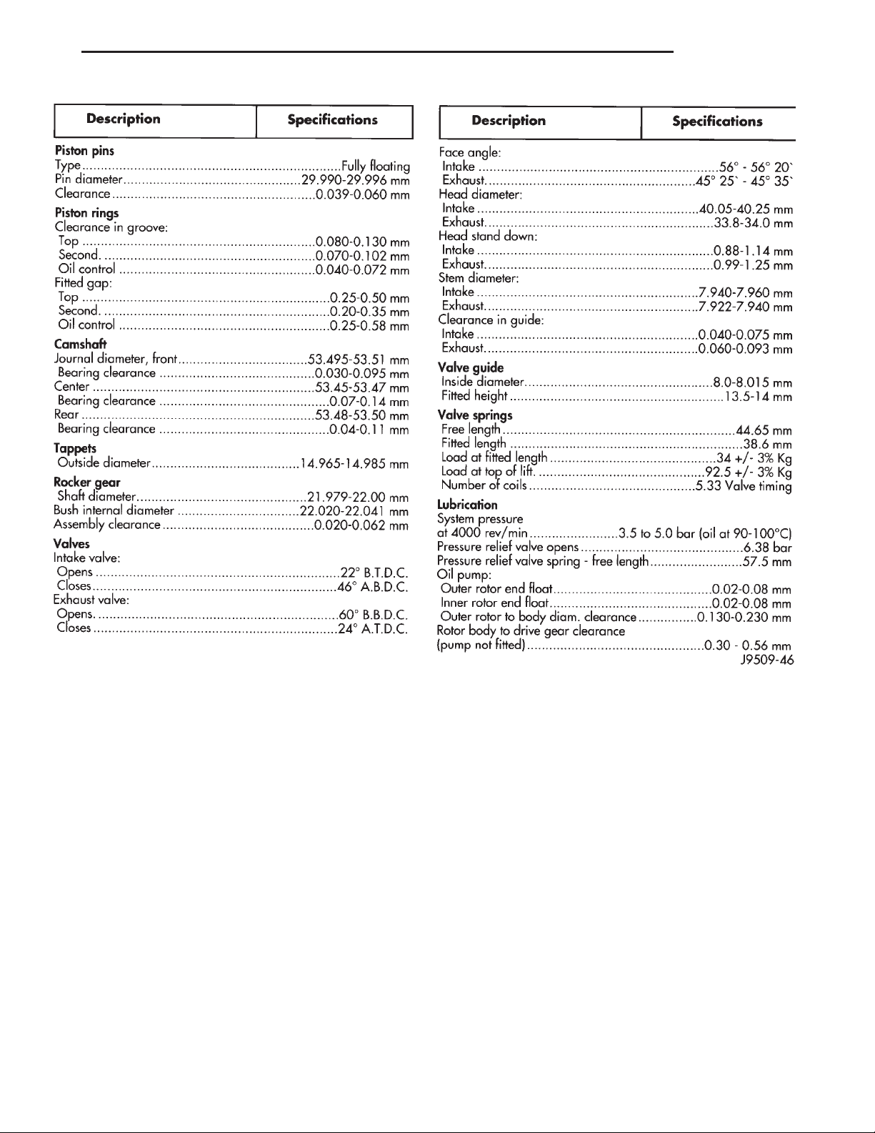
XJ ENGINE 9 - 47
SPECIFICATIONS (Continued)
Page 48

9 - 48 ENGINE XJ
SPECIFICATIONS (Continued)
TORQUE SPECIFICATIONS
DESCRIPTION TORQUE
Adaptor Plate to Block
Nuts (6) .................26.5 N·m ( 20 ft. lbs.)
Automatic Belt Tensioner to Block
Bolts (2) ...........................121N·m
Automatic Belt Tensioner to Mounting Bracket
Bolt (1) .............................75N·m
Generator belt
Tensioner ...........................79N·m
Generator bracket
Mounting bolts (6 mm) .................10N·m
Mounting bolts (8 mm) ...............24.4 N·m
Generator
Mounting bolt ........................47N·m
Camshaft thrust plate
Bolts ...............................24N·m
Connecting rod
Mounting bolt ..................29.5 N·m +60°
Crankshaft bearing
Carrier screw ........................42N·m
Crankshaft pulley
Locknut ...........................160N·m
Crossmember
Bolts ...............................42N·m
Diesel delivery
Union nut .........................18.5 N·m
EGR valve
To intake manifold ....................26N·m
EGR tube
To EGR valve ........................26N·m
Engine mount—Front
Engine support bracket ................61N·m
Support Cushion .....................47N·m
Support cushion bracket bolts ...........54N·m
Support cushion bracket stud nuts ........41N·m
Support Cushion through bolt ...........65N·m
Engine mount—Rear
Transmission support bracket ...........46N·m
Support Cushion nuts .................75N·m
Support Cushion through bolt ...........65N·m
Exhaust down pipe
To turbocharger ......................22N·m
Exhaust heat shield
Screws .............................11N·m
Exhaust manifold collar
Mounting nut .................24.5 to 29.5 N·m
Exhaust manifold
Mounting nut ......................32.5 N·m
Fan drive
Tofanhub ..........................56N·m
Flywheel
Lock bolt .......................20N·m+60°
DESCRIPTION TORQUE
Front timing cover
6 mm bolts ..........................10N·m
8 mm bolts ..........................26N·m
Fuel filter
Nuts ...............................28N·m
Glow plug
Torque ............................13.0 N·m
Idler pulley bracket
Bolts ...............................40N·m
Idler pulley
Bolt (left hand thread) .................47N·m
Injection pump fuel lines
Nut................................23N·m
Injection pump gear
Lock nut ............................86N·m
Injection pump
Mounting nut ......................27.5 N·m
Injector
Torque ............................68.5 N·m
Intake manifold
Mounting nut ......................32.5 N·m
Main bearing oil delivery
Union ..............................54N·m
Water hose to cylinder head
Nut ............................8to10N·m
Oil cooler adaptor
Bolt ...............................60N·m
Oil feed line
For rocker arms ......................12N·m
To block ............................27N·m
To vacuum pump .....................15N·m
Oil filter
Torque .............................18N·m
Oil filter adapter
Torque ............................46.6 N·m
Oil filter base
Torque ............................46.6 N·m
Oil pan
Mounting bolts .......................13N·m
Oil pickup tube
Torque .............................25N·m
Oil pump
Mounting screw ......................27N·m
Oil sump drain plug
Torque .............................54N·m
Power steering pressure hose
Nut................................28N·m
Power steering pulley
Nut...............................130N·m
Rear crankshaft bearing carrier Allen Bolts
Torque .............................11N·m
Rocker cover
Bolts ...............................19N·m
Page 49
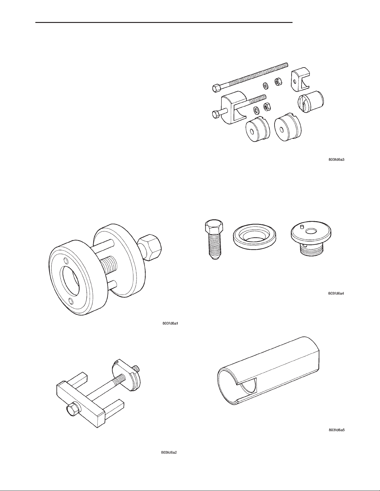
XJ ENGINE 9 - 49
SPECIFICATIONS (Continued)
DESCRIPTION TORQUE
Rocker mounting
Lock Nut ...........................35N·m
Steering pump
Bolts ...............................28N·m
Turbocharger
Mounting nuts ......................32.5 N·m
Turbocharger
Oil delivery fitting ...................27.5 N·m
Turbocharger oil drain
Plug ..............................10.8 N·m
Vacuum pump
Torque .............................27N·m
Water manifold
Bolts ...............................12N·m
Water pump pulley
Nut................................27N·m
Crankshaft Bearing Remover/Replacer VM. 1002
SPECIAL TOOLS
SPECIAL TOOLS
Crankshaft Pulley and Gear Remover VM. 1000A
Injection Pump Puller and Gear retainer VM. 1003
Cylinder Liner Puller VM, 1001
Crankshaft Remover/Replacer Sleeve VM. 1004
Page 50
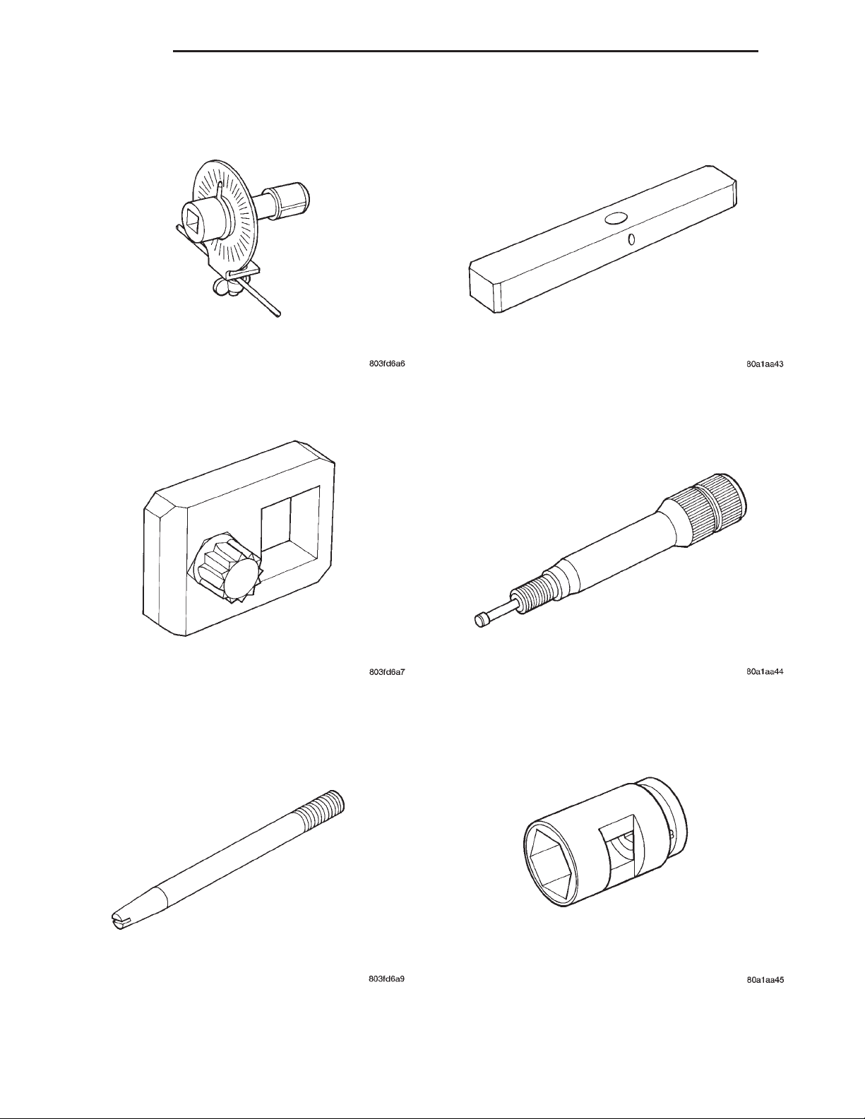
9 - 50 ENGINE XJ
SPECIAL TOOLS (Continued)
Torque Angle Gauge VM. 1005
Cylinder Head Bolt Wrench VM. 1006A
Cylinder Liner Protrusion Tool VM. 1010
Bosch Pump Timing Adapter VM. 1011
Cylinder Head Guide Studs VM. 1009
Injector Remover/Replacer Socket VM. 1012
Page 51
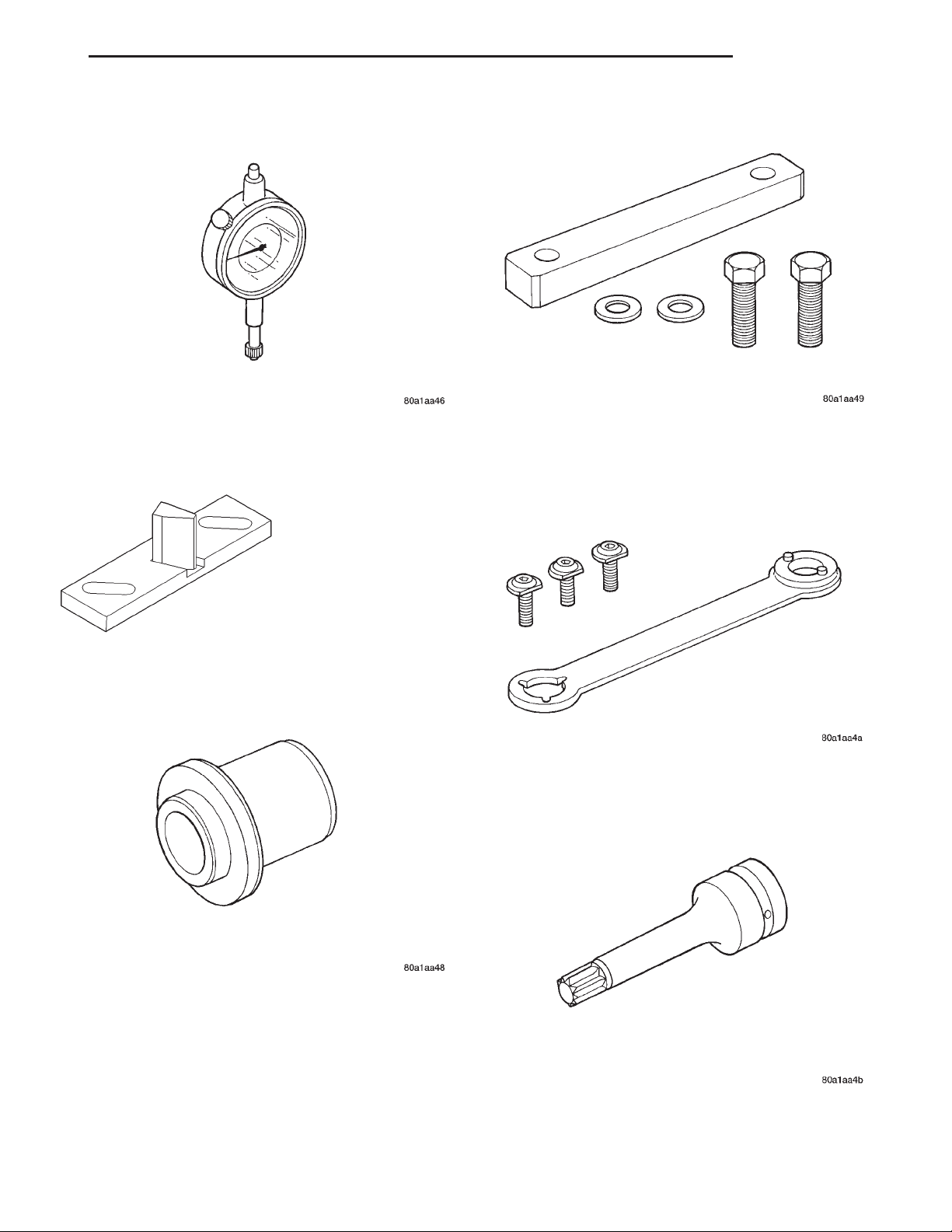
XJ ENGINE 9 - 51
SPECIAL TOOLS (Continued)
Dial Indicator Gauge VM. 1013
Flywheel Locking Tool VM. 1014
Cylinder Retainer VM. 1016
Crankshaft and Water Pump Pulley Holder VM. 1017
Timing Cover Oil Seal Replacer VM. 1015
Cylinder Head Bolt Wrench M12 VM. 1018
Page 52
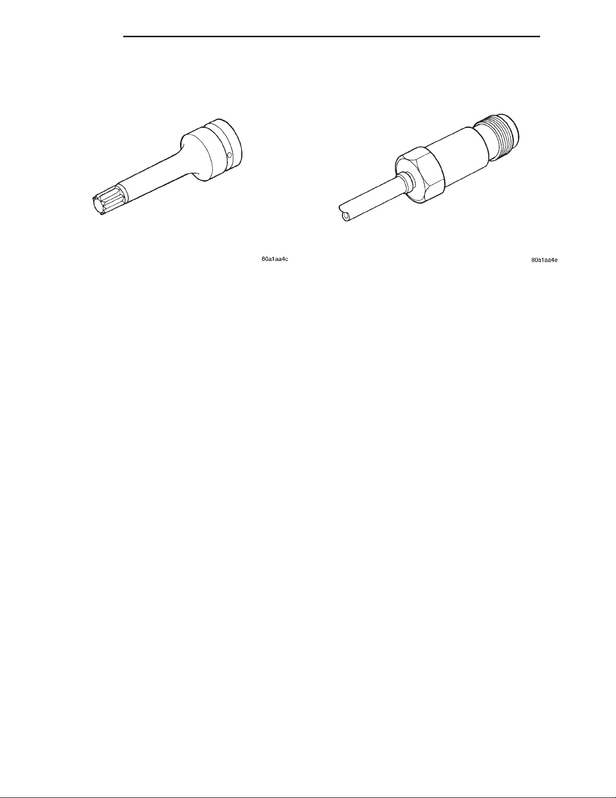
9 - 52 ENGINE XJ
SPECIAL TOOLS (Continued)
Cylinder Head Bolt Wrench M14 VM. 1019 Cylinder Leakage Tester Adapter VM. 1021
 Loading...