

Page 1
XJ POWER WINDOW SYSTEMS 8S - 1
POWER WINDOW SYSTEMS
TABLE OF CONTENTS
page page
GENERAL INFORMATION
INTRODUCTION ..........................1
POWER WINDOW SYSTEM.................1
DESCRIPTION AND OPERATION
POWER WINDOW SWITCH .................1
DOOR MODULE ..........................2
POWER WINDOW MOTOR..................2
CIRCUIT BREAKER........................2
DIAGNOSIS AND TESTING
POWER WINDOW SYSTEM.................2
GENERAL INFORMATION
INTRODUCTION
Power windows are available as factory-installed
optional equipment on this model. The power lock
system and power mirror system are included on
vehicles equipped with the power window option.
Refer to 8W-60 - Power Windows in Group 8W - Wiring Diagrams for complete circuit descriptions and
diagrams.
NOTE: This group covers both Left-Hand Drive
(LHD) and Right-Hand Drive (RHD) versions of this
model. Whenever required and feasible, the RHD
versions of affected vehicle components have been
constructed as mirror-image of the LHD versions.
While most of the illustrations used in this group
represent only the LHD version, the diagnostic and
service procedures outlined can generally be
applied to either version. Exceptions to this rule
have been clearly identified as LHD or RHD, if a
special illustration or procedure is required.
POWER WINDOW SYSTEM
The power window system allows all of the door
windows to be raised and lowered electrically by
actuating a switch on the trim panel of each respective door. Additionally, a set of master switches on
the driver side front door trim panel allows the
driver to raise or lower each of the passenger door
windows. A power window lockout switch on the
driver side front door trim panel can prevent the passenger door windows from being operated, except
from the master switches. The power window system
receives battery current through a circuit breaker in
CIRCUIT BREAKER........................3
DOOR MODULE ..........................3
POWER WINDOW SWITCH .................4
POWER WINDOW MOTOR..................4
REMOVAL AND INSTALLATION
DOOR MODULE ..........................4
POWER WINDOW SWITCH .................5
POWER WINDOW MOTOR..................6
the junction block, only when the ignition switch is
in the On or Accessory positions.
The power window system includes the power window switches on each door trim panel, the circuit
breaker in the junction block, and the power window
motors inside each door. This group covers diagnosis
and service of only the electrical components in the
power window system. For service of mechanical
components, such as the regulator, lift plate, window
tracks, or glass refer to Group 23 - Body.
Following are general descriptions of the major
components in the power window system. Refer to
the owner’s manual in the vehicle glove box for more
information on the features, use and operation of the
power window system.
DESCRIPTION AND OPERATION
POWER WINDOW SWITCH
The individual power windows are controlled by a
two-way momentary switch mounted on the trim
panel of the passenger side front door trim panel
and, on four-door models, on each of the rear door
trim panels. Two-way momentary master switches on
the driver side front door trim panel control all of the
power windows in the vehicle. The driver side front
door trim panel also has a two-position power window lockout switch.
The front door power window switches and the
power window lockout switch are integral to the
Driver Door Module (DDM) or Passenger Door Module (PDM), respectively. The rear door power window
switches are stand-alone units.
Each power window switch controls its power window motor by switching battery current and ground
Page 2

8S - 2 POWER WINDOW SYSTEMS XJ
DESCRIPTION AND OPERATION (Continued)
between the terminals of the power window motor.
The passenger side front door and, on four-door models, both rear door power window switches receive
their battery feed through the power window lockout
switch or through the master switches in the DDM.
Also, each of the individual power window switches
receives its ground through the DDM. When the lockout switch is placed in the Lock position, the individual power window switches become inoperative
because they have no battery current available to
them. However, the master switches are unaffected
by the lockout switch position.
Each power window switch, except the lockout
switch, is illuminated by a Light-Emitting Diode
(LED) when the ignition switch is turned to the On
position. However, when the power window lockout
switch is placed in the Lock position, the LED for the
locked-out passenger side front and, on four-door
models, the rear passenger door power window
switches is turned off.
The front door power window switches and their
lamps cannot be repaired and, if faulty or damaged,
the entire door module must be replaced. The rear
door power window switches and their lamps cannot
be repaired but, if faulty or damaged, only the
affected switch unit must be replaced.
DOOR MODULE
A Driver Door Module (DDM) and a Passenger
Door Module (PDM) are used on all models equipped
with power locks and power windows. Each door
module houses both the front door power lock and
power window switches. In addition to the switches
for its own door, the DDM houses individual switches
for each passenger door power window, a power window lockout switch, the power mirror switch, and circuitry to support the one-touch down feature of the
driver side front door power window. The PDM also
houses the control circuitry and the power lock and
unlock relays for the power lock system.
The DDM and the PDM are mounted to their
respective front door trim panels. The DDM and
PDM are serviced individually and cannot be
repaired. If the DDM or PDM, or any of the switches
and circuitry that they contain are faulty or damaged, the complete DDM or PDM unit must be
replaced.
POWER WINDOW MOTOR
A permanent magnet reversible motor moves the
window regulator through an integral gearbox mechanism. A positive and negative battery connection to
the two motor terminals will cause the motor to
rotate in one direction. Reversing the current
through these same two connections will cause the
motor to rotate in the opposite direction.
In addition, each power window motor is equipped
with an integral self-resetting circuit breaker to protect the motor from overloads. The power window
motor and gearbox assembly cannot be repaired and,
if faulty or damaged, the entire power window regulator assembly must be replaced.
CIRCUIT BREAKER
An automatic resetting circuit breaker in the junction block is used to protect the power window system circuit. The circuit breaker can protect the
system from a short circuit, or from an overload condition caused by an obstructed or stuck window glass
or regulator.
The circuit breaker cannot be repaired and, if
faulty, it must be replaced.
DIAGNOSIS AND TESTING
POWER WINDOW SYSTEM
For circuit descriptions and diagrams, refer to
8W-60 - Power Windows in Group 8W - Wiring Diagrams.
ALL WINDOWS INOPERATIVE
(1) Check the circuit breaker in the junction block,
as described in this group. If OK, go to Step 2. If not
OK, replace the faulty circuit breaker.
(2) Disconnect and isolate the battery negative
cable. Remove the driver side front door trim panel
and unplug the Driver Door Module (DDM) wire harness connectors from the DDM. Check for continuity
between the ground circuit cavity of the 8-way DDM
wire harness connector and a good ground. If OK, go
to Step 3. If not OK, repair the circuit to ground as
required.
(3) Connect the battery negative cable. Turn the
ignition switch to the On position. Check for battery
voltage at the master switch power feed (run/acc) circuit cavity of the 12-way DDM wire harness connector. If OK, see the diagnosis for the Door Module in
this group. If not OK, repair the open circuit to the
circuit breaker in the junction block as required.
ONE WINDOW INOPERATIVE
The window glass must be free to slide up and
down for the power window motor to function properly. If the glass is not free to move up and down, the
motor will overload and trip the integral circuit
breaker. To determine if the glass is free, disconnect
the regulator plate from the glass. Then slide the
window up and down by hand.
There is an alternate method to check if the glass
is free. Position the glass between the up and down
stops. Then, shake the glass in the door. Check that
Page 3
XJ POWER WINDOW SYSTEMS 8S - 3
DIAGNOSIS AND TESTING (Continued)
the glass can be moved slightly from side to side,
front to rear, and up and down. Then check that the
glass is not bound tight in the tracks. If the glass is
free, proceed with the diagnosis that follows. If the
glass is not free, refer to Group 23 - Body for the
door window glass and hardware service and adjustment procedures.
(1) Check the power window switch continuity as
described in the diagnosis for the Door Module (front
doors) or Power Window Switch (rear doors) in this
group. If OK and the driver side front window is
inoperative, see the Power Window Motor diagnosis
in this group. If OK and the inoperative window is
other than the driver side front, go to Step 2. If not
OK, replace the faulty door module or switch.
(2) Refer to the circuit diagrams in 8W-60 - Power
Windows in Group 8W - Wiring Diagrams. Check the
continuity in each circuit between the inoperative
Passenger Door Module (PDM) or power window
switch wire harness connector cavities and the corresponding Driver Door Module (DDM) wire harness
connector cavities. If OK, see the diagnosis for the
Power Window Motor in this group. If not OK, repair
the open circuit(s) as required.
NOTE: All individual power window switches
receive their battery and ground feeds through the
Driver Door Module (DDM) and wire harness connectors.
the passenger side front door power window switch
and, on four-door models, the rear door power window switches get their battery current through the
power window lockout switch in the Driver Door
Module (DDM). In addition, each individual power
window switch gets its ground through the master
switch in the DDM.
The one-touch down feature circuitry within the
DDM will not operate the power window motor if the
door glass, window regulator, or gearbox mechanism
are stuck, obstructed, or binding. If the driver side
front door power window operates as designed, but
the one-touch down feature is inoperative, replace
the faulty DDM.
If the problem being diagnosed is an inoperative
power window switch illumination lamp, but the
power window switch operates as designed, replace
the faulty door module. For circuit descriptions and
diagrams, refer to 8W-60 - Power Windows in Group
8W - Wiring Diagrams.
(1) Disconnect and isolate the battery negative
cable. Remove the front door trim panel and unplug
the door module wire harness connectors from the
door module.
(2) Check the door module power window switch
and/or power window lockout switch continuity in
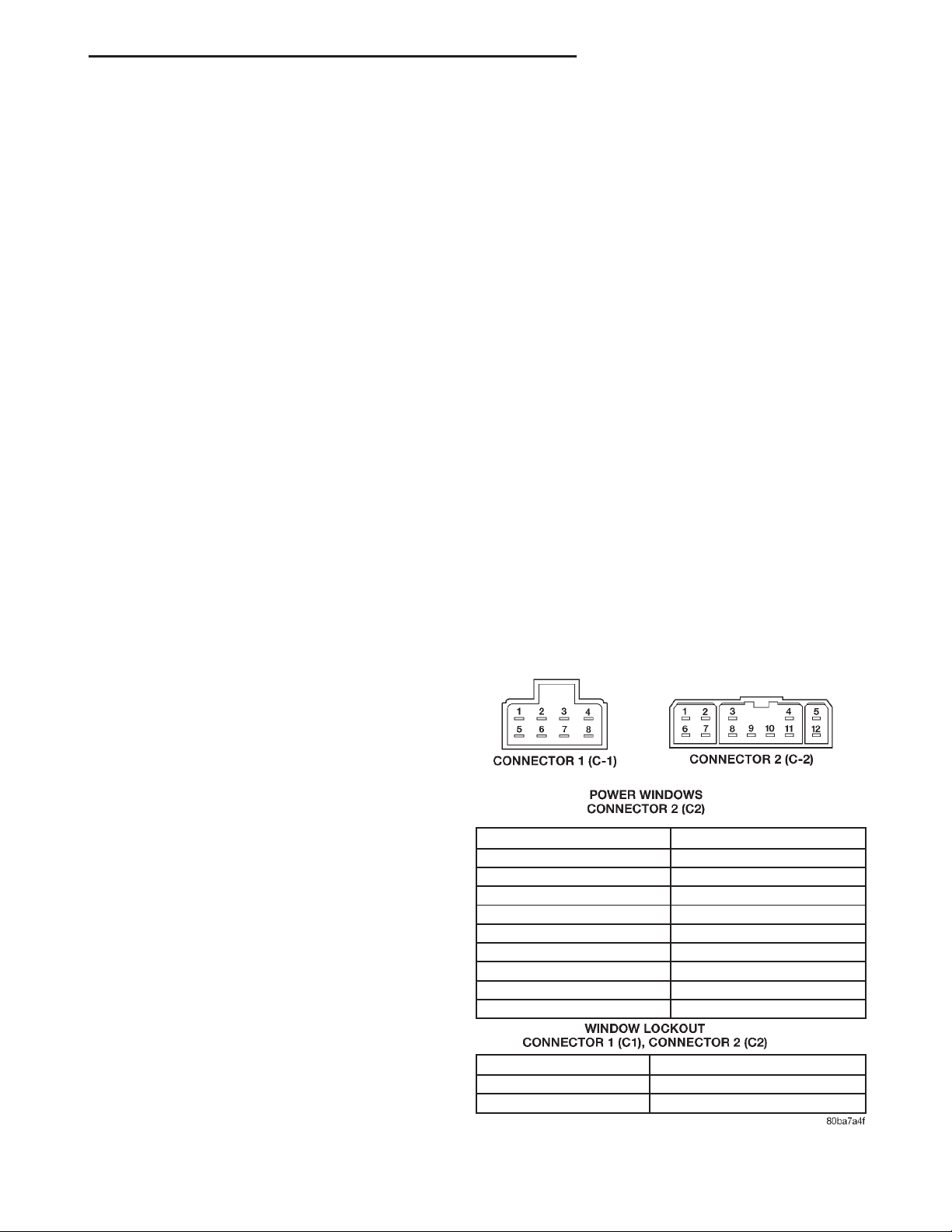
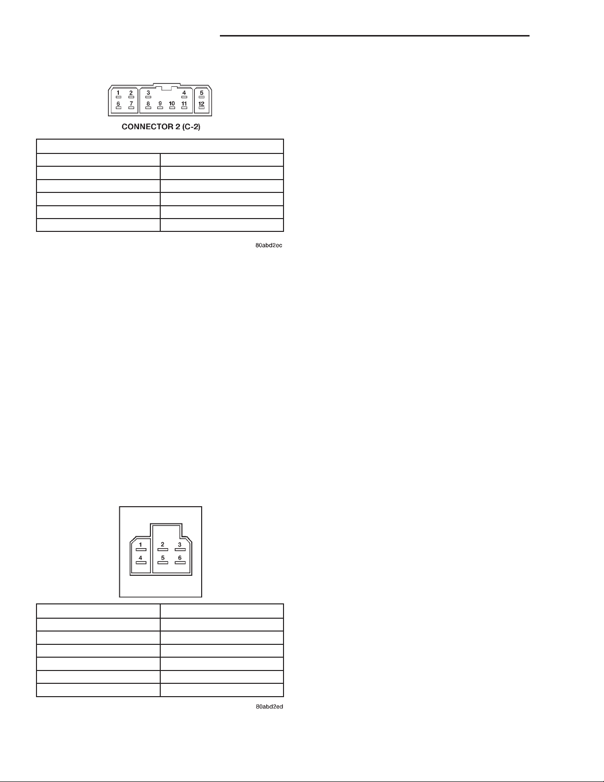
each position, as shown in the proper chart (Fig. 1)
or (Fig. 2). If OK, see the Power Window Motor diagnosis in this group. If not OK, replace the faulty door
module.
CIRCUIT BREAKER
For circuit descriptions and diagrams, refer to
8W-60 - Power Windows in Group 8W - Wiring Diagrams.
(1) Locate the circuit breaker in the junction block.
Pull out the circuit breaker slightly, but be certain
that the circuit breaker terminals still contact the
terminals in the junction block cavities.
(2) Connect the negative lead of a 12-volt DC voltmeter to a good ground.
(3) With the voltmeter positive lead, check both
terminals of the circuit breaker for battery voltage.
If only one terminal has battery voltage, the circuit
breaker is faulty and must be replaced. If neither terminal has battery voltage, repair the open circuit
from the Power Distribution Center (PDC) as
required. If the circuit breaker checks OK, but no
power windows operate, see Power Window System
in the Diagnosis and Testing section of this group.
DOOR MODULE
The Driver Door Module (DDM) contains the master switches and the lockout switch in the power window system. The DDM also contains an integrated
circuit to support the one-touch down feature of the
driver side front door power window. Remember that
SWITCH POSITION CONTINUITY BETWEEN
OFF (NORMAL) 1&8,2&8,3&8,4&8,5&8,6&8,10&8,12&8
RIGHT REAR DOWN 1&9,2&8
RIGHT REAR UP 2&9,1&8
RIGHT FRONT UP 3&9,6&8
LEFT REAR UP 4&9,10&8
LEFT FRONT UP 5&9,12&8
RIGHT FRONT DOWN 6&9,3&8
LEFT REAR DOWN 10&9,4&8
LEFT FRONT DOWN 12&9,5&8
SWITCH POSITION CONTINUITY BETWEEN
LOCKOUT OFF (UP) C1 PIN8&C2PIN9
LOCKOUT ON (DOWN) NO CONTINUITY BETWEEN C1 PIN8&C2PIN9
Fig. 1 DDM Power Window Switch Continuity
Page 4
8S - 4 POWER WINDOW SYSTEMS XJ
DIAGNOSIS AND TESTING (Continued)
POWER WINDOW MOTOR
For circuit descriptions and diagrams, refer to
8W-60 - Power Windows in Group 8W - Wiring Diagrams. Before you proceed with this diagnosis, confirm proper switch operation. See the Door Module
POWER WINDOWS
OFF (NORMAL) C2 PIN2&C2PIN3
C2PIN4&C2PIN9
UP C2PIN2&C2PIN3
C2PIN9&C2PIN10
DOWN C2 PIN2&C2PIN10
C2PIN4&C2PIN9
Fig. 2 PDM Power Window Switch Continuity
POWER WINDOW SWITCH
The diagnosis found here applies only to the rear
door power window switches. For diagnosis of the
front door power window switches, see Door Module
in this group. If the problem being diagnosed is an
inoperative power window switch illumination lamp,
but the power window switch operates as designed,
replace the faulty switch. For circuit descriptions and
diagrams, refer to 8W-60 - Power Windows in Group
8W - Wiring Diagrams.
(1) Disconnect and isolate the battery negative
cable.
(2) Remove the power window switch from the
rear door trim panel.
(3) Check the power window switch continuity in
each position as shown in the Rear Door Power Window Switch Continuity chart (Fig. 3). If OK, see the
Power Window Motor diagnosis in this group. If not
OK, replace the faulty switch.
and/or Power Window Switch diagnosis in this group.
(1) Disconnect and isolate the battery negative
cable. Remove the trim panel from the door with the
inoperative power window.
(2) Unplug the power window motor wire harness
connector. Apply 12 volts across the motor terminals
to check its operation in one direction. Reverse the
connections across the motor terminals to check the
operation in the other direction. Remember, if the
window is in the full up or full down position, the
motor will not operate in that direction by design. If
OK, repair the circuits from the power window motor
to the door module or the power window switch as
required. If not OK, replace the faulty motor.
(3) If the motor operates in both directions, check
the operation of the window glass and lift mechanism
through its complete up and down travel. There
should be no binding or sticking of the window glass
or lift mechanism through the entire travel range. If
not OK, refer to Group 23 - Body to check the window glass, tracks, and regulator for sticking, binding,
or improper adjustment.
REMOVAL AND INSTALLATION
DOOR MODULE
(1) Disconnect and isolate the battery negative
cable.
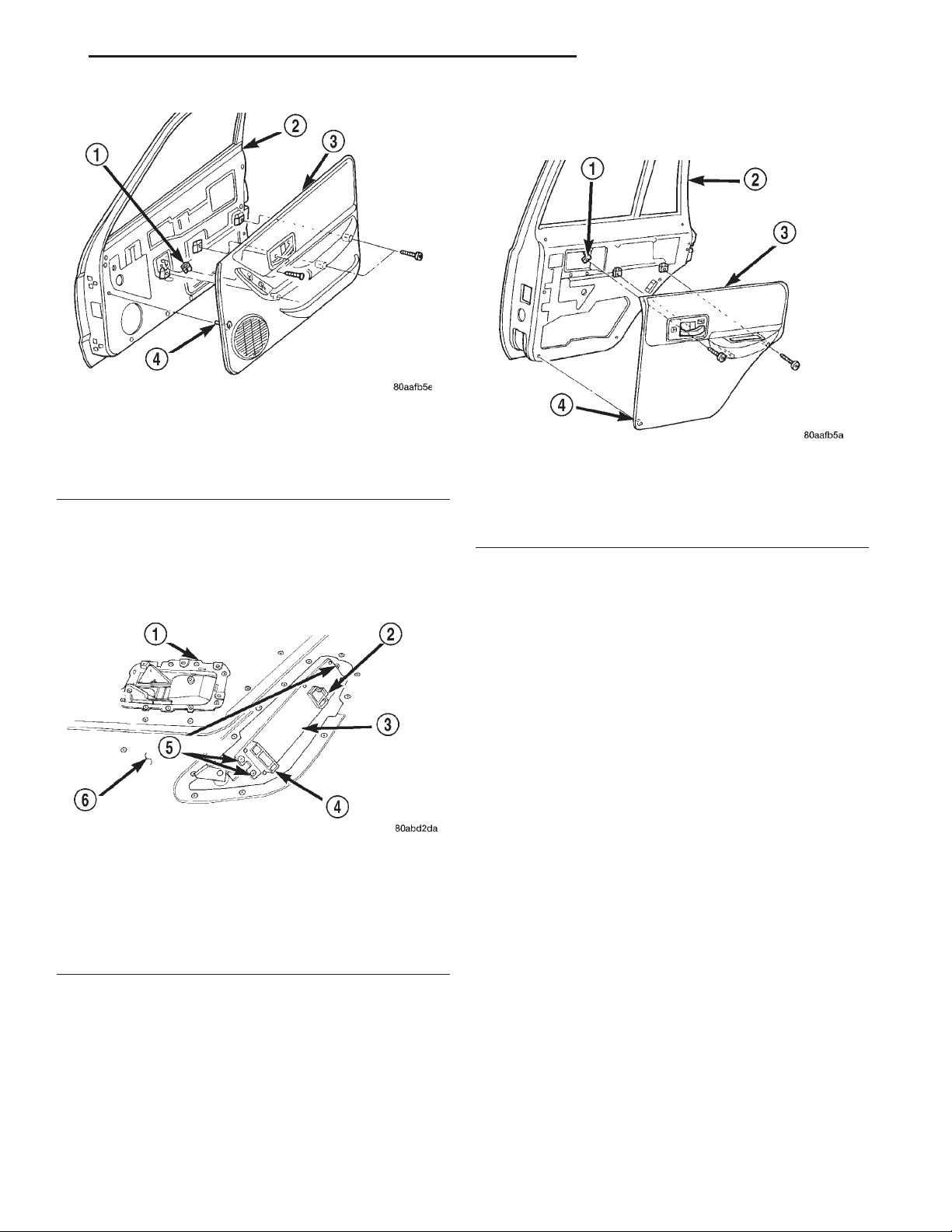
(2) Remove the screws that secure the front door
trim panel to the inner door panel (Fig. 4).
(3) Using a trim stick or another suitable wide
flat-bladed tool, gently pry the front door trim panel
away from the door around the perimeter to release
the trim panel retainers.
SWITCH POSITION CONTINUITY BETWEEN
OFF (NORMAL) 1&4
2&5
UP 1&6
2&5
DOWN 1&4
5&6
Fig. 3 Rear Door Power Window Switch Continuity
NOTE: To aid in the removal of the trim panel, start
at the bottom of the panel.
(4) Lift the front door trim panel upwards and
away from the inner door panel far enough to disengage the top of the panel from the inner belt weatherstrip.
(5) Pull the front door trim panel away from the
inner door panel far enough to access the inside door
latch release and lock linkage rods near the back of
the inside door remote controls.
(6) Unsnap the plastic retainer clips from the
inside door remote control ends of the latch release
and lock linkage rods, and remove the rod ends from
the inside door remote controls.
Page 5
XJ POWER WINDOW SYSTEMS 8S - 5
REMOVAL AND INSTALLATION (Continued)
(2) Remove the screws that secure the door trim
panel to the inner door panel (Fig. 6).
Fig. 4 Front Door Trim Panel Remove/Install
1 – U-NUT
2 – DOOR
3 – TRIM PANEL
4 – PUSH-IN FASTENER
(7) Unplug the wire harness connectors from the
door module.
(8) Remove the trim panel from the front door.
(9) Remove the three screws that secure the door
module to the front door trim panel (Fig. 5).
Fig. 6 Rear Door Trim Panel Remove/Install
1 – U-NUT
2 – REAR DOOR
3 – TRIM PANEL
4 – PUSH-IN FASTENER
(3) Using a trim stick or another suitable wide
flat-bladed tool, gently pry the rear door trim panel
away from the door around the perimeter to release
the trim panel retainers.
Fig. 5 Door Module Remove/Install
1 – INSIDE DOOR LATCH AND LOCK REMOTE CONTROLS
2 – CONNECTOR 1 RECEPTACLE
3 – DOOR MODULE
4 – CONNECTOR 2 RECEPTACLE
5 – SCREWS
6 – DOOR TRIM PANEL
(10) Remove the door module from the front door
trim panel.
(11) Reverse the removal procedures to install.
Tighten the mounting screws to 2.2 N·m (20 in. lbs.).
POWER WINDOW SWITCH
(1) Disconnect and isolate the battery negative
cable.
NOTE: To aid in the removal of the trim panel, start
at the bottom of the panel.
(4) Lift the rear door trim panel upwards and
away from the inner door panel far enough to disengage the top of the panel from the inner belt weatherstrip.
(5) Pull the rear door trim panel away from the
inner door panel far enough to access the inside door
latch release and lock linkage rods near the back of
the inside door remote controls.
(6) Unsnap the plastic retainer clips from the
inside door remote control ends of the latch release
and lock linkage rods, and remove the rod ends from
the inside door remote controls.
(7) Unplug the wire harness connector from the
rear door power window switch.
(8) Remove the trim panel from the rear door.
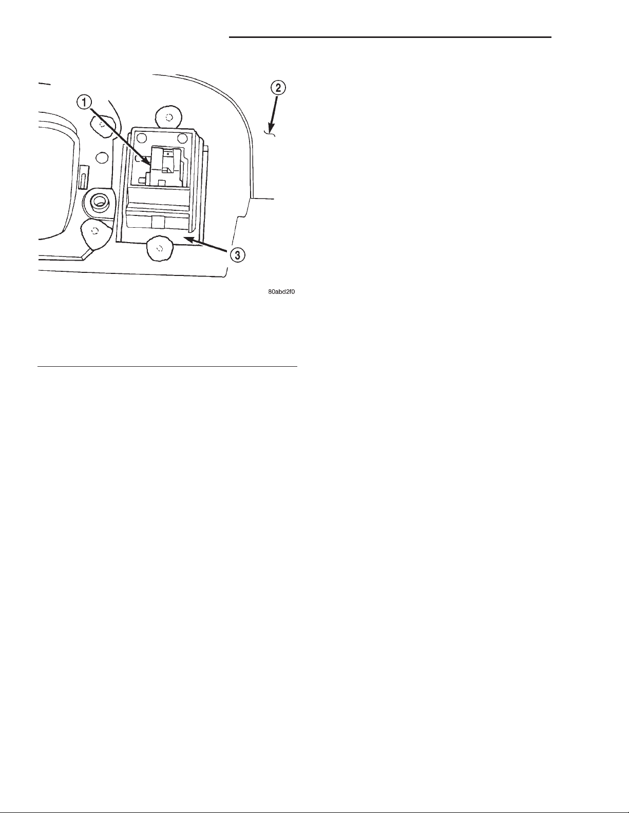
(9) With a small thin-bladed screwdriver, gently
pry the snap clips at the sides of the power window
switch receptacle on the back of the rear door trim
panel and pull the switch out of the receptacle (Fig.
7).
(10) Reverse the removal procedures to install. Be
certain that both of the switch snap retainers in the
receptacle on the back of the trim panel are fully
engaged.
Page 6
8S - 6 POWER WINDOW SYSTEMS XJ
REMOVAL AND INSTALLATION (Continued)
ulator unit. If the front door power window motor or
mechanism is faulty or damaged, the entire power
window regulator unit must be replaced. Refer to
Group 23 - Body for the front door window regulator
service procedures.
REAR DOOR
The rear door power window motor and mechanism
is integral to the rear door power window regulator
unit. If the rear door power window motor or mechanism is faulty or damaged, the entire power window
regulator unit must be replaced. Refer to Group 23 Body for the rear door window regulator service
procedures.
Fig. 7 Rear Door Power Window Switch Remove/
Install
1 – REAR DOOR POWER WINDOW SWITCH
2 – TRIM PANEL
3 – SWITCH RECEPTACLE
POWER WINDOW MOTOR
FRONT DOOR
The front door power window motor and mecha-
nism is integral to the front door power window reg-
 Loading...