

Page 1
XJ POWER SEAT SYSTEMS 8R - 1
POWER SEAT SYSTEMS
CONTENTS
page page
GENERAL INFORMATION
INTRODUCTION ......................... 1
POWER SEAT SYSTEM ................... 1
DESCRIPTION AND OPERATION
CIRCUIT BREAKER ....................... 2
POWER SEAT ADJUSTER AND MOTORS ..... 1
POWER SEAT SWITCH .................... 1
DIAGNOSIS AND TESTING
CIRCUIT BREAKER ....................... 2
GENERAL INFORMATION
INTRODUCTION
Six-way power seats are an available factory-installed option for Left-Hand Drive (LHD) versions of
this model. Refer to 8W-63 - Power Seat in Group
8W - Wiring Diagrams for complete circuit descriptions and diagrams.
NOTE: This group covers both Left-Hand Drive
(LHD) and Right-Hand Drive (RHD) versions of this
model. Whenever required and feasible, the RHD
versions of affected vehicle components have been
constructed as mirror-image of the LHD versions.
While most of the illustrations used in this group
represent only the LHD version, the diagnostic and
service procedures outlined can generally be
applied to either version. Exceptions to this rule
have been clearly identified as LHD or RHD, if a
special illustration or procedure is required.
POWER SEAT SYSTEM
The power seat system option allows the front
seating positions to be electrically adjusted for optimum control and comfort using the power seat
switches located on the outboard seat cushion side
shield. The power seat system allows the seating
position to be adjusted forward, rearward, front up,
front down, rear up, or rear down. The power seat
system receives battery current through a fuse in the
Power Distribution Center and a circuit breaker in
the junction block, regardless of the ignition switch
position.
The power seat system includes the power seat
adjuster and motors unit, the power seat switch, and
the circuit breaker. Following are general descrip-
POWER SEAT ADJUSTER AND MOTORS ..... 2
POWER SEAT SWITCH .................... 2
POWER SEAT SYSTEM ................... 2
REMOVAL AND INSTALLATION
POWER SEAT ADJUSTER AND MOTORS ..... 4
POWER SEAT SWITCH .................... 3
tions of the major components in the power seat system. Refer to the owner’s manual in the vehicle glove
box for more information on the features, use and
operation of the power seat system.
DESCRIPTION AND OPERATION
POWER SEAT SWITCH
The power seat can be adjusted in six different
ways using the power seat switch. The switch is
located on the lower outboard side of the seat cushion
on the seat cushion side shield. Refer to the owner’s
manual for more information on the power seat
switch functions and the seat adjusting procedures.
The individual switches in the power seat switch
unit cannot be repaired. If one switch is damaged or
faulty, the entire power seat switch unit must be
replaced.
POWER SEAT ADJUSTER AND MOTORS
There are three reversible motors that operate the
power seat adjuster. The motors are connected to
worm-drive gearboxes that move the seat adjuster
through a combination of screw-type drive units.
The front and rear of a seat are operated by different motors. They can be raised or lowered independently of each other. When the center seat switch is
pushed to the Up or Down position, both the front
and rear motors operate in unison, moving the entire
seat up or down. The forward-rearward motor is
operated by pushing the center seat switch to the
Forward or Rearward position.
When a switch is actuated, a battery feed and a
ground path are applied through the switch contacts
to the motor(s). The motor(s) and drives operate to
move the seat in the selected direction until the
Page 2

8R - 2 POWER SEAT SYSTEMS XJ
DESCRIPTION AND OPERATION (Continued)
switch is released, or until the travel limit of the
power seat adjuster is reached. When the switch is
moved in the opposite direction, the battery feed and
ground path to the motor(s) are reversed through the
switch contacts. This causes the motor to run in the
opposite direction.
Each motor contains a self-resetting circuit breaker
to protect it from overload. Consecutive or frequent
resetting of the circuit breakers must not be allowed
to continue, or the motors may be damaged. Make
the necessary repairs.
The power seat adjuster and motors cannot be
repaired, and are serviced only as a complete unit. If
any component in this unit is faulty or damaged, the
entire power seat adjuster and motors assembly must
be replaced.
CIRCUIT BREAKER
An automatic resetting circuit breaker in the junction block is used to protect the power seat system
circuit. The circuit breaker can protect the system
from a short circuit, or from an overload condition
caused by an obstructed or stuck seat adjuster.
The circuit breaker cannot be repaired and, if
faulty or damaged, it must be replaced.
DIAGNOSIS AND TESTING
POWER SEAT SYSTEM
Before any testing of the power seat system is
attempted, the battery should be fully-charged and
all wire harness connections and pins cleaned and
tightened to ensure proper continuity and grounds.
For circuit descriptions and diagrams, refer to
8W-63 - Power Seat in Group 8W - Wiring Diagrams.
With the dome lamp on, apply the power seat
switch in the direction of the failure. If the dome
lamp dims, the seat may be jamming. Check under
and behind the seat for binding or obstructions. If
the dome lamp does not dim, proceed with testing of
the individual components and circuits.
CIRCUIT BREAKER
For circuit descriptions and diagrams, refer to
8W-63 - Power Seat in Group 8W - Wiring Diagrams.
(1) Locate the correct circuit breaker in the junction block. Pull out the circuit breaker slightly, but
be certain that the circuit breaker terminals still contact the terminals in the junction block cavities.
(2) Connect the negative lead of a 12-volt DC voltmeter to a good ground.
(3) With the voltmeter positive lead, check both
terminals of the circuit breaker for battery voltage.
If only one terminal has battery voltage, the circuit
breaker is faulty and must be replaced. If neither ter-
minal has battery voltage, repair the open circuit
from the Power Distribution Center (PDC) as
required.
POWER SEAT ADJUSTER AND MOTORS
For circuit descriptions and diagrams, refer to
8W-63 - Power Seat in Group 8W - Wiring Diagrams.
Operate the power seat switch to move all three
seat motors in each direction. The seat should move
in each of the selected directions. If the power seat
adjuster fails to operate in only one direction, move
the adjuster a short distance in the opposite direction
and test again to be certain that the adjuster is not
at its travel limit. If the power seat adjuster still
fails to operate in only one direction, see Power Seat
Switch in the Diagnosis and Testing section of this
group. If the power seat adjuster fails to operate in
more than one direction, proceed as follows:
(1) Test the circuit breaker in the junction block as
described in this group. If OK, go to Step 2. If not
OK, replace the faulty circuit breaker.
(2) Remove the power seat switch from the seat.
Check for battery voltage at the fused B(+) circuit
cavity of the power seat switch wire harness connector. If OK, go to Step 3. If not OK, repair the open
circuit to the junction block as required.
(3) Check for continuity between the ground circuit cavity of the power seat switch wire harness connector and a good ground. There should be
continuity. If OK, go to Step 4. If not OK, repair the
open circuit to ground as required.
(4) Test the power seat switch as described in this
group. If the switch tests OK, check the wire harness
for the inoperative power seat motor(s) between the
power seat switch and the motor for shorts or opens.
If the circuits check OK, replace the faulty power
seat adjuster and motors assembly. If the circuits are
not OK, repair the wire harness as required.
POWER SEAT SWITCH
For circuit descriptions and diagrams, refer to
8W-63 - Power Seat in Group 8W - Wiring Diagrams.
(1) Disconnect and isolate the battery negative
cable.
(2) Remove the power seat switch from the power
seat.
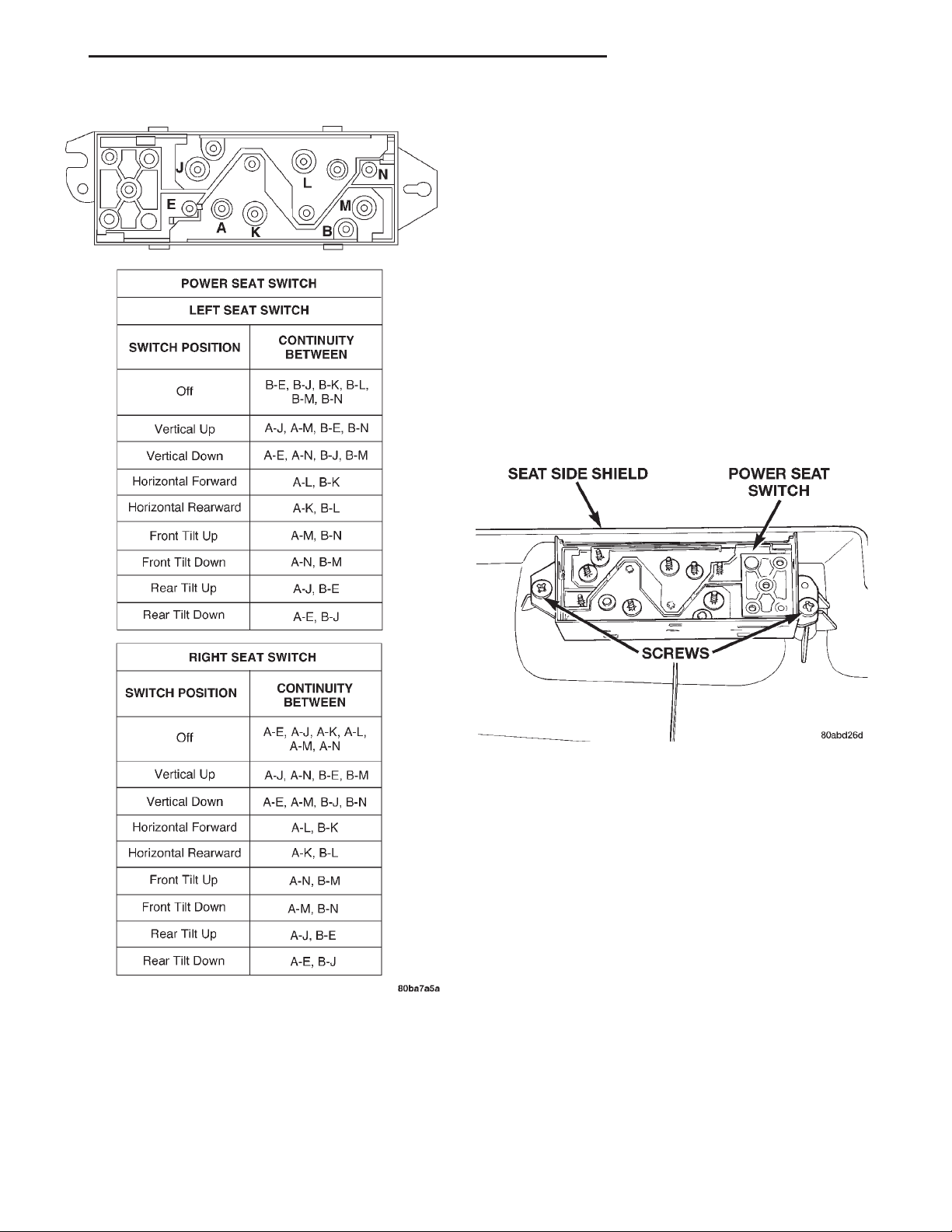
(3) Use an ohmmeter to test the continuity of the
power seat switches in each position. See the Power
Seat Switch Continuity chart (Fig. 1). If OK, see the
diagnosis for the Power Seat Adjuster and Motors in
this group. If not OK, replace the faulty power seat
switch module.
Page 3
XJ POWER SEAT SYSTEMS 8R - 3
DIAGNOSIS AND TESTING (Continued)
REMOVAL AND INSTALLATION
POWER SEAT SWITCH
(1) Disconnect and isolate the battery negative
cable.
(2) Remove the three screws that secure the seat
cushion side shield to the outboard seat cushion
frame.
(3) Pull the seat cushion side shield away from the
seat cushion frame far enough to access the power
seat switch wire harness connector.
(4) Unplug the wire harness connector from the
power seat switch.
(5) Remove the seat cushion side shield from the
seat.
(6) Remove the two screws that secure the power
seat switch to the inside of the seat cushion side
shield (Fig. 2).
Fig. 1 Power Seat Switch Continuity
Fig. 2 Power Seat Switch Remove/Install
Page 4
8R - 4 POWER SEAT SYSTEMS XJ
REMOVAL AND INSTALLATION (Continued)
(7) Remove the power seat switch from the seat
cushion side shield.
(8) Reverse the removal procedures to install.
Tighten the mounting screws to 2.2 N·m (20 in. lbs.).
POWER SEAT ADJUSTER AND MOTORS
(1) Move the seat to its fully raised and fully for-
ward position, if possible.
(2) Disconnect and isolate the battery negative
cable.
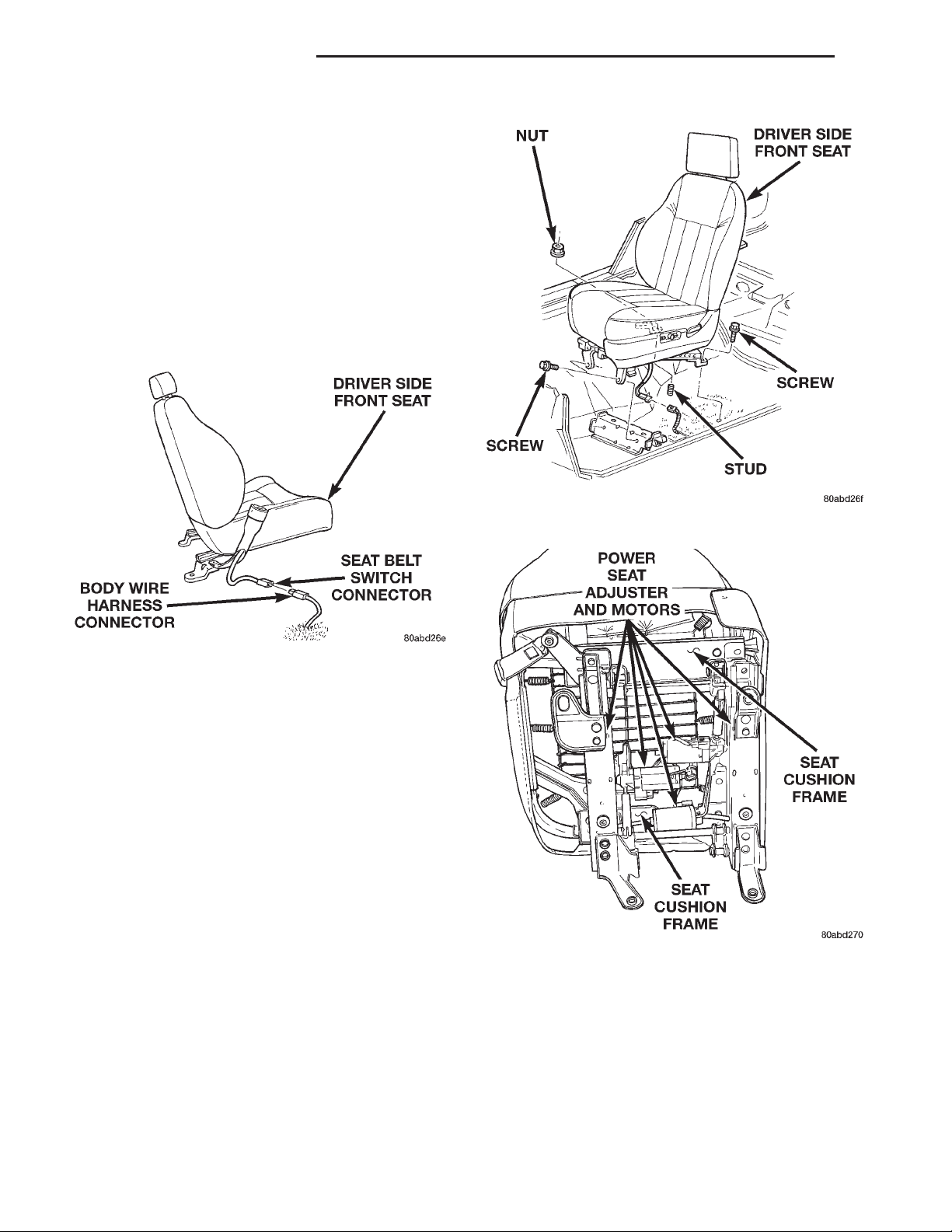
(3) Unplug the seat belt switch wire harness connector from the driver side seat belt buckle half on
the inboard side of the seat (Fig. 3).
Fig. 3 Driver Seat Belt Switch Connector
(4) Remove the two screws that secure the front of
the seat adjuster frame to the floor panel seat
mounting reinforcement (Fig. 4).
(5) Remove the screw that secures the outboard
rear of the seat adjuster frame to the floor panel.
(6) Remove the nut that secures the inboard rear
of the seat adjuster frame to the stud on the floor
panel.
(7) Unplug the power seat wire harness connector
from the body wire harness connector.
(8) Remove the driver side power seat and adjuster
assembly from the vehicle.
(9) Unplug the power seat wire harness connectors
at each of the three power seat motors.
(10) Remove the four nuts that secure the seat
adjuster and motors assembly to the seat cushion
frame (Fig. 5).
(11) Remove the adjuster and motors assembly
from the seat cushion frame.
(12) Reverse the removal procedures to install.
Tighten the seat mounting hardware as follows:
Fig. 4 Power Seat Remove/Install
Fig. 5 Power Seat Adjuster and Motors Remove/
Install
• Seat adjuster to seat cushion frame nuts - 25
N·m (18 ft. lbs.)
• Seat adjuster to floor panel screws - 27 N·m (20
ft. lbs.)
• Seat adjuster to floor panel nut - 40 N·m (30 ft.
lbs.).
 Loading...