

Page 1

XJ VEHICLE THEFT/SECURITY SYSTEMS 8Q - 1
VEHICLE THEFT/SECURITY SYSTEMS
TABLE OF CONTENTS
page page
GENERAL INFORMATION
INTRODUCTION ..........................1
SENTRY KEY IMMOBILIZER SYSTEM.........1
DESCRIPTION AND OPERATION
SENTRY KEY IMMOBILIZER MODULE.........1
SENTRY KEY IMMOBILIZER TRANSPONDER ...2
SENTRY KEY IMMOBILIZER SYSTEM
INDICATOR LAMP.......................3
GENERAL INFORMATION
INTRODUCTION
The Sentry Key Immobilizer System (SKIS) is
available factory-installed optional equipment for this
model. Following are some general descriptions of the
features and components of the SKIS. Refer to the
vehicle owner’s manual for more information on the
use and operation of the SKIS. Refer to 8W-30 - Fuel/
Ignition System in Group 8W - Wiring Diagrams for
complete circuit descriptions and diagrams.
SENTRY KEY IMMOBILIZER SYSTEM
The Sentry Key Immobilizer System (SKIS) is
designed to provide passive protection against unauthorized vehicle use by preventing the engine from
operating while the system is armed. The primary
components of this system are the Sentry Key Immobilizer Module (SKIM), the Sentry Key transponder,
the SKIS indicator lamp, and the Powertrain Control
Module (PCM).
The SKIM is installed on the steering column near
the ignition lock cylinder. The transponder is located
under the molded rubber cap on the head of the ignition key. The SKIS indicator lamp is located in the
instrument cluster.
The SKIS includes two valid Sentry Key transponders
from the factory. If the customer wishes, additional noncoded blank Sentry Keys are available. These blank
keys can be cut to match a valid ignition key, but the
engine will not start unless the key transponder is also
programmed to the vehicle using the Customer Learn
programming procedure or a DRBIIIt scan tool. The
SKIS will recognize no more than eight valid Sentry
Key transponders at any one time.
The SKIS performs a self-test each time the ignition switch is turned to the On position, and will
store Diagnostic Trouble Codes (DTCs) if a system
DIAGNOSIS AND TESTING
SENTRY KEY IMMOBILIZER SYSTEM.........3
SERVICE PROCEDURES
SENTRY KEY IMMOBILIZER SYSTEM
TRANSPONDER PROGRAMMING ...........4
REMOVAL AND INSTALLATION
SENTRY KEY IMMOBILIZER MODULE.........4
malfunction is detected. The SKIS can be diagnosed,
and any stored DTC can be retrieved using a
DRBIIIt scan tool as described in the proper Diagnostic Procedures manual.
DESCRIPTION AND OPERATION
SENTRY KEY IMMOBILIZER MODULE
The Sentry Key Immobilizer Module (SKIM) contains a Radio Frequency (RF) transceiver and a central processing unit, which includes the Sentry Key
Immobilizer System (SKIS) program logic. The SKIS
programming enables the SKIM to program and
retain in memory the codes of at least one, but no
more than eight electronically coded Sentry Key
transponders. The SKIS programming also enables
the SKIM to communicate over the Chrysler Collision
Detection (CCD) data bus network with the Powertrain Control Module (PCM), the instrument cluster
and/or the DRBIIIt scan tool.
The SKIM transmits and receives RF signals
through a tuned antenna enclosed within a molded
plastic ring formation that is integral to the SKIM
housing. When the SKIM is properly installed on the
steering column, the antenna ring is oriented around
the circumference of the ignition lock cylinder housing. This antenna ring must be located within eight
millimeters (0.31 inches) of the Sentry Key in order
to ensure proper RF communication between the
SKIM and the Sentry Key transponder.
For added system security, each SKIM is programmed with a unique “Secret Key” code and a
security code (PIN). The SKIM keeps the “Secret
Key” code in memory. This “Secret Key” code must be
transferred to the PCM memory during the initialization/programming of the SKIS when the vehicle is
manufactured, and each time the PCM is replaced
during vehicle service by the dealer technician. The
Page 2
8Q - 2 VEHICLE THEFT/SECURITY SYSTEMS XJ
DESCRIPTION AND OPERATION (Continued)
SKIM also transfers the “Secret Key” code to the
memory of each of the Sentry Key transponders during new key programming. The security code is used
by the assembly plant to access the SKIS for initialization, or by the dealer technician to access the system for service. The SKIM also stores in its memory
the Vehicle Identification Number (VIN), which it
learns through a CCD data bus message from the
PCM during initialization.
The SKIM and the PCM both use software that
includes a rolling code algorithm strategy, which
helps to reduce the possibility of unauthorized SKIS
disarming. The rolling code algorithm ensures security by preventing an override of the SKIS through
the unauthorized substitution of the SKIM or the
PCM. However, the use of this strategy also means
that replacement of either the SKIM or the PCM
units will require a system initialization procedure to
restore system operation.
When the ignition switch is turned to the On or Start
positions, the SKIM transmits an RF signal to excite
the Sentry Key transponder. The SKIM then listens for
a return RF signal from the transponder of the Sentry
Key that is inserted in the ignition lock cylinder. If the
SKIM receives an RF signal with valid “Secret Key” and
transponder identification codes, the SKIM sends a
“valid key” message to the PCM over the CCD data bus.
If the SKIM receives an invalid RF signal or no
response, it sends “invalid key” messages to the PCM.
The PCM will enable or disable engine operation based
upon the status of the SKIM messages.
The SKIM also sends messages to the instrument
cluster over the CCD data bus network to control the
SKIS indicator lamp. The SKIM sends messages to the
instrument cluster to turn the lamp on for about three
seconds when the ignition switch is turned to the On
position as a bulb test. After completion of the bulb test,
the SKIM sends bus messages to keep the lamp off for a
duration of about one second. Then the SKIM sends
messages to turn the lamp on or off based upon the
results of the SKIS self-tests. If the SKIS indicator
lamp comes on and stays on after the bulb test, it indicates that the SKIM has detected a system malfunction
and/or that the SKIS has become inoperative.
If the SKIM detects an invalid key when the ignition
switch is turned to the On position, it sends messages to
the instrument cluster to flash the SKIS indicator lamp.
The SKIM can also send messages to the instrument
cluster to flash the lamp and to generate a single audible chime tone. These functions serve as an indication
to the customer that the SKIS has been placed in its
“Customer Learn” programming mode. See Sentry Key
Immobilizer System Transponder Programming in this
group for more information on the “Customer Learn”
programming mode.
For diagnosis or initialization of the SKIM and the
PCM, a DRBIIIt scan tool and the proper Diagnostic
Procedures manual are required. The SKIM cannot
be repaired and, if faulty or damaged, the unit must
be replaced.
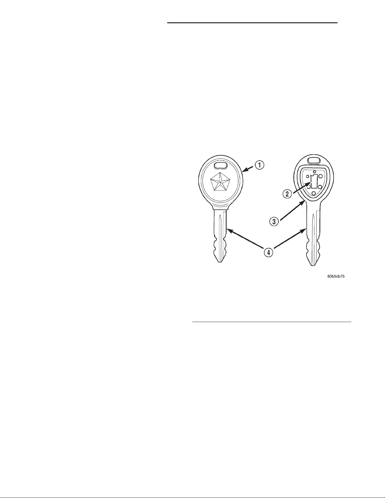
SENTRY KEY IMMOBILIZER TRANSPONDER
The Sentry Key Immobilizer System (SKIS) uses a
transponder that is integral to each of the two ignition keys that are supplied with the vehicle when it
is shipped from the factory. The transponder chip is
insulated within a nylon mount inserted in the head
of the key, and invisible beneath a molded rubber cap
(Fig. 1).
Fig. 1 Sentry Key Immobilizer Transponder
1 – MOLDED CAP
2 – TRANSPONDER
3 – MOLDED CAP REMOVED
4 – SENTRY KEY
Each Sentry Key transponder has a unique transponder identification code programmed into it by the
manufacturer. The Sentry Key Immobilizer Module
(SKIM) has a unique “Secret Key” code programmed
into it by the manufacturer. Each time a new Sentry
Key transponder is programmed, the SKIM learns
the transponder identification code from the transponder, and the transponder learns the “Secret Key”
code from the SKIM. Each of these codes is stored
within the transponder and in the nonvolatile memory of the SKIM. Therefore, blank keys for the SKIS
must be programmed and their transponder identification codes must be learned by and stored in the
SKIM memory, in addition to being cut to match the
mechanical coding of the ignition lock cylinder. See
Sentry Key Immobilizer System Transponder Programming in this group for more information.
Page 3

XJ VEHICLE THEFT/SECURITY SYSTEMS 8Q - 3
DESCRIPTION AND OPERATION (Continued)
The Sentry Key transponder is within the range of
the SKIM transceiver antenna ring when it is inserted
in the ignition lock cylinder. When the ignition switch is
turned to the Start or On positions, the SKIM transceiver issues a Radio Frequency (RF) signal that excites
the transponder chip. The transponder chip responds by
issuing an RF signal containing its transponder identification code and the “Secret Key” code. The SKIM
transceiver compares the transponder codes with the
codes stored in its memory to determine whether a valid
key is in the ignition lock cylinder.
The Sentry Key transponder cannot be repaired
and, if faulty or damaged, it must be replaced.
SENTRY KEY IMMOBILIZER SYSTEM INDICATOR LAMP
The Sentry Key Immobilizer System (SKIS) indicator lamp gives an indication when the SKIS is faulty
or when the vehicle has been immobilized due to the
use of an invalid ignition key. The lamp is controlled
by the instrument cluster circuitry based upon messages received from the Sentry Key Immobilizer
Module (SKIM) on the Chrysler Collision Detection
(CCD) data bus.
The SKIM sends messages to the instrument cluster to turn the lamp on for about three seconds when
the ignition switch is turned to the On position as a
bulb test. After completion of the bulb test, the SKIM
sends bus messages to keep the lamp off for a duration of about one second. Then the SKIM sends messages to the instrument cluster circuitry to turn the
lamp on or off based upon the results of the SKIS
self-tests. If the SKIS indicator lamp comes on and
stays on after the bulb test, it indicates that the
SKIM has detected a system malfunction and/or that
the SKIS has become inoperative.
If the SKIM detects an invalid key when the ignition
switch is turned to the On position, it sends messages to
the instrument cluster to flash the SKIS indicator lamp.
The SKIM can also send messages to the instrument
cluster to flash the lamp and to generate a single audible chime tone. These functions serve as an indication
to the customer that the SKIS has been placed in its
“Customer Learn” programming mode. See Sentry Key
Immobilizer System Transponder Programming in this
group for more information on the “Customer Learn”
programming mode.
The SKIS indicator lamp uses a replaceable incandescent bulb and bulb holder on the instrument cluster electronic circuit board. Refer to Group 8E Instrument Panel Systems for diagnosis and service
of a faulty SKIS indicator lamp. If the SKIS indicator
lamp comes on and stays on after the bulb test function, diagnosis of the SKIS should be performed with
a DRB scan tool and the proper Diagnostic Procedures manual.
DIAGNOSIS AND TESTING
SENTRY KEY IMMOBILIZER SYSTEM
WARNING:
REFER TO GROUP 8M - PASSIVE RESTRAINT SYSTEMS BEFORE ATTEMPTING ANY STEERING WHEEL,
STEERING COLUMN, OR INSTRUMENT PANEL COMPONENT DIAGNOSIS OR SERVICE. FAILURE TO TAKE
THE PROPER PRECAUTIONS COULD RESULT IN
ACCIDENTAL AIRBAG DEPLOYMENT AND POSSIBLE
PERSONAL INJURY.
NOTE: The following tests may not prove conclusive in the diagnosis of this system. The most reliable, efficient, and accurate means to diagnose the
Sentry Key Immobilizer System involves the use of
a DRB scan tool. Refer to the proper Diagnostic
Procedures manual for the procedures.
The Sentry Key Immobilizer System (SKIS) and
the Chrysler Collision Detection (CCD) data bus network should be diagnosed using a DRB scan tool.
The DRB will allow confirmation that the CCD data
bus is functional, that the Sentry Key Immobilizer
Module (SKIM) is placing the proper messages on the
CCD data bus, and that the Powertrain Control Module (PCM) and the instrument cluster are receiving
the CCD data bus messages. Refer to the proper
Diagnostic Procedures manual for the procedures.
Refer to 8W-39 - Vehicle Theft Security System in
Group 8W - Wiring Diagrams for complete circuit
descriptions and diagrams.
(1) Check the fuses in the fuseblock module. If OK,
go to Step 2. If not OK, repair the shorted circuit or
component as required and replace the faulty fuse.
(2) Disconnect and isolate the battery negative
cable. Unplug the wire harness connector at the
SKIM. Check for continuity between the ground circuit cavity of the SKIM wire harness connector and a
good ground. There should be continuity. If OK, go to
Step 3. If not OK, repair the open circuit to ground
as required.
(3) Connect the battery negative cable. Check for
battery voltage at the fused B(+) circuit cavity of the
SKIM wire harness connector. If OK, go to Step 4. If
not OK, repair the open circuit to the fuse in the
fuseblock module as required.
(4) Turn the ignition switch to the On position.
Check for battery voltage at the fused ignition switch
output (run/start) circuit cavity of the SKIM wire
harness connector. If OK, use a DRB scan tool and
the proper Diagnostic Procedures manual to complete
the diagnosis of the SKIS. If not OK, repair the open
circuit to the fuse in the fuseblock module as
required.
ON VEHICLES EQUIPPED WITH AIRBAGS,
Page 4
8Q - 4 VEHICLE THEFT/SECURITY SYSTEMS XJ
SERVICE PROCEDURES
SENTRY KEY IMMOBILIZER SYSTEM TRANSPONDER PROGRAMMING
Two programmed Sentry Key transponders are
included with the Sentry Key Immobilizer System
(SKIS) when it is shipped from the factory. The Sentry
Key Immobilizer Module (SKIM) can be programmed to
recognize up to six additional transponders, for a total
of eight Sentry Keys. The following “Customer Learn”
programming procedure for the programming of additional transponders requires access to at least two of
the valid Sentry Keys. If two valid Sentry Keys are not
available, Sentry Key programming will require the use
of a DRB scan tool and the proper Diagnostic Procedures manual.
CUSTOMER LEARN
(1)
Obtain the additional Sentry Key transponder
blank(s) that are to be programmed for the vehicle. Cut
the additional Sentry Key transponder blanks to match
the ignition lock cylinder mechanical key codes.
(2) Insert one of the two valid Sentry Key transponders into the ignition switch and turn the ignition switch to the On position.
After the ignition switch has been in the On posi-
(3)
tion for about three seconds, but no more than fifteen
seconds later, cycle the ignition switch back to the Off
position. Replace the first valid Sentry Key in the ignition lock cylinder with the second valid Sentry Key and
turn the ignition switch back to the On position.
(4) About ten seconds after the completion of Step
3, the SKIS indicator lamp will start to flash and a
single audible chime tone will sound to indicate that
the system has entered the “Customer Learn” programming mode.
(5) Within about fifty seconds of entering the “Customer Learn” programming mode, turn the ignition
switch to the Off position, replace the valid Sentry
Key with a blank Sentry Key transponder, and turn
the ignition switch back to the On position.
(6) About ten seconds after the completion of Step
5, a single audible chime tone will sound and the
SKIS indicator lamp will stop flashing and stay on
solid for about three seconds to indicate that the
blank Sentry Key transponder has been successfully
programmed. The SKIS will immediately return to
normal system operation following exit from the
“Customer Learn” programming mode.
(7) Go back to Step 2 and repeat this process for
each additional Sentry Key transponder blank to be
programmed.
If any of the above steps is not completed in the
proper sequence, or within the allotted time, the SKIS
will automatically exit the “Customer Learn” programming mode. The SKIS will also automatically exit the
“Customer Learn” programming mode if it sees a nonblank Sentry Key transponder when it should see a
blank, if it has already programmed eight valid Sentry
Keys, or if the ignition switch is turned to the Off position for more than about fifty seconds.
REMOVAL AND INSTALLATION
SENTRY KEY IMMOBILIZER MODULE
WARNING:
REFER TO GROUP 8M - PASSIVE RESTRAINT SYSTEMS BEFORE ATTEMPTING ANY STEERING WHEEL,
STEERING COLUMN, OR INSTRUMENT PANEL COMPONENT DIAGNOSIS OR SERVICE. FAILURE TO TAKE
THE PROPER PRECAUTIONS COULD RESULT IN
ACCIDENTAL AIRBAG DEPLOYMENT AND POSSIBLE
PERSONAL INJURY.
(1) Disconnect and isolate the battery negative
cable.
(2) Remove the knee blocker from the instrument
panel. See Knee Blocker in Group 8E - Instrument
Panel Systems for the procedures.
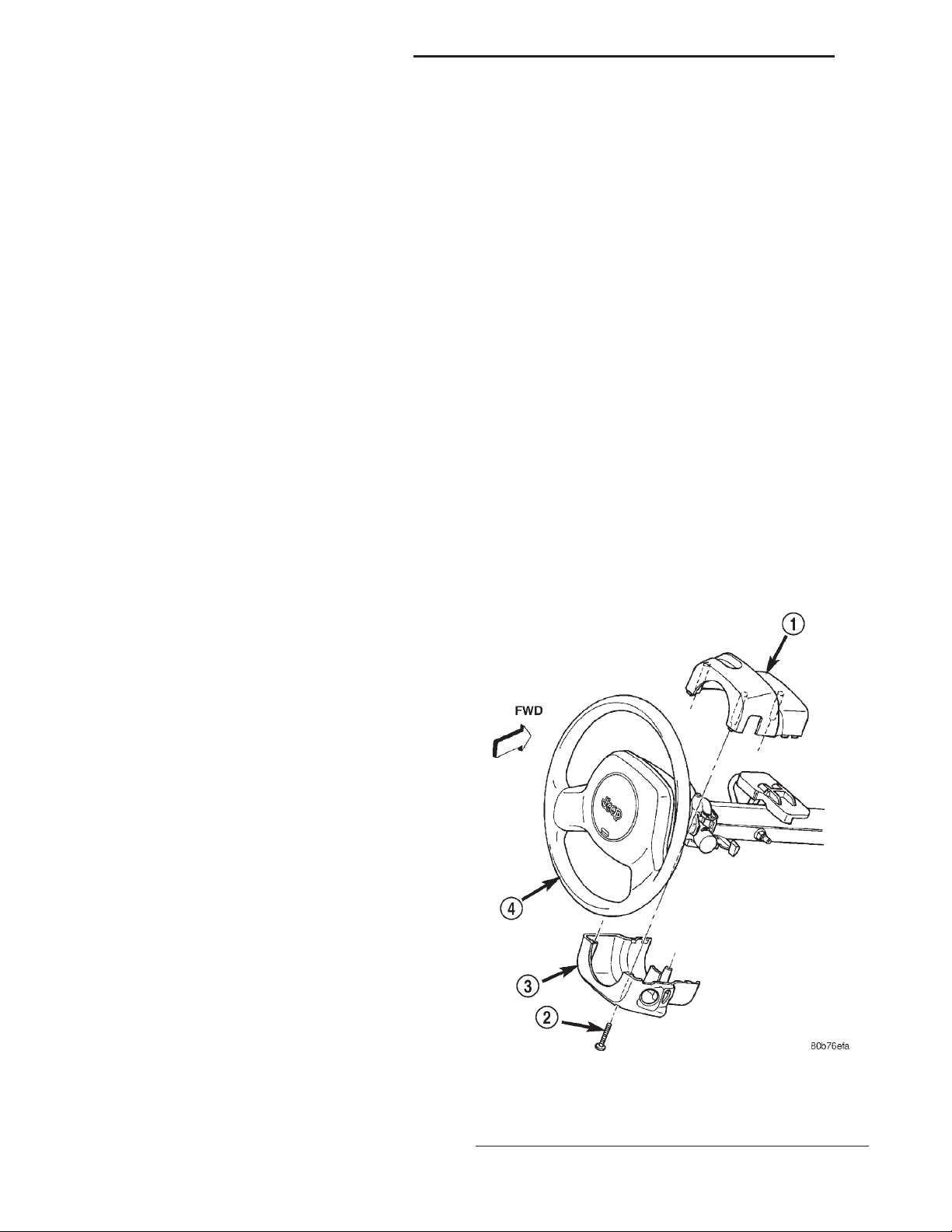
(3) Remove the three screws that secure the lower
steering column shroud to the upper shroud (Fig. 2).
Fig. 2 Steering Column Shrouds Remove/Install
1 – UPPER SHROUD
2 – SCREW (3)
3 – LOWER SHROUD
4 – STEERING WHEEL
ON VEHICLES EQUIPPED WITH AIRBAGS,
Page 5
XJ VEHICLE THEFT/SECURITY SYSTEMS 8Q - 5
REMOVAL AND INSTALLATION (Continued)
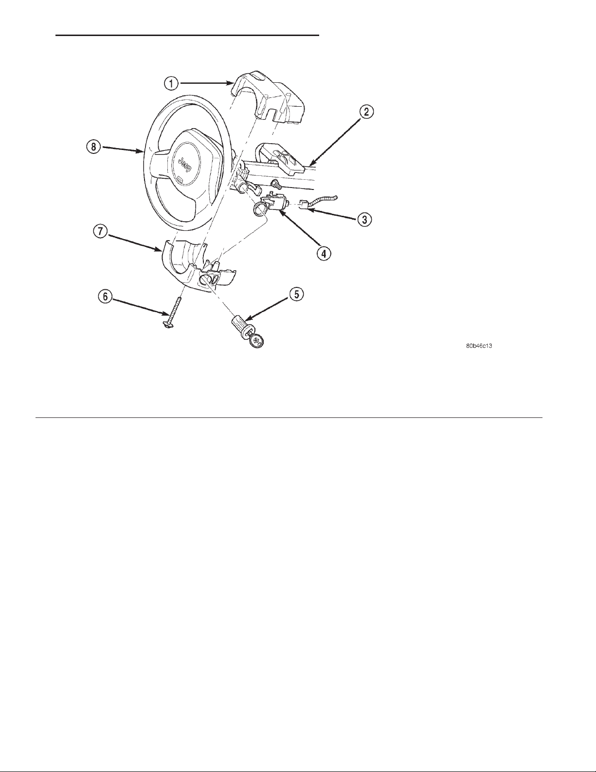
Fig. 3 Sentry Key Immobilizer Module Remove/Install
1 – UPPER SHROUD
2 – STEERING COLUMN
3 – WIRE HARNESS CONNECTOR
4 – SENTRY KEY IMMOBILIZER MODULE
(4) If the vehicle is equipped with a standard nontilt steering column, loosen the two upper steering
column mounting nuts. If the vehicle is equipped
with the optional tilt steering column, move the tilt
steering column to the fully lowered position.
(5) Remove both the upper and lower shrouds from
the steering column.
Disengage the steering column wire harness
(6)
retainer from the tab on the top of the Sentry Key
Immobilizer Module (SKIM) mounting bracket (Fig. 3).
(7) Unplug the wire harness connector from the
SKIM receptacle.
(8) The SKIM mounting bracket features a clip formation that secures the SKIM to the inboard lower
flange of the steering column jacket. Pull downward
on the connector end of the SKIM mounting bracket
to release this clip from the steering column jacket.
5 – IGNITION LOCK CYLINDER
6 – SCREW
7 – LOWER SHROUD
8 – STEERING WHEEL
(9) Rotate the SKIM and its mounting bracket
downwards and then to the side away from the steering column to slide the SKIM antenna ring from
around the ignition switch lock cylinder housing.
(10) Remove the SKIM from the vehicle.
(11) Reverse the removal procedures to install.
Tighten the non-tilt steering column mounting nuts
to 22 N·m (200 in. lbs.) and the steering column
shroud mounting screws to 2 N·m (18 in. lbs.).
NOTE: If the SKIM is replaced with a new unit, a
DRBIIIT scan tool and the proper Diagnostic Procedures manual MUST be used to initialize the new
SKIM and to program at least two Sentry Key
transponders.
Page 6

 Loading...