

Page 1

XJ POWER DISTRIBUTION SYSTEMS 8O - 1
POWER DISTRIBUTION SYSTEMS
TABLE OF CONTENTS
page page
DESCRIPTION AND OPERATION
POWER DISTRIBUTION SYSTEM.............1
POWER DISTRIBUTION CENTER.............2
IGNITION-OFF DRAW FUSE .................2
JUNCTION BLOCK ........................3
REMOVAL AND INSTALLATION
POWER DISTRIBUTION CENTER.............4
DESCRIPTION AND OPERATION
POWER DISTRIBUTION SYSTEM
DESCRIPTION
This group covers the various standard and
optional power distribution components used on this
model. The power distribution system for this vehicle
consists of the following components:
• Power Distribution Center (PDC)
• Junction Block (JB).
The power distribution system also incorporates
various types of circuit control and protection features, including:
• Automatic resetting circuit breakers
• Blade-type fuses
• Maxi fuse-type fusible links
• Relays.
Following are general descriptions of the major
components in the power distribution system. See the
owner’s manual in the vehicle glove box for more
information on the features and use of all of the
power distribution system components. Refer to the
index in this service manual for the location of complete circuit diagrams for the various power distribution system components.
IGNITION-OFF DRAW FUSE .................5
JUNCTION BLOCK ........................6
DISASSEMBLY AND ASSEMBLY
POWER DISTRIBUTION CENTER.............7
SPECIAL TOOLS
POWER DISTRIBUTION SYSTEMS ..........10
NOTE: This group covers both Left-Hand Drive
(LHD) and Right-Hand Drive (RHD) versions of this
model. Whenever required and feasible, the RHD
versions of affected vehicle components have been
constructed as mirror-image of the LHD versions.
While most of the illustrations used in this group
represent only the LHD version, the diagnostic and
service procedures outlined can generally be
applied to either version. Exceptions to this rule
have been clearly identified as LHD or RHD, if a
special illustration or procedure is required.
OPERATION
The power distribution system for this vehicle is
designed to provide safe, reliable, and centralized distribution points for the electrical current required to
operate all of the many standard and optional factory-installed electrical and electronic powertrain,
chassis, safety, security, comfort and convenience systems. At the same time, the power distribution system was designed to provide ready access to these
electrical distribution points for the vehicle technician to use when conducting diagnosis and repair of
faulty circuits. The power distribution system can
also prove useful for the sourcing of additional electrical circuits that may be required to provide the
electrical current needed to operate many accessories
that the vehicle owner may choose to have installed
in the aftermarket.
Page 2
8O - 2 POWER DISTRIBUTION SYSTEMS XJ
DESCRIPTION AND OPERATION (Continued)
POWER DISTRIBUTION CENTER
DESCRIPTION
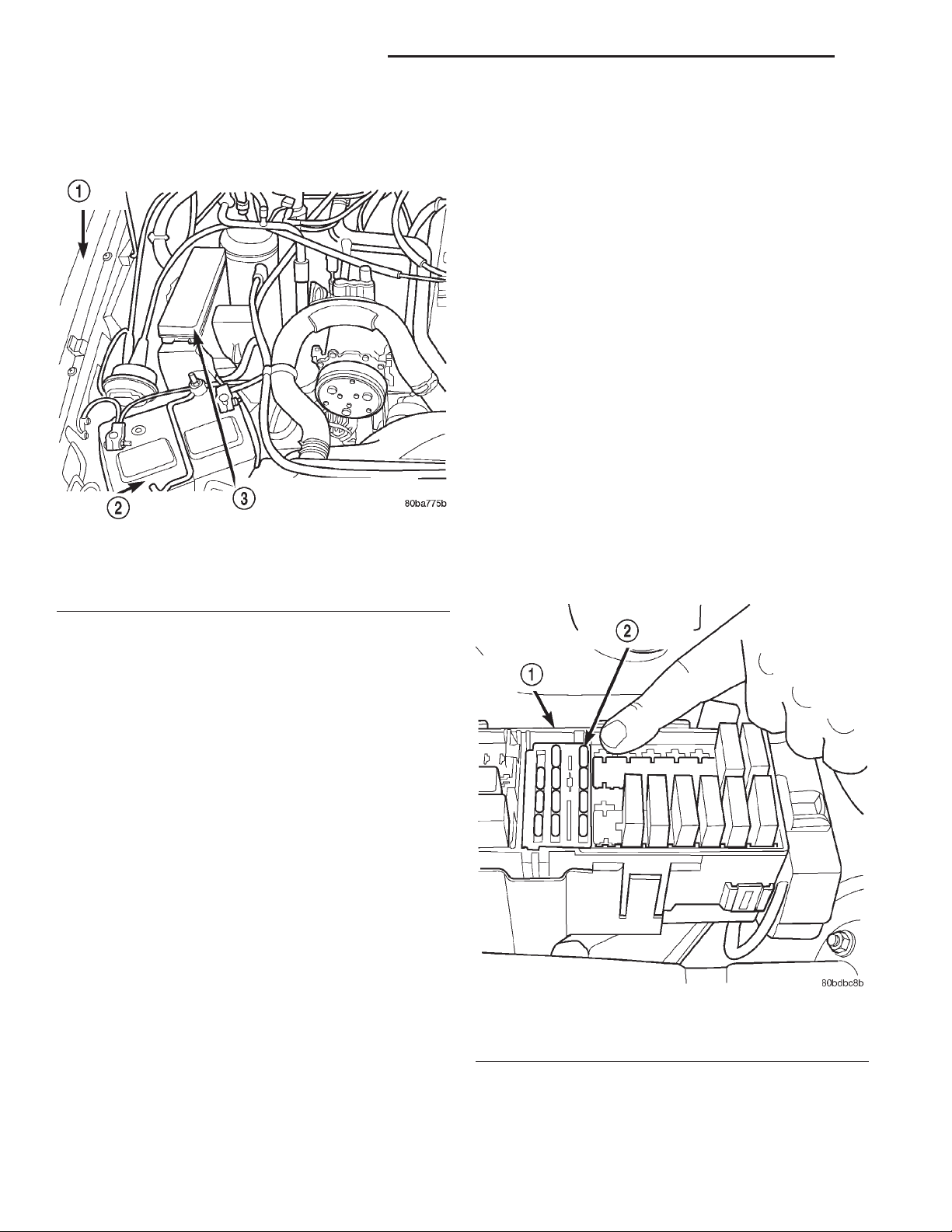
Fig. 1 Power Distribution Center Location
1 – LEFT FENDER
2 – BATTERY
3 – POWER DISTRIBUTION CENTER
replacement. The PDC main housing unit, the fuse
wedges, the fuse cassette and the bus bars cannot be
repaired and are only serviced as a unit with the
headlamp and dash wire harness. If the PDC main
housing unit, fuse wedges, fuse cassette or the bus
bars are faulty or damaged, the headlamp and dash
wire harness unit must be replaced.
OPERATION
All of the current from the battery and the generator output enters the PDC through two cables and
eyelets that are secured with a nut to the PDC B(+)
terminal stud located on one end of the PDC housing.
The PDC B(+) terminal stud cover is unlatched and
removed to access the battery and generator output
connection B(+) terminal stud. The PDC cover is
unlatched and opened or removed to access the fuses
or relays. Internal connection of all of the PDC circuits is accomplished by an intricate combination of
hard wiring and bus bars. Refer to Power Distribu-
tion in the index of this service manual for the location of complete PDC circuit diagrams.
IGNITION-OFF DRAW FUSE
DESCRIPTION
All of the electrical current distributed throughout
this vehicle is directed through the standard equipment Power Distribution Center (PDC) (Fig. 1). The
molded plastic PDC housing is located on the right
side of the engine compartment, just behind the battery. The PDC houses up to fourteen blade-type maxi
fuses, which replace all in-line fusible links. The PDC
also houses up to twelve blade-type mini fuses, and
up to eight International Standards Organization
(ISO) relays (four standard-type and four micro-type).
The PDC housing is secured to a stamped sheet
metal bracket in the engine compartment by mounting slots and tabs that are integral to the PDC housing. The PDC mounting bracket is secured with two
screws to the right front inner fender shield above
the right front wheel house. The PDC housing has a
molded plastic cover that includes two integral hinge
tabs on the inboard side, and an integral latch on the
outboard side. The PDC cover is easily opened or
removed for service access and has a convenient fuse
and relay layout map integral to the inside surface of
the cover to ensure proper component identification.
A separate molded plastic B(+) terminal stud cover is
secured by two integral tabs and a latch to one end
of the PDC housing.
The PDC cover, the PDC housing lower cover, the
PDC B(+) terminal stud cover, the PDC relay wedges
and the PDC relay cassettes are available for service
Fig. 2 Ignition-Off Draw Fuse
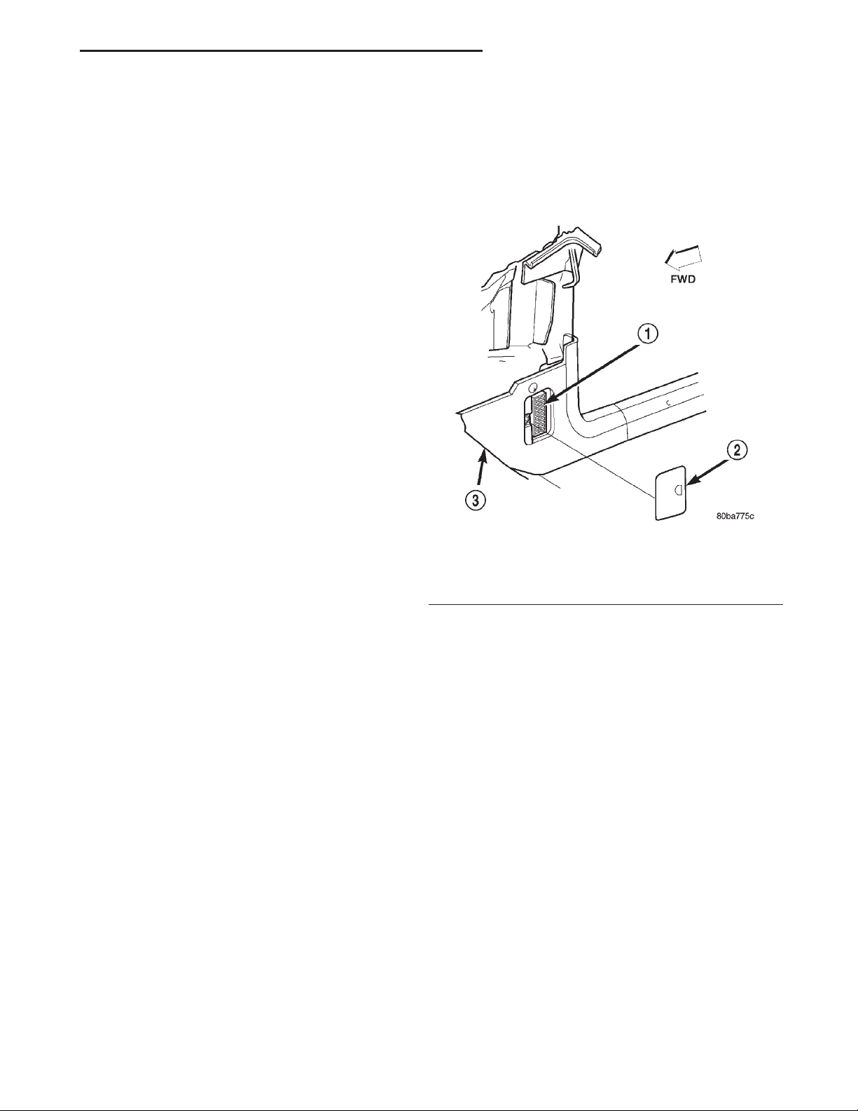
1 – POWER DISTRIBUTION CENTER
2 – IGNITION-OFF DRAW FUSE
All vehicles are equipped with an Ignition-Off
Draw (IOD) fuse (Fig. 2) that is removed from its
cavity in the Power Distribution Center (PDC) when
the vehicle is shipped from the factory. Dealer per-
Page 3
XJ POWER DISTRIBUTION SYSTEMS 8O - 3
DESCRIPTION AND OPERATION (Continued)
sonnel are to remove the IOD fuse from the storage
location and install it into PDC fuse cavity 16 as part
of the preparation procedures performed just prior to
new vehicle delivery.
The PDC has a molded plastic cover that can be
removed to provide service access to all of the fuses
and relays in the PDC. An integral latch and hinge
tabs are molded into the PDC cover for easy removal.
A fuse layout map is integral to the underside of the
PDC cover to ensure proper fuse and relay identification. The IOD fuse is a 15 ampere mini blade-type
fuse and, when removed, it is stored in a plastic fuse
holder formation that is molded into the underside of
the PDC cover.
OPERATION
The term ignition-off draw identifies a normal condition where power is being drained from the battery
with the ignition switch in the Off position. The IOD
fuse feeds the memory and sleep mode functions for
many of the electronic modules in the vehicle as well
as various other accessories that require battery current when the ignition switch is in the Off position,
including the clock. The only reason the IOD fuse is
removed is to reduce the normal IOD of the vehicle
electrical system during new vehicle transportation
and pre-delivery storage to reduce battery depletion,
while still allowing vehicle operation so that the
vehicle can be loaded, unloaded and moved as needed
by both vehicle transportation company and dealer
personnel.
The IOD fuse is removed from PDC fuse cavity 16
when the vehicle is shipped from the assembly plant.
Dealer personnel must install the IOD fuse when the
vehicle is being prepared for delivery in order to
restore full electrical system operation. Once the
vehicle is prepared for delivery, the IOD function of
this fuse becomes transparent and the fuse that has
been assigned the IOD designation becomes only
another Fused B(+) circuit fuse. The IOD fuse serves
no useful purpose to the dealer technician in the service or diagnosis of any vehicle system or condition,
other than the same purpose as that of any other
standard circuit protection device.
The IOD fuse can be used by the vehicle owner as
a convenient means of reducing battery depletion
when a vehicle is to be stored for periods not to
exceed about thirty days. However, it must be
remembered that removing the IOD fuse will not
eliminate IOD, but only reduce this normal condition.
If a vehicle will be stored for more than about thirty
days, the battery negative cable should be disconnected to eliminate normal IOD; and, the battery
should be tested and recharged at regular intervals
during the vehicle storage period to prevent the battery from becoming discharged or damaged. Refer to
Battery in the index of this service manual for the
location of additional service information covering
the battery.
JUNCTION BLOCK
DESCRIPTION
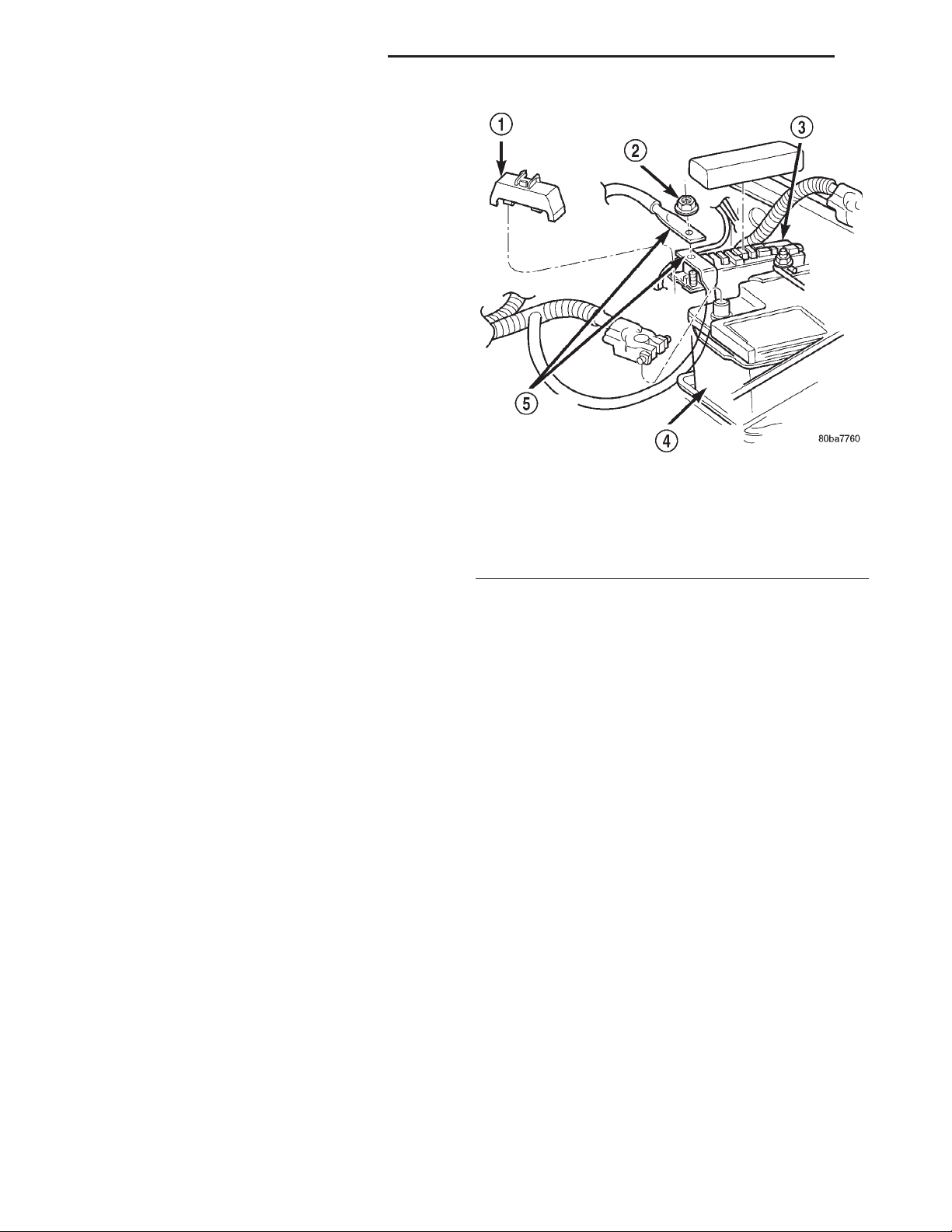
Fig. 3 Junction Block Location
1 – JUNCTION BLOCK
2 – FUSE ACCESS PANEL
3 – RIGHT COWL SIDE INNER TRIM PANEL
An electrical Junction Block (JB) is concealed
behind the right cowl side inner trim panel in the
passenger compartment of the vehicle (Fig. 3). The
JB combines the functions previously provided by a
separate fuseblock module and relay center. The JB
serves to simplify and centralize numerous electrical
components, as well as to distribute electrical current
to many of the accessory systems in the vehicle. It
also eliminates the need for numerous splice connections and serves in place of a bulkhead connector
between many of the engine compartment, instrument panel, and body wire harnesses. The JB houses
up to twenty-seven blade-type fuses (three standardtype and twenty-four mini-type), up to three bladetype automatic resetting circuit breakers, and four
International Standards Organization (ISO) relays
(three standard-type and one micro-type).
The molded plastic JB housing has integral mounting brackets that are secured with three nuts to
studs on the right cowl side inner panel below the
instrument panel. The right cowl side inner trim
panel is secured to a stud on the JB with a push nut.
A snap-fit fuse access panel can be removed for service of the JB fuses and also conceals the push nut. A
finger recess is molded into the front of the fuse
Page 4
8O - 4 POWER DISTRIBUTION SYSTEMS XJ
DESCRIPTION AND OPERATION (Continued)
access panel for easy removal, and a fuse puller and
spare fuse holders are located on the back of the fuse
access panel.
The JB unit cannot be repaired and is only serviced as an assembly. If any internal circuit or the JB
housing is faulty or damaged, the entire JB unit
must be replaced.
OPERATION
All of the circuits entering and leaving the JB do
so through up to ten wire harness connectors, which
are connected to the JB through integral connector
receptacles molded into the JB housing. Internal connection of all of the JB circuits is accomplished by an
intricate combination of hard wiring and bus bars.
Refer to Junction Block in the index of this service
manual for the location of complete JB circuit diagrams.
REMOVAL AND INSTALLATION
POWER DISTRIBUTION CENTER
The Power Distribution Center (PDC) main housing unit, the PDC fuse wedges, the PDC fuse cassette
and the PDC bus bars cannot be repaired and are
only serviced as a unit with the headlamp and dash
wire harness. If the PDC main housing unit, the fuse
wedge, the fuse cassette or the bus bars are faulty or
damaged, the entire PDC and headlamp and dash
wire harness unit must be replaced.
REMOVAL
(1) Disconnect and isolate the battery negative
cable.
(2) Disconnect each of the headlamp and dash wire
harness connectors. Refer to Connector Locations
in the index of this service manual for the location of
more information on the headlamp and dash wire
harness connector locations.
(3) Remove all of the fasteners that secure each of
the headlamp and dash wire harness ground eyelets
to the vehicle body and chassis components. Refer to
Connector Locations in the index of this service
manual for the location of more information on the
ground eyelet locations.
(4) Disengage each of the retainers that secure the
headlamp and dash wire harness to the vehicle body
and chassis components. Refer to Connector Loca-
tions in the index of this service manual for the location of more information on the headlamp and dash
wire harness retainer locations.
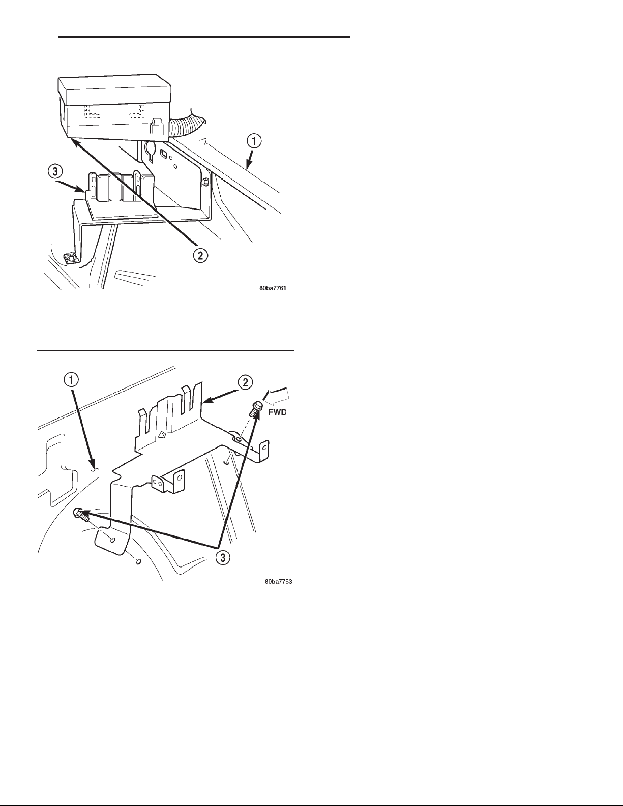
(5) Unlatch and remove the B(+) terminal stud
cover from the end of the PDC (Fig. 4).
(6) Remove the nut that secures the eyelets of the
battery wire harness PDC take outs to the PDC B(+)
terminal stud.
Fig. 4 Power Distribution Center Connections
1 – COVER
2 – NUT
3 – POWER DISTRIBUTION CENTER
4 – BATTERY
5 – BATTERY WIRE HARNESS PDC TAKE-OUTS
(7) Remove the battery wire harness PDC take out
eyelets from the B(+) terminal stud.
(8) Disengage the latches on the PDC mounting
bracket from the tabs on the PDC housing, and pull
the PDC housing upward to disengage the mounting
slots from the stanchions of the mounting bracket
(Fig. 5).
(9) Remove the PDC and the headlamp and dash
wire harness from the engine compartment as a unit.
(10) Remove the two screws that secure the PDC
mounting bracket to the right front inner fender (Fig.
6).
(11) Remove the PDC mounting bracket from the
right front inner fender.
INSTALLATION
NOTE: If the PDC is being replaced with a new unit,
be certain to transfer each of the fuses and relays
from the faulty PDC to the proper cavities of the
replacement PDC. Refer to Power Distribution in the
index of this service manual for the location of
complete PDC circuit diagrams and cavity assignments.
(1) Position the PDC mounting bracket onto the
right front inner fender.
(2) Install and tighten the two screws that secure
the PDC mounting bracket to the right front inner
fender. Tighten the screws to 8.1 N·m (72 in. lbs.).
Page 5
XJ POWER DISTRIBUTION SYSTEMS 8O - 5
REMOVAL AND INSTALLATION (Continued)
(5) Install the eyelets of the battery wire harness
PDC take outs onto the PDC B(+) terminal stud.
(6) Install and tighten the nut that secures the
eyelet of the battery wire harness PDC take outs to
the B(+) terminal stud. Tighten the nut to 10.8 N·m
(95 in. lbs.).
(7) Engage the tabs on the lower edge of the B(+)
terminal stud cover in the slots on the PDC housing,
then engage the latch on the top of the cover with
the latch receptacle on the PDC housing.
(8) Engage each of the retainers that secure the
headlamp and dash wire harness to the vehicle body
and chassis components. Refer to Connector Loca-
tions in the index of this service manual for the location of more information on the headlamp and dash
wire harness retainer locations.
(9) Install all of the fasteners that secure each of
the headlamp and dash wire harness ground eyelets
Fig. 5 Power Distribution Center Remove/Install
1 – RIGHT FENDER
2 – POWER DISTRIBUTION CENTER
3 – BRACKET
to the vehicle body and chassis components. Refer to
Connector Locations in the index of this service
manual for the location of more information on the
ground eyelet locations.
(10) Reconnect each of the headlamp and dash
wire harness connectors. Refer to Connector Loca-
tions in the index of this service manual for the location of more information on the headlamp and dash
wire harness connector locations.
(11) Reconnect the battery negative cable.
Fig. 6 PDC Mounting Bracket Remove/Install
1 – RIGHT FRONT INNER FENDER
2 – PDC MOUNTING BRACKET
3 – SCREW
(3) Position the PDC and the headlamp and dash
wire harness unit in the engine compartment.
(4) Engage the mounting slots on the PDC housing
with the stanchions of the PDC mounting bracket
and push the unit downward until the mounting
bracket latches engage the mounting tabs on the
PDC housing.
IGNITION-OFF DRAW FUSE
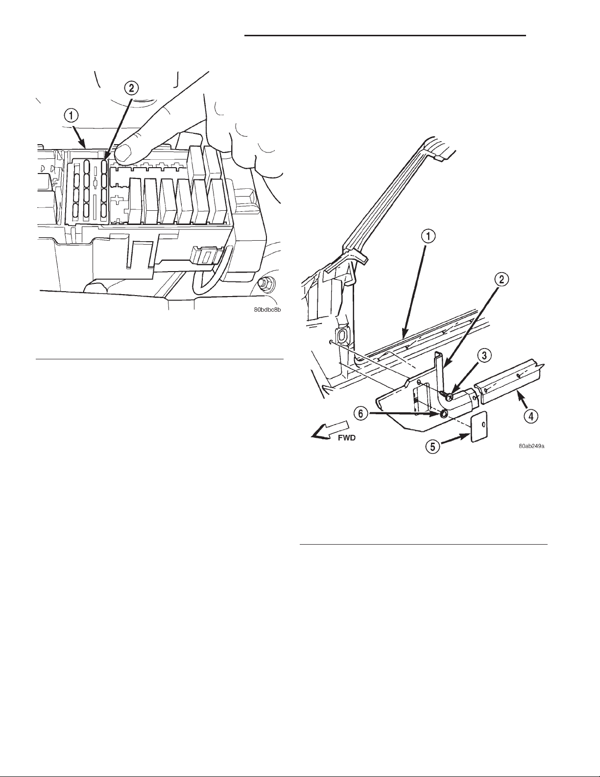
The Ignition-Off Draw (IOD) fuse is removed from
Power Distribution Center (PDC) fuse cavity 16 (Fig.
7) when the vehicle is shipped from the assembly
plant. Dealer personnel must install the IOD fuse
when the vehicle is being prepared for delivery in
order to restore full electrical system operation.
NOTE: When removing or installing the IOD fuse, it
is important that the ignition switch be in the Off
position. Failure to place the ignition switch in the
Off position can cause the radio display to become
scrambled when the IOD fuse is installed. Removing and installing the IOD fuse again with the ignition switch in the Off position will usually correct
the scrambled radio display condition.
REMOVAL
(1) Turn the ignition switch to the Off position.
(2) Unlatch and remove the cover from the PDC.
(3) Remove the IOD fuse from fuse cavity 16 of the
PDC.
(4) Store the removed IOD fuse by inserting the
terminal blades of the fuse into the plastic fuse
holder formation that is molded into the underside of
the PDC cover.
(5) Install and latch the cover onto the PDC.
Page 6
8O - 6 POWER DISTRIBUTION SYSTEMS XJ
REMOVAL AND INSTALLATION (Continued)
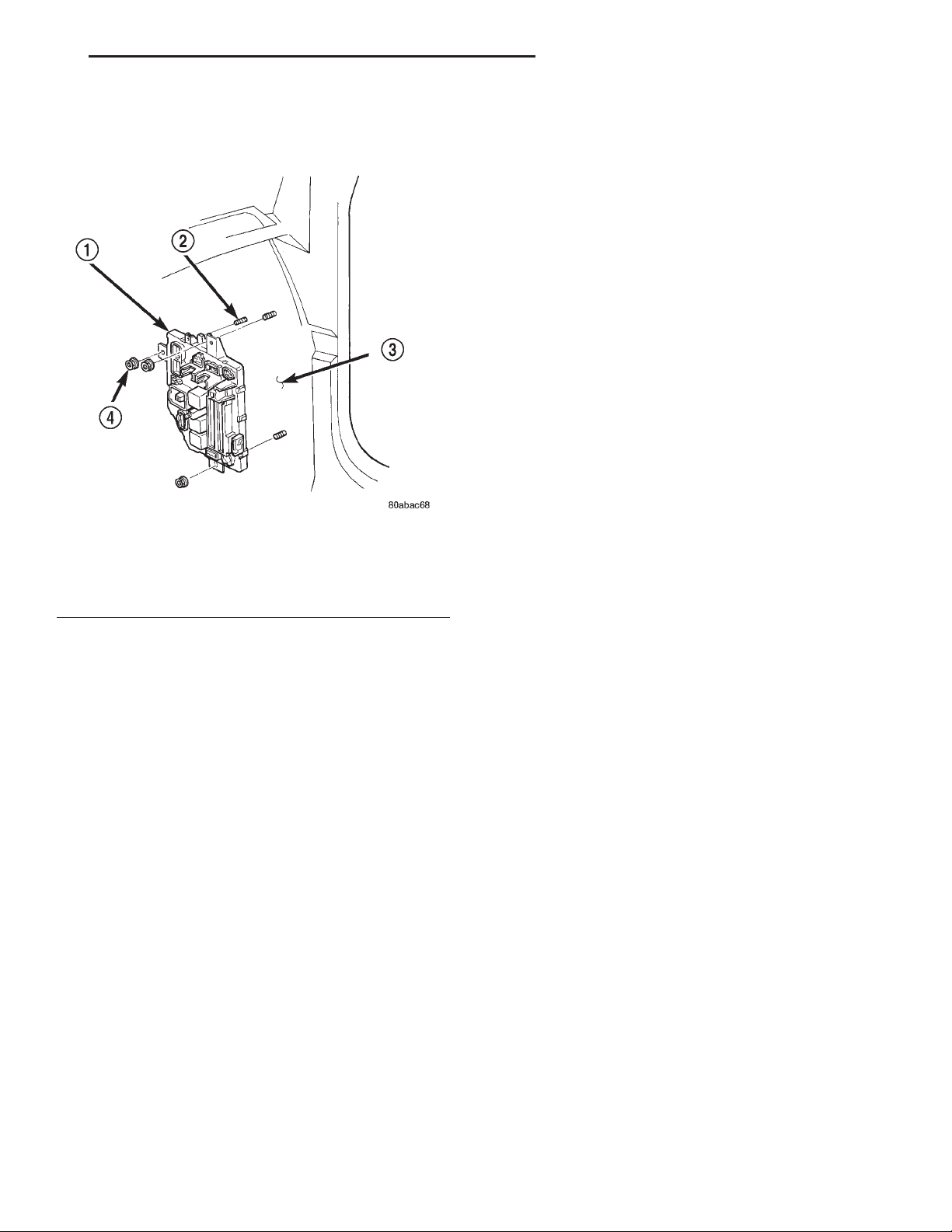
REMOVAL
(1) Disconnect and isolate the battery negative
cable.
(2) Remove the fuse access panel by unsnapping it
from the right cowl side inner trim panel (Fig. 8).
Fig. 7 Ignition-Off Draw Fuse
1 – POWER DISTRIBUTION CENTER
2 – IGNITION-OFF DRAW FUSE
INSTALLATION
(1) Turn the ignition switch to the Off position.
(2) Unlatch and remove the cover from the PDC.
(3) Remove the stored IOD fuse from the plastic
fuse holder formation that is molded into the underside of the PDC cover.
(4) Align the terminal blades of the IOD fuse with
the terminal receptacles in fuse cavity 16 of the PDC.
(5) Use a thumb to press the IOD fuse firmly down
into PDC fuse cavity 16.
(6) Install and latch the cover onto the PDC.
JUNCTION BLOCK
WARNING: ON VEHICLES EQUIPPED WITH AIRBAGS, DISABLE THE AIRBAG SYSTEM BEFORE
ATTEMPTING ANY STEERING WHEEL, STEERING
COLUMN, OR INSTRUMENT PANEL COMPONENT
DIAGNOSIS OR SERVICE. DISCONNECT AND ISOLATE THE BATTERY NEGATIVE (GROUND) CABLE,
THEN WAIT TWO MINUTES FOR THE AIRBAG SYSTEM CAPACITOR TO DISCHARGE BEFORE PERFORMING FURTHER DIAGNOSIS OR SERVICE. THIS
IS THE ONLY SURE WAY TO DISABLE THE AIRBAG
SYSTEM. FAILURE TO TAKE THE PROPER PRECAUTIONS COULD RESULT IN ACCIDENTAL AIRBAG DEPLOYMENT AND POSSIBLE PERSONAL
INJURY.
Fig. 8 Right Cowl Side Inner Trim Remove/Install
1 – RIGHT FRONT DOOR SILL
2 – COWL SIDE TRIM PANEL
3 – SCREW
4 – SILL TRIM
5 – FUSE ACCESS PANEL
6 – PUSH-NUT
(3) Remove the push nut that secures the right
cowl side inner trim panel to the mounting stud on
the Junction Block (JB).
(4) Remove the screw located above the fuse access
opening that secures the trim panel to the right cowl
side inner panel.
(5) Remove the screw that secures the right cowl
side inner trim panel and right front door sill trim to
the door opening sill.
(6) Remove the trim from the right cowl side inner
panel.
(7) Remove the screw that secures the lower
instrument panel wire harness connector to the JB.
(8) Disconnect all of the wire harness connectors
from the connector receptacles on the JB.
Page 7
XJ POWER DISTRIBUTION SYSTEMS 8O - 7
REMOVAL AND INSTALLATION (Continued)
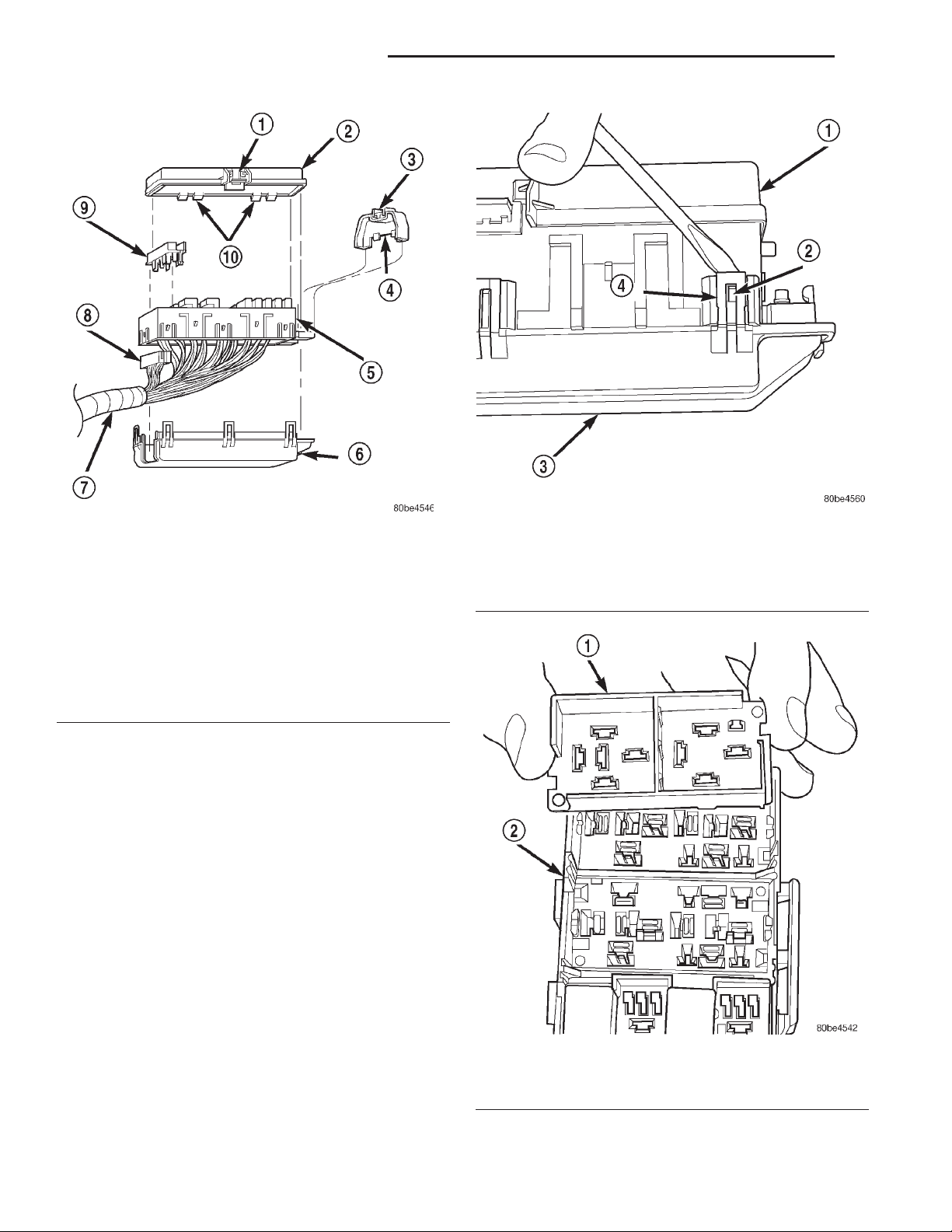
(9) Remove the three nuts that secure the JB to
the mounting studs on the right cowl side inner
panel (Fig. 9).
Fig. 9 Junction Block Remove/Install
1 – JUNCTION BLOCK
2 – STUD
3 – RIGHT COWL SIDE INNER PANEL
4 – NUT
(10) Remove the JB from the mounting studs on
the right cowl side inner panel.
sill trim to the door opening sill. Tighten the screw to
2.2 N·m (20 in. lbs.).
(7) Install and tighten the screw located above the
fuse access opening that secures the trim panel to
the right cowl side inner panel. Tighten the screw to
2.2 N·m (20 in. lbs.).
(8) Install the push nut that secures the right cowl
side inner trim panel to the mounting stud on the
JB.
(9) Install the fuse access panel by snapping it
onto the right cowl side inner trim panel.
(10) Reconnect the battery negative cable.
DISASSEMBLY AND ASSEMBLY
POWER DISTRIBUTION CENTER
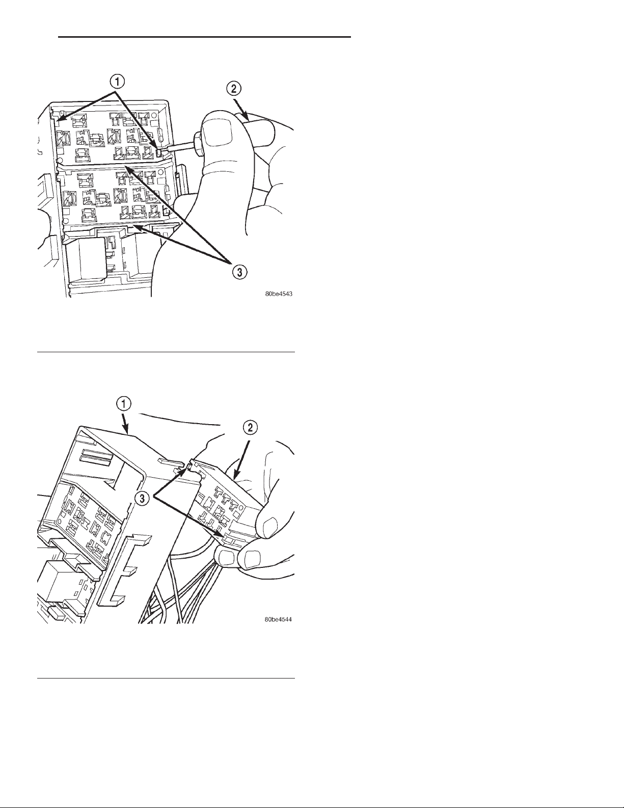
The Power Distribution Center (PDC) cover, the
PDC housing lower cover, the PDC relay wedges, the
PDC relay cassettes and the PDC B(+) terminal stud
cover are available for service replacement (Fig. 10).
The PDC cover and B(+) terminal stud cover can be
simply unlatched and removed from the PDC housing
without the PDC being removed or disassembled.
Service of the remaining PDC components requires
that the PDC be removed from its mounting and disassembled. Refer to Wiring Repair in the index of
this service manual for the location of the wiring
repair procedures.
DISASSEMBLY
INSTALLATION
NOTE: If the Junction Block (JB) is being replaced
with a new unit, be certain to transfer each of the
fuses, circuit breakers and relays from the faulty JB
to the proper cavities of the replacement JB. Refer
to Junction Block in the index of this service manual for the location of complete circuit diagrams
and cavity assignments for the JB.
(1) Position the JB onto the mounting studs
located on the right cowl side inner panel.
(2) Install and tighten the three nuts that secure
the JB to the mounting studs on the right cowl side
inner panel. Tighten the nuts to 2.7 N·m (24 in. lbs.).
(3) Reconnect all of the wire harness connectors to
the proper connector receptacles on the JB.
(4) Install and tighten the screw that secures the
lower instrument panel wire harness connector to the
JB connector receptacle. Tighten the screw to 3.5
N·m (31 in. lbs.).
(5) Position the trim onto the right cowl side inner
panel.
(6) Install and tighten the screw that secures the
right cowl side inner trim panel and right front door
PDC HOUSING LOWER COVER
(1) Disconnect and isolate the battery negative
cable.
(2) Unlatch and remove the cover from the PDC.
(3) Unlatch and remove the B(+) terminal stud
cover from the PDC.
(4) Remove the nut that secures the two battery
wire harness PDC take out eyelets to the B(+) terminal stud of the PDC.
(5) Remove the battery wire harness PDC take out
eyelets from the PDC B(+) terminal stud.
(6) Disengage the latches on the PDC mounting
bracket from the tabs on the PDC housing, and pull
the PDC housing upward to disengage the mounting
slots from the stanchions of the mounting bracket.
(7) Using a trim stick or another suitable wide
flat-bladed tool, gently pry the latches on each side
and one end of the PDC housing that secure the
housing lower cover to the PDC and remove the
housing lower cover (Fig. 11).
PDC RELAY WEDGE
(1) Remove the PDC housing lower cover.
(2) Remove each of the relays from the PDC relay
wedge to be removed.
Page 8
8O - 8 POWER DISTRIBUTION SYSTEMS XJ
DISASSEMBLY AND ASSEMBLY (Continued)
Fig. 10 Power Distribution Center Components
1–LATCH
2 – COVER
3–LATCH
4 – B(+) TERMINAL STUD COVER
5 – PDC HOUSING
6 – HOUSING LOWER COVER (TYPICAL)
7 – WIRE HARNESS
8 – RELAY CASSETTE (TYPICAL)
9 – RELAY WEDGE (TYPICAL)
10 – HINGE TABS
(3) From the bottom of the PDC housing, use a
small screwdriver or a terminal pick tool (Special
Tool Kit 6680) to release the two latches (yellow) that
secure the relay wedge to the PDC relay cassette.
(4) From the top of the PDC housing, remove the
relay wedge from the PDC relay cassette (Fig. 12).
PDC RELAY CASSETTE
(1) Remove the relay wedge from the PDC relay
cassette to be removed.
NOTE: It may be necessary to remove relay cassettes that are not being serviced from the PDC
housing in order to obtain sufficient clearance to
service the faulty relay cassette. The same service
procedure is repeated as necessary to remove each
of the interfering relay wedges and relay cassettes
from the PDC housing.
(2) From the top of the PDC housing, use a small
screwdriver or a terminal pick tool (Special Tool Kit
6680) to release the two latches that secure the relay
cassette in the PDC (Fig. 13).
Fig. 11 PDC Housing Lower Cover Remove/Install
1 – PDC HOUSING
2–TAB
3 – PDC HOUSING LOWER COVER
4–LATCH
Fig. 12 PDC Relay Wedge Remove/Install
1 – RELAY WEDGE (TYPICAL)
2 – PDC HOUSING
(3) Gently and evenly press the relay cassette
down through the PDC housing.
Page 9
XJ POWER DISTRIBUTION SYSTEMS 8O - 9
DISASSEMBLY AND ASSEMBLY (Continued)
ASSEMBLY
PDC RELAY CASSETTE
(1) Move the faulty PDC relay cassette with its
wiring away from the bottom of the PDC housing far
enough to allow the replacement relay cassette to be
installed into the PDC.
(2) Using the faulty relay cassette as a guide, be
certain that the replacement relay cassette is correctly oriented before installing it into the PDC housing.
(3) From the bottom of the PDC housing, align and
insert the replacement relay cassette into the PDC.
Press the relay cassette up into the PDC until both
of the latches are fully engaged.
CAUTION: Proper care must be taken to be certain
that the wiring and terminals from the faulty PDC
Fig. 13 PDC Relay Cassette Latches
1 – LATCHES
2 – FROM SPECIAL TOOL KIT 6680
3 – PDC RELAY CASSETTES (TYPICAL)
(4) From the bottom of the PDC housing, remove
the relay cassette from the PDC (Fig. 14).
relay cassette are installed in the correct terminal
cavities of the replacement relay cassette. To prevent mistakes it is recommended that the wiring
and terminals be removed from the faulty relay cassette one cavity at a time, repaired or spliced as
necessary, then installed securely into the correct
cavity of the replacement relay cassette. If you are
not absolutely certain into which cavity a terminal
should be installed, refer to Power Distribution in
the index of this service manual for the location of
complete circuit diagrams covering the PDC.
Fig. 14 PDC Relay Cassette Remove/Install
1 – PDC HOUSING
2 – PDC RELAY CASSETTE (TYPICAL)
3 – LATCHES
CAUTION: Do not remove the wiring and terminals
from the terminal cavities of the faulty PDC relay
cassette at this time. Refer to the Assembly procedure that follows for the proper procedures for
transferring the wiring and terminals to the replacement PDC relay cassette.
(4) While pulling gently on the wire from the bottom of the faulty PDC relay cassette, use a terminal
pick tool (Special Tool Kit 6680) from the top of the
relay cassette to release the latch that secures the
terminal in the relay cassette terminal cavity (Fig.
15).
(5) From the bottom of the faulty PDC relay cassette, remove the wire and terminal from the relay
cassette terminal cavity.
(6) Make all necessary repairs and splices to the
wire for the removed terminal. Refer to Wiring
Repair in the index of this service manual for the
location of the wiring repair procedures.
(7) From the bottom of the PDC housing, align and
insert the removed wire and terminal into the correct
terminal cavity of the replacement relay cassette.
Push the wire and terminal up into the relay cassette
terminal cavity until it is fully engaged by the latch.
(8) Repeat Step 4, Step 5, Step 6 and Step 7 one
wire and terminal at a time until each of the wires
and terminals have been transferred from the faulty
PDC relay cassette into the replacement relay cassette.
(9) Install the PDC relay wedge into the replacement PDC relay cassette.
Page 10
8O - 10 POWER DISTRIBUTION SYSTEMS XJ
DISASSEMBLY AND ASSEMBLY (Continued)
(2) Press the PDC housing lower cover gently and
evenly onto the PDC until each of the latches that
secure the cover to the PDC is fully engaged.
(3) Engage the mounting slots on the PDC housing
with the stanchions of the PDC mounting bracket
and push the unit downward until the mounting
bracket latches fully engage the mounting tabs on
the PDC housing.
(4) Install the battery wire harness PDC take out
eyelets over the PDC B(+) terminal stud.
(5) Install and tighten the nut that secures the
eyelets of the battery wire harness PDC take outs to
the B(+) terminal stud. Tighten the nut to 10.8 N·m
(95 in. lbs.).
(6) Install the B(+) terminal stud cover onto the
PDC.
(7) Install the cover onto the PDC.
(8) Reconnect the battery negative cable.
Fig. 15 PDC Relay Cassette Terminal Remove/Install
1 – TERMINAL CAVITIES (TYPICAL)
2 – PDC RELAY CASSETTE (TYPICAL)
3 – TERMINAL LATCHES (TYPICAL)
4 – FROM SPECIAL TOOL KIT 6680
PDC RELAY WEDGE
(1) From the top of the PDC housing, align and
insert the PDC relay wedge latch arms into the correct cavities in the relay cassette.
(2) Gently and evenly press the PDC relay wedge
down into the relay cassette until both of the latches
are fully engaged.
(3) Install each of the removed relays into the
proper cavities of the PDC relay wedge.
(4) Install the PDC housing lower cover.
PDC HOUSING LOWER COVER
(1) Align the PDC housing lower cover to the bottom of the PDC.
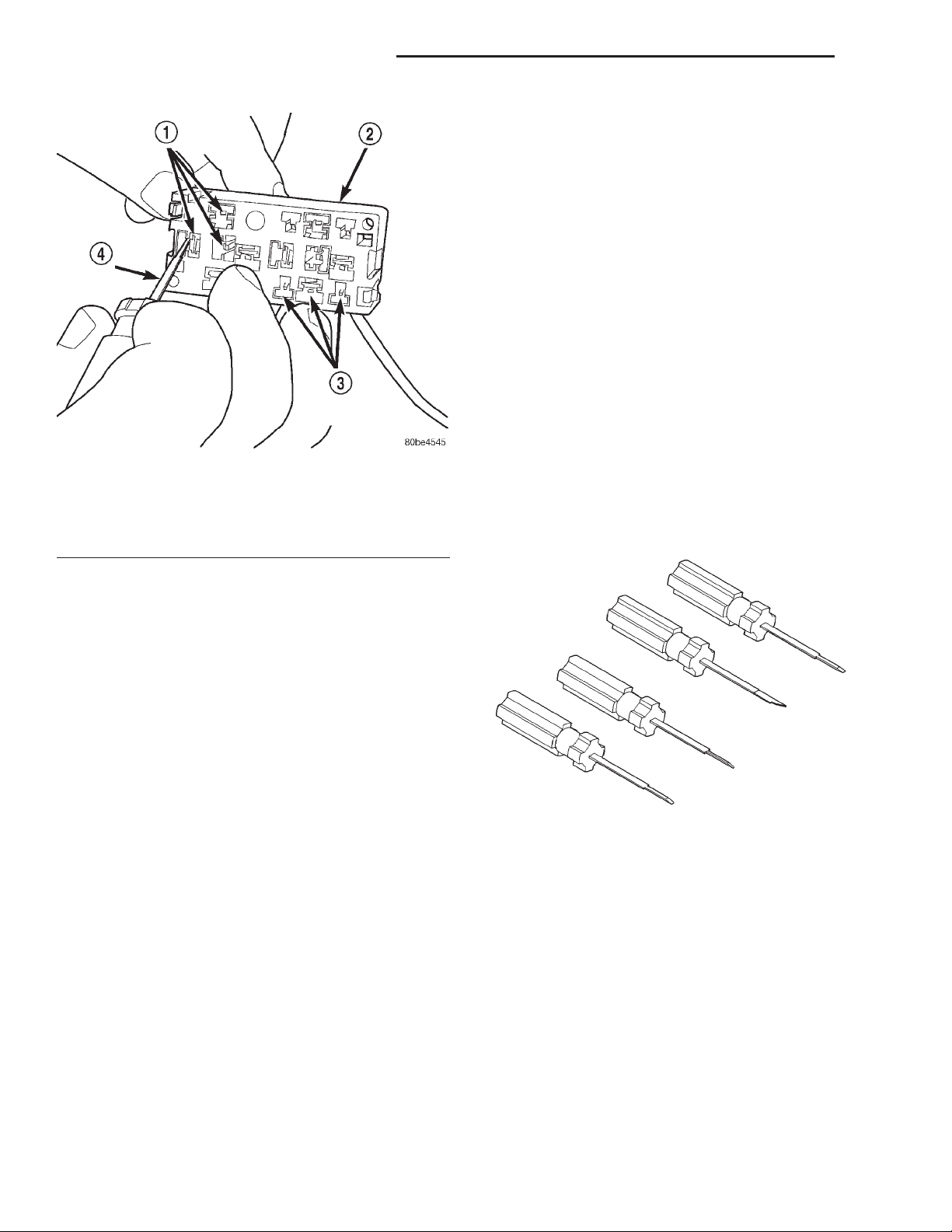
SPECIAL TOOLS
POWER DISTRIBUTION SYSTEMS
Terminal Pick Kit 6680
 Loading...