

Page 1
XJ ELECTRICALLY HEATED SYSTEMS 8N - 1
ELECTRICALLY HEATED SYSTEMS
CONTENTS
page page
HEATED SEAT SYSTEM .................... 8 REAR WINDOW DEFOGGER SYSTEM ......... 1
REAR WINDOW DEFOGGER SYSTEM
INDEX
page page
GENERAL INFORMATION
INTRODUCTION ......................... 1
REAR WINDOW DEFOGGER SYSTEM ........ 1
DESCRIPTION AND OPERATION
DEFOGGER RELAY ....................... 3
DEFOGGER SWITCH ......................2
INSTRUMENT CLUSTER ................... 2
OUTSIDE MIRROR HEATING GRID ........... 2
REAR GLASS HEATING GRID ...............2
DIAGNOSIS AND TESTING
DEFOGGER RELAY ....................... 4
GENERAL INFORMATION
INTRODUCTION
An electrically heated rear window defogger and
electrically heated outside rear view mirrors are
available factory-installed options on this model.
Refer to 8W-48 - Rear Window Defogger and 8W-62 Power Mirrors in Group 8W - Wiring Diagrams for
complete circuit descriptions and diagrams.
NOTE: This group covers both Left-Hand Drive
(LHD) and Right-Hand Drive (RHD) versions of this
model. Whenever required and feasible, the RHD
versions of affected vehicle components have been
constructed as mirror-image of the LHD versions.
While most of the illustrations used in this group
represent only the LHD version, the diagnostic and
service procedures outlined can generally be
applied to either version. Exceptions to this rule
have been clearly identified as LHD or RHD, if a
special illustration or procedure is required.
DEFOGGER SWITCH ......................4
DEFOGGER SYSTEM ..................... 3
INSTRUMENT CLUSTER ................... 5
REAR GLASS HEATING GRID ...............3
SERVICE PROCEDURES
REAR GLASS HEATING GRID REPAIR ........ 6
REMOVAL AND INSTALLATION
DEFOGGER RELAY ....................... 7
DEFOGGER SWITCH ......................6
REAR WINDOW DEFOGGER SYSTEM
The rear window defogger system will only operate
when the ignition switch is in the On position. When
the defogger switch is in the On position, an electric
heater grid on the rear window glass is energized.
Vehicles with the heated mirror options also have
heater grids located behind the outside rear view
mirror glass. Each of these grids produce heat to help
clear the rear window glass and outside rear view
mirrors of ice, snow, or fog.
The defogger system is controlled by a switch
installed in the instrument panel accessory switch
bezel, which is located near the bottom of the instrument panel center bezel area, below the heater and
air conditioner controls. An amber indicator lamp in
the switch button will light to indicate when the
defogger system is turned on. The instrument cluster
circuitry, which contains the defogger system timer
logic, monitors the state of the defogger switch
through a hard-wired input. The instrument cluster
circuitry controls the defogger system through a
hard-wired control output to the defogger relay.
The defogger system will be automatically turned
off after a programmed time interval of about ten
minutes. After the initial time interval has expired, if
Page 2

8N - 2 ELECTRICALLY HEATED SYSTEMS XJ
GENERAL INFORMATION (Continued)
the defogger switch is turned on again during the
same ignition cycle, the defogger system will automatically turn off after about five minutes.
The defogger system will automatically shut off if
the ignition switch is turned to the Off position, or it
can be turned off manually by depressing the instrument panel switch. Following are general descriptions of the major components in the defogger
system. Refer to the owner’s manual in the vehicle
glove box for more information on the features, use
and operation of the defogger system.
DESCRIPTION AND OPERATION
REAR GLASS HEATING GRID
The heated rear window glass has two electrically
conductive vertical bus bars and a series of horizontal grid lines made of a silver-ceramic material,
which is baked on and bonded to the inside surface of
the glass. The grid lines and bus bars comprise a
parallel electrical circuit.
When the rear window defogger switch is placed in
the On position, electrical current is directed to the
rear window grid lines through the bus bars. The
grid lines heat the rear window to clear the surface
of fog or snow. Protection for the heated grid circuit
is provided by a fuse in the Power Distribution Center (PDC).
The grid lines and bus bars are highly resistant to
abrasion. However, it is possible for an open circuit
to occur in an individual grid line, resulting in no
current flow through the line.
The grid lines can be damaged or scraped off with
sharp instruments. Care should be taken when cleaning the glass or removing foreign materials, decals,
or stickers from the glass. Normal glass cleaning solvents or hot water used with rags or toweling is recommended.
A repair kit is available to repair the grid lines and
bus bars, or to reinstall the heated glass pigtail
wires.
OUTSIDE MIRROR HEATING GRID
Vehicles equipped with the optional heated mirror
package have an electric heating grid located behind
the mirror glass of each outside rear view mirror.
The heated mirrors are controlled by the rear window defogger switch. Electrical current is directed to
the heating grid inside the mirror only when the rear
window defogger switch is in the On position.
If the outside mirror heating grids and the rear
window heating grid are all inoperative, diagnosis of
the rear window defogger system should be performed as described in this group. If the outside mirror heating grids are inoperative, but the rear
window heating grid is operating as designed, refer
to Power Mirror in the Diagnosis and Testing section
of Group 8T - Power Mirror Systems for diagnosis of
the mirror heating grids.
The heating grid behind each outside mirror glass
cannot be repaired and, if faulty or damaged, the
entire power mirror unit must be replaced. Refer to
Power Mirror in the Removal and Installation section
of Group 8T - Power Mirror Systems for the service
procedures.
DEFOGGER SWITCH
The rear window defogger switch is installed in the
instrument panel accessory switch bezel, which is
located near the bottom of the instrument panel center bezel area, below the heater and air conditioner
controls. The momentary-type switch provides a
hard-wired ground signal to the instrument cluster
each time it is depressed. The instrument cluster
rear window defogger timer and logic circuitry
responds by energizing or de-energizing the rear window defogger relay.
Energizing the rear window defogger relay provides electrical current to the rear window defogger
grid and, if the vehicle is so equipped, the outside
rear view mirror heating grids. An amber indicator
lamp in the defogger switch, which lights to indicate
when the defogger system is turned On, is also powered by the defogger relay output.
The defogger switch illumination lamp and indicator lamp bulbs are serviceable. The defogger switch
cannot be repaired and, if faulty or damaged, it must
be replaced.
INSTRUMENT CLUSTER
The instrument cluster is an electromechanical
unit that contains integrated circuitry and internal
programming to perform a variety of functions. The
instrument cluster circuitry monitors hard-wired
switch inputs, as well as message inputs received
from other vehicle electronic control modules on the
Chrysler Collision Detection (CCD) data bus network.
The instrument cluster uses these many inputs
along with its internal programming and integral
timer and logic circuitry to perform the functions of
the rear window defogger timer on this model. The
instrument cluster circuitry also has a self-diagnostic
capability. Refer to Instrument Cluster in Group 8E Instrument Panel Systems for more information on
this feature.
However, there are no diagnostics available for the
rear window defogger timer and logic circuitry.
Therefore, the diagnosis for this system consists of
confirming the presence of a rear window defogger
switch input signal at the instrument cluster connector, and the resulting rear window defogger relay
Page 3
XJ ELECTRICALLY HEATED SYSTEMS 8N - 3
DESCRIPTION AND OPERATION (Continued)
control output signal at the defogger relay. For diagnosis of the CCD data bus and the data bus message
inputs, a DRB scan tool and the proper Diagnostic
Procedures manual are recommended.
Refer to Instrument Cluster in Group 8E - Instrument Panel Systems for the service procedures for
the instrument cluster. The rear window defogger
timer and logic circuitry cannot be adjusted or
repaired and, if faulty or damaged, the instrument
cluster assembly must be replaced.
DEFOGGER RELAY
The rear window defogger relay is a International
Standards Organization (ISO)-type relay. The rear
window defogger relay is a electromechanical device
that switches fused battery current to the rear glass
and outside mirror heating grids, and the indicator
lamp of the defogger switch, when the instrument
cluster rear window defogger timer and logic circuitry grounds the relay coil. See Defogger Relay in
the Diagnosis and Testing section of this group for
more information.
The rear window defogger relay is located in the
junction block, on the right cowl side inner panel
below the instrument panel in the passenger compartment. The rear window defogger relay cannot be
repaired and, if faulty or damaged, it must be
replaced.
DIAGNOSIS AND TESTING
DEFOGGER SYSTEM
For circuit descriptions and diagrams, refer to
8W-48 - Rear Window Defogger or 8W-62 Power Mirrors in Group 8W - Wiring Diagrams. The operation
of the electrically heated rear window defogger system can be confirmed in one of the following manners:
1. Turn the ignition switch to the On position.
While monitoring the instrument panel voltmeter, set
the defogger switch in the On position. When the
defogger switch is turned On, a distinct voltmeter
needle deflection should be noted.
2. Turn the ignition switch to the On position. Set
the defogger switch in the On position. The rear window defogger operation can be checked by feeling the
rear window or outside rear view mirror glass. A distinct difference in temperature between the grid lines
and the adjacent clear glass or the mirror glass can
be detected within three to four minutes of operation.
3. Using a 12-volt DC voltmeter, contact the rear
glass heating grid terminal A (right side) with the
negative lead, and terminal B (left side) with the positive lead (Fig. 1). The voltmeter should read battery
voltage.
The above checks will confirm system operation.
Illumination of the defogger switch indicator lamp
means that there is electrical current available at the
output of the defogger relay, but does not confirm
that the electrical current is reaching the rear glass
heating grid lines.
If the defogger system does not operate, the problem should be isolated in the following manner:
(1) Confirm that the ignition switch is in the On
position.
(2) Ensure that the rear glass heating grid feed
and ground wires are connected to the glass. Confirm
that the ground wire has continuity to ground.
(3) Check the fuses in the Power Distribution Center (PDC) and in the junction block. The fuses must
be tight in their receptacles and all electrical connections must be secure.
When the above steps have been completed and the
rear glass or outside rear view mirror heating grid is
still inoperative, one or more of the following is
faulty:
• Defogger switch
• Defogger relay
• Instrument cluster circuitry
• Rear window grid lines (all grid lines would
have to be broken or one of the feed wires disconnected for the entire system to be inoperative)
• Outside rear view mirror heating grid.
If setting the defogger switch to the On position
produces a severe voltmeter deflection, check for a
short circuit between the defogger relay output and
the rear glass or outside rear view mirror heating
grids.
REAR GLASS HEATING GRID
For circuit descriptions and diagrams, refer to
8W-48 - Rear Window Defogger in Group 8W - Wiring Diagrams. To detect breaks in the grid lines, the
following procedure is required:
Fig. 1 Rear Window Glass Grid Test
Page 4
8N - 4 ELECTRICALLY HEATED SYSTEMS XJ
DIAGNOSIS AND TESTING (Continued)
(1) Turn the ignition switch to the On position. Set
the defogger switch in the On position. The indicator
lamp should light. If OK, go to Step 2. If not OK, see
the Defogger Relay diagnosis in this group.
(2) Using a 12-volt DC voltmeter, contact the vertical bus bar on the right side of the vehicle with the
negative lead. With the positive lead, contact the vertical bus bar on the left side of the vehicle. The voltmeter should read battery voltage. If OK, go to Step
3. If not OK, repair the open circuit to the defogger
relay as required.
(3) With the negative lead of the voltmeter, contact
a good body ground point. The voltage reading should
not change. If OK, go to Step 4. If not OK, repair the
circuit to ground as required.
(4) Connect the negative lead of the voltmeter to
the right side bus bar and touch each grid line at
midpoint C with the positive lead. A reading of
approximately six volts indicates a line is good. A
reading of zero volts indicates a break in the grid
line between midpoint C and the left side bus bar. A
reading of ten to fourteen volts indicates a break
between midpoint C and the right side bus bar. Move
the positive lead on the grid line towards the break
and the voltage reading will change as soon as the
break is crossed.
DEFOGGER SWITCH
For circuit descriptions and diagrams, refer to
8W-48 - Rear Window Defogger in Group 8W - Wiring Diagrams.
WARNING: ON VEHICLES EQUIPPED WITH AIRBAGS, REFER TO GROUP 8M - PASSIVE
RESTRAINT SYSTEMS BEFORE ATTEMPTING ANY
STEERING WHEEL, STEERING COLUMN, OR
INSTRUMENT PANEL COMPONENT DIAGNOSIS OR
SERVICE. FAILURE TO TAKE THE PROPER PRECAUTIONS COULD RESULT IN ACCIDENTAL AIRBAG DEPLOYMENT AND POSSIBLE PERSONAL
INJURY.
(1) Disconnect and isolate the battery negative
cable. Remove the accessory switch bezel from the
instrument panel and unplug the defogger switch
wire harness connector.
(2) Check for continuity between the ground circuit cavity of the defogger switch wire harness connector and a good ground. There should be
continuity. If OK, go to Step 3. If not OK, repair the
open circuit as required.
(3) Check for continuity between the ground circuit terminal and the rear window defogger switch
sense circuit terminal on the back of the defogger
switch housing (Fig. 2). There should be momentary
continuity as the defogger switch button is depressed,
and then no continuity. If OK, see the diagnosis for
the Instrument Cluster in this group. If not OK,
replace the faulty switch.
Fig. 2 Defogger Switch Continuity
DEFOGGER RELAY
WARNING: ON VEHICLES EQUIPPED WITH AIRBAGS, REFER TO GROUP 8M - PASSIVE
RESTRAINT SYSTEMS BEFORE ATTEMPTING ANY
STEERING WHEEL, STEERING COLUMN, OR
INSTRUMENT PANEL COMPONENT DIAGNOSIS OR
SERVICE. FAILURE TO TAKE THE PROPER PRECAUTIONS COULD RESULT IN ACCIDENTAL AIRBAG DEPLOYMENT AND POSSIBLE PERSONAL
INJURY.
RELAY TEST
The defogger relay (Fig. 3) is located in the junction block, on the right cowl side inner panel below
the instrument panel in the passenger compartment.
Remove the defogger relay from the junction block to
perform the following tests:
(1) A relay in the de-energized position should
have continuity between terminals 87A and 30, and
no continuity between terminals 87 and 30. If OK, go
to Step 2. If not OK, replace the faulty relay.
(2) Resistance between terminals 85 and 86 (electromagnet) should be 75 6 10 ohms. If OK, go to
Step 3. If not OK, replace the faulty relay.
(3) Connect a battery to terminals 85 and 86.
There should now be continuity between terminals
30 and 87, and no continuity between terminals 87A
and 30. If OK, see the Relay Circuit Test in this
group. If not OK, replace the faulty relay.
Page 5
XJ ELECTRICALLY HEATED SYSTEMS 8N - 5
DIAGNOSIS AND TESTING (Continued)
minal 86 with the ignition switch in the On position.
If OK, see the diagnosis for Instrument Cluster in
this group. If not OK, repair the open circuit to the
fuse in the junction block as required.
INSTRUMENT CLUSTER
Before performing this test, complete the Defogger
Switch and the Defogger Relay tests as described in
this group. For circuit descriptions and diagrams,
refer to 8W-48 - Rear Window Defogger in Group 8W
- Wiring Diagrams.
WARNING: ON VEHICLES EQUIPPED WITH AIRBAGS, REFER TO GROUP 8M - PASSIVE
RESTRAINT SYSTEMS BEFORE ATTEMPTING ANY
STEERING WHEEL, STEERING COLUMN, OR
Fig. 3 Defogger Relay
RELAY CIRCUIT TEST
(1) The relay common feed terminal cavity (30) is
connected to battery voltage and should be hot at all
times. If OK, go to Step 2. If not OK, repair the open
circuit to the PDC fuse as required.
(2) The relay normally closed terminal (87A) is
connected to terminal 30 in the de-energized position,
but is not used for this application. Go to Step 3.
(3) The relay normally open terminal (87) is connected to the common feed terminal (30) in the energized position. This terminal supplies battery voltage
to the rear glass and outside rear view mirror heating grids and the defogger switch indicator lamp.
There should be continuity between the cavity for
relay terminal 87 and the rear window defogger relay
output circuit cavities of the rear glass heating grid
connector, both outside rear view mirror heating grid
connectors, and the defogger switch connector at all
times. If OK, go to Step 4. If not OK, repair the open
circuit(s) as required.
(4) The coil ground terminal (85) is connected to
the electromagnet in the relay. This terminal is provided with ground by the instrument cluster rear
window defogger timer and logic circuitry to energize
the defogger relay. There should be continuity to
ground at the cavity for relay terminal 85 when the
defogger switch is turned On. However, with the
defogger relay removed, the defogger switch indicator
lamp will not light to show that the defogger system
is turned On. Be certain that you depress the defogger switch at least twice to confirm that the system
is turned on during this test. If OK, go to Step 5. If
not OK, repair the open circuit to the instrument
cluster as required.
(5) The coil battery terminal (86) is connected to
the electromagnet in the relay. It is connected to
fused ignition switch output voltage and should be
hot when the ignition switch is in the On position.
Check for battery voltage at the cavity for relay ter-
INSTRUMENT PANEL COMPONENT DIAGNOSIS OR
SERVICE. FAILURE TO TAKE THE PROPER PRECAUTIONS COULD RESULT IN ACCIDENTAL AIRBAG DEPLOYMENT AND POSSIBLE PERSONAL
INJURY.
(1) Disconnect and isolate the battery negative
cable. Remove the defogger relay from the junction
block and unplug the defogger switch wire harness
connector.
(2) Remove the instrument cluster from the instrument panel. Refer to Instrument Cluster in Group 8E
- Instrument Panel Systems for the procedures.
(3) Check for continuity between the rear window
defogger switch sense circuit cavity of the right
instrument cluster wire harness connector (connector
B) and a good ground. There should be no continuity.
If OK, go to Step 4. If not OK, repair the short circuit
as required.
(4) Check for continuity between the rear window
defogger switch sense circuit cavities of the right
instrument cluster wire harness connector (connector
B) and the defogger switch wire harness connector.
There should be continuity. If OK, go to Step 5. If not
OK, repair the open circuit as required.
(5) Check for continuity between the rear window
defogger relay control circuit cavity of the right
instrument cluster wire harness connector (connector
B) and a good ground. There should be no continuity.
If OK, go to Step 6. If not OK, repair the short circuit
as required.
(6) Check for continuity between the rear window
defogger relay control circuit cavities of the right
instrument cluster wire harness connector (connector
B) and the defogger relay receptacle (the cavity for
ISO relay terminal 85) in the junction block. There
should be continuity. If OK, replace the faulty instrument cluster. If not OK, repair the open circuit as
required.
Page 6
8N - 6 ELECTRICALLY HEATED SYSTEMS XJ
SERVICE PROCEDURES
REAR GLASS HEATING GRID REPAIR
Repair of the rear glass heating grid lines, bus
bars, terminals or pigtail wires can be accomplished
using a Mopar Rear Window Defogger Repair Kit
(Part Number 4267922) or equivalent.
WARNING: MATERIALS CONTAINED IN THE
REPAIR KIT MAY CAUSE SKIN OR EYE IRRITATION.
THE KIT CONTAINS EPOXY RESIN AND AMINE
TYPE HARDENER, WHICH ARE HARMFUL IF SWALLOWED. AVOID CONTACT WITH THE SKIN AND
EYES. FOR SKIN CONTACT, WASH THE AFFECTED
AREAS WITH SOAP AND WATER. FOR CONTACT
WITH THE EYES, FLUSH WITH PLENTY OF WATER.
DO NOT TAKE INTERNALLY. IF TAKEN INTERNALLY, INDUCE VOMITING AND CALL A PHYSICIAN
IMMEDIATELY. USE WITH ADEQUATE VENTILATION. DO NOT USE NEAR FIRE OR FLAME. CONTAINS FLAMMABLE SOLVENTS. KEEP OUT OF THE
REACH OF CHILDREN.
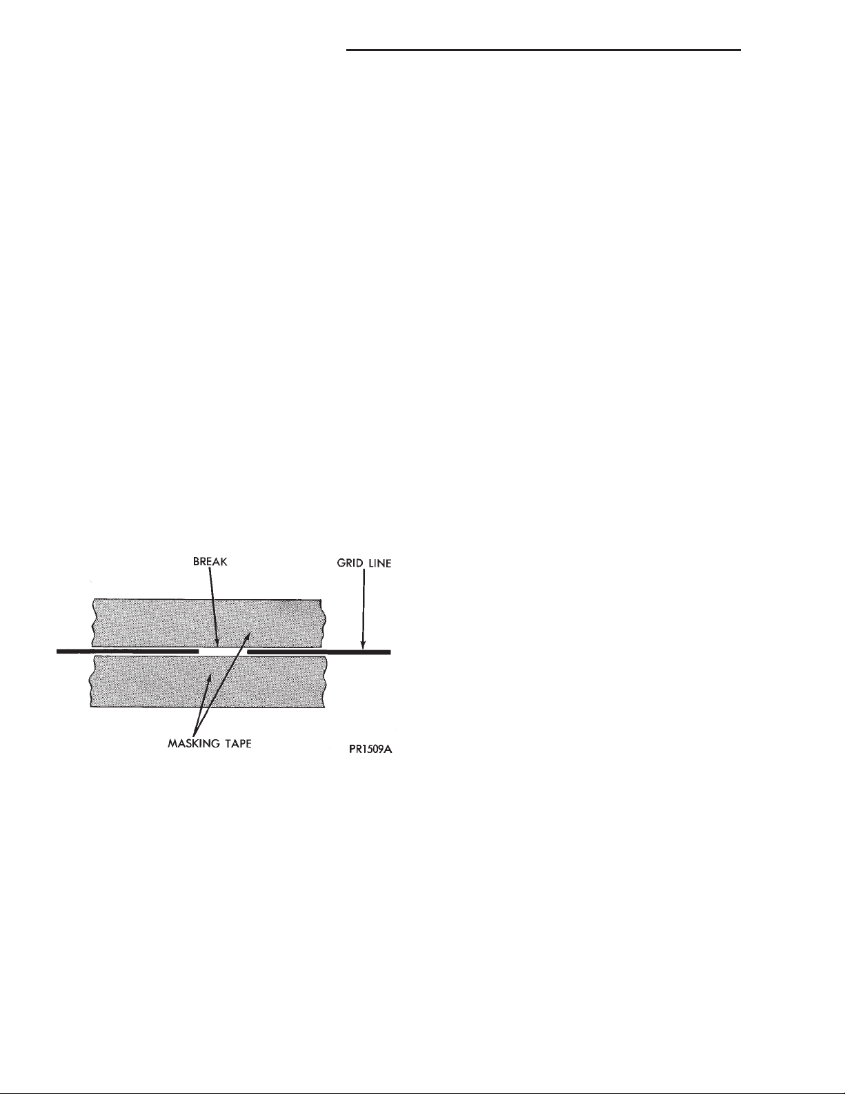
(1) Mask the repair area so that the conductive
epoxy can be applied neatly. Extend the epoxy application onto the grid line or the bus bar on each side
of the break (Fig. 4).
bus bar. Apply a thin layer of epoxy to the area
where the terminal or pigtail wire was fastened and
onto the adjacent grid line.
(7) Apply a thin layer of conductive epoxy to the
terminal or bare wire end of the pigtail and place it
in the proper location on the bus bar. To prevent the
terminal or pigtail wire from moving while the epoxy
is curing, it must be wedged or clamped.
(8) Carefully remove the masking tape or template.
CAUTION: Do not allow the glass surface to exceed
204° C (400° F) or the glass may fracture.
(9) Allow the epoxy to cure 24 hours at room temperature, or use a heat gun with a 260° to 371° C
(500° to 700° F) range for fifteen minutes. Hold the
heat gun approximately 25.4 centimeters (10 inches)
from the repair.
(10) After the conductive epoxy is properly cured,
remove the wedge or clamp from the terminal or pigtail wire. Do not attach the wire harness connectors
until the curing process is complete.
(11) Check the operation of the rear window defogger glass heating grid.
REMOVAL AND INSTALLATION
Fig. 4 Grid Line Repair - Typical
(2) Follow the instructions in the repair kit for
preparing the damaged area.
(3) Remove the package separator clamp and mix
the two conductive epoxy components thoroughly
within the packaging. Fold the package in half and
cut the center corner to dispense the epoxy.
(4) For grid line repairs, mask the area to be
repaired with masking tape or a template.
(5) Apply the epoxy through the slit in the masking tape or template. Overlap both ends of the break
by at least 19 millimeters (0.75 inch).
(6) For a terminal or pigtail wire replacement,
mask the adjacent areas so the epoxy can be
extended onto the adjacent grid line as well as the
DEFOGGER SWITCH
WARNING: ON VEHICLES EQUIPPED WITH AIRBAGS, REFER TO GROUP 8M - PASSIVE
RESTRAINT SYSTEMS BEFORE ATTEMPTING ANY
STEERING WHEEL, STEERING COLUMN, OR
INSTRUMENT PANEL COMPONENT DIAGNOSIS OR
SERVICE. FAILURE TO TAKE THE PROPER PRECAUTIONS COULD RESULT IN ACCIDENTAL AIRBAG DEPLOYMENT AND POSSIBLE PERSONAL
INJURY.
(1) Disconnect and isolate the battery negative
cable.
(2) Remove the center bezel from the instrument
panel. See Instrument Panel Center Bezel in Group
8E - Instrument Panel Systems for the procedures.
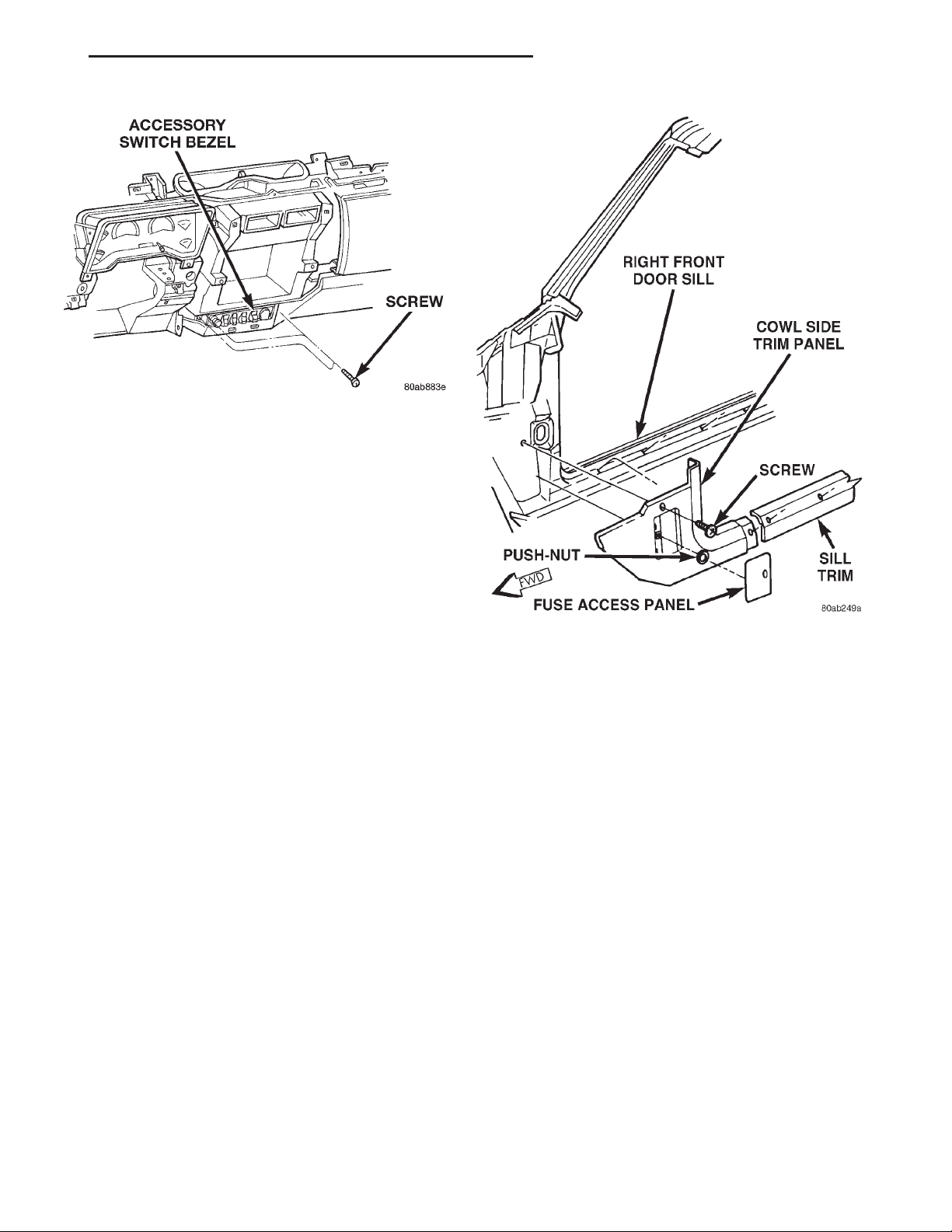
(3) Remove the three screws that secure the accessory switch bezel to the instrument panel (Fig. 5).
(4) Pull the accessory switch bezel out from the
instrument panel far enough to access the wire harness connectors.
(5) Unplug the wire harness connectors from the
rear of the accessory switches and the cigar lighter/
power outlet.
(6) Remove the accessory switch bezel from the
instrument panel.
Page 7
XJ ELECTRICALLY HEATED SYSTEMS 8N - 7
REMOVAL AND INSTALLATION (Continued)
Fig. 5 Accessory Switch Bezel Remove/Install
(7) With a small thin-bladed screwdriver, gently
pry the snap clips at the top and bottom of the rear
window defogger switch receptacle on the back of the
accessory switch bezel and pull the switch out of the
bezel.
(8) Reverse the removal procedures to install. Be
certain that both of the switch snap retainers in the
receptacle on the back of the accessory switch bezel
are fully engaged. Tighten the mounting screws to
2.2 N·m (20 in. lbs.).
DEFOGGER RELAY
WARNING: ON VEHICLES EQUIPPED WITH AIRBAGS, REFER TO GROUP 8M - PASSIVE
RESTRAINT SYSTEMS BEFORE ATTEMPTING ANY
STEERING WHEEL, STEERING COLUMN, OR
INSTRUMENT PANEL COMPONENT DIAGNOSIS OR
SERVICE. FAILURE TO TAKE THE PROPER PRECAUTIONS COULD RESULT IN ACCIDENTAL AIRBAG DEPLOYMENT AND POSSIBLE PERSONAL
INJURY.
(1) Disconnect and isolate the battery negative
cable.
(2) Remove the fuse access panel by unsnapping it
from the right cowl side trim panel.
(3) Remove the stamped nut that secures the right
cowl side trim to the junction block stud (Fig. 6).
(4) Remove the screw located above the fuse access
opening that secures the right cowl side trim to the
right cowl side inner panel.
Fig. 6 Right Cowl Side Trim Remove/Install
(5) Remove the screw that secures the right door
sill trim and the right cowl side trim to the right
door opening sill.
(6) Remove the right cowl side trim panel from the
vehicle.
(7) Unplug the rear window defogger relay from
the junction block.
(8) Install the defogger relay by aligning the relay
terminals with the cavities in the junction block and
pushing the relay firmly into place.
(9) Connect the battery negative cable.
(10) Test the relay operation.
(11) Reinstall the right cowl side trim and the fuse
access panel. Tighten the mounting screws to 2.2
N·m (20 in. lbs.).
Page 8

8N - 8 ELECTRICALLY HEATED SYSTEMS XJ
HEATED SEAT SYSTEM
INDEX
page page
GENERAL INFORMATION
INTRODUCTION ......................... 8
DESCRIPTION AND OPERATION
HEATED SEAT ELEMENT and SENSOR ........ 9
HEATED SEAT RELAY ..................... 9
HEATED SEAT SWITCH ....................8
SEAT HEAT INTERFACE MODULE ............ 9
DIAGNOSIS AND TESTING
HEATED SEAT ELEMENT and SENSOR ....... 10
GENERAL INFORMATION
INTRODUCTION
Individually controlled electrically heated front
seats are available factory-installed optional equipment on this model. The seat heaters will only operate when the ignition switch is in the ON position,
and the surface temperature at the front seat heating
element sensors is below the designed temperature
set points of the system. The heated seat system will
not operate in ambient temperatures greater than
about 32° C (90° F).
There are separate momentary, tactile, two-directional rocker switches located in the center console
with center NEUTRAL, HI and LO positions for each
front seat. Depressing the rocker switch to its
momentary HI or LO position signals the Seat Heat
Interface Module (SHIM) to power the selected
heated seat and maintain the requested temperature
setting (HI or LO). Each switch has a HI and LO
Light-Emitting Diode (LED) which, via the SHIM,
illuminates to give a visual indication that the system is in the HI or LO mode. The LO heat set point
is about 32° C (90° F), and the HI heat set point is
about 38° C (100° F). The system shall be deactivated
whenever the same set position is depressed a second
time and shall change states directly when switching
from HI to LO or vice versa. The system shall be
deactivated whenever the ignition switch is placed in
the off position. When the ignition switch is placed
back in the run position, the heated seat system
shall remain deactivated until a momentary switch is
depressed. When a seat heater is turned on, a sensor
located near the seat cushion electric heater element
provides the SHIM with input indicating the surface
temperature of the seat cushion. If the surface temperature input is below the temperature set point of
the SHIM for the selected temperature setting, an
HEATED SEAT RELAY .................... 11
HEATED SEAT SWITCH ................... 10
HEATED SEAT SYSTEM ................... 9
SEAT HEAT INTERFACE MODULE ........... 11
REMOVAL AND INSTALLATION
HEATED SEAT RELAY ....................12
HEATED SEAT SWITCH ................... 12
SEAT HEAT INTERFACE MODULE ...........12
N-FET Transistor within the SHIM energizes the
heating elements in the seat cushion and back. When
the sensor input indicates the correct temperature
set point has been achieved, the SHIM de-energizes
the N-FET. The SHIM will continue to cycle the
N-FET as needed to maintain the temperature set
point.
The SHIM will automatically turn off the heating
elements if it detects a short in the heating element
or a sensor out of range. These conditions will also
cause the SHIM to notify the occupant of the failure
via flashing the heated seat switch LED’s as discussed later.
Switched battery power to the SHIM is supplied by
the heated seat relay mounted to the seat cushion
frame with the SHIM under the right front seat. The
battery feed is protected by a circuit breaker located
in the junction block.
Following are general descriptions of the major
components in the heated seat system. Refer to
8W-63 - Power Seat With Heated Seats in Group 8W
- Wiring Diagrams for complete circuit descriptions
and diagrams.
DESCRIPTION AND OPERATION
HEATED SEAT SWITCH
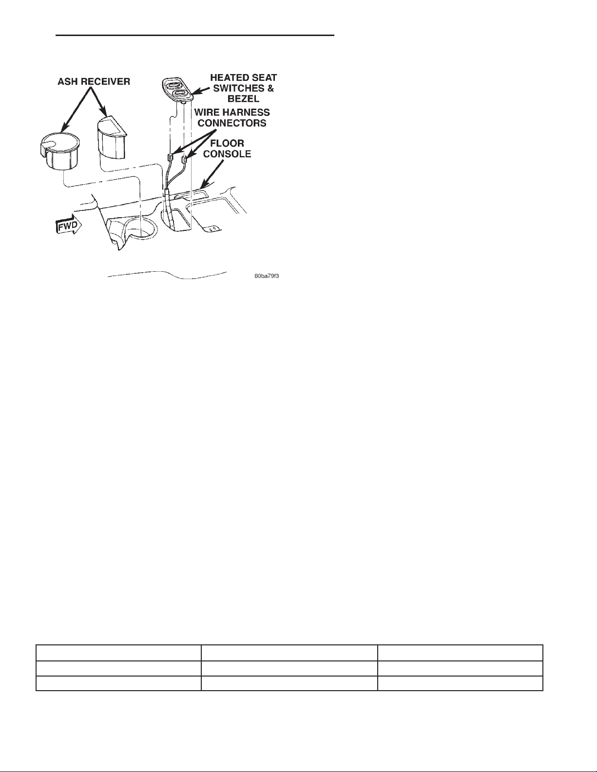
The heated seat switch assembly is located on the
center console where the ashtray is normally located
(Fig. 1). The two momentary, two-directional rocker
switches, one switch for each front seat, provide a
resistor-multiplexed signal to the Seat Heat Interface
Module (SHIM). Each switch has center NEUTRAL,
and momentary LO and HI positions so that both the
driver and the front seat passenger can select a preferred seat heating mode.
Each switch has two telltales (LED’s) which indicate the mode of the heater of the respective seat.
Page 9
XJ ELECTRICALLY HEATED SYSTEMS 8N - 9
DESCRIPTION AND OPERATION (Continued)
HEATED SEAT ELEMENT and SENSOR
Two heated seat heating elements are used in each
front seat, one for the seat cushion and the other for
the seat back. The two elements for each seat are
connected in series with the SHIM.
The temperature sensor is a Negative Temperature
Coefficient (NTC) thermistor. One temperature sensor is used for each seat, and it is integral to the seat
cushion heating element.
The heating elements are sewn into the seat cushion
cover and seat back cover assemblies, which are serviced individually. The heating elements and temperature sensor cannot be repaired and, if faulty or
damaged, the affected seat cover assembly must be
replaced. Refer to Group 23 - Body for the seat cushion
cover and seat back cover Removal and Installation.
DIAGNOSIS AND TESTING
Fig. 1 Heated Seat Switch Location
The switches also have LED’s which provide backlighting when the ignition switch is in the ON position. The LED’s cannot be repaired. If the LED is
faulty, the individual switch must be replaced.
HEATED SEAT SYSTEM
For circuit descriptions and diagrams, refer to 8W 63 - Power Seat With Heated Seats in Group 8W Wiring Diagrams.
SEAT HEAT INTERFACE MODULE
The Seat Heat Interface Module (SHIM) is an electronic microprocessor controlled device designed to
operate the electric seat heater elements. The SHIM
is located under the right front seat cushion. Inputs
to the module include the console mounted resistor
multiplexed switch signals, seat cushion temperature
sensors, a relay-switched battery feed, and a ground.
The SHIM outputs are the feed for the seat heating
elements and sensors, and the switch telltale circuits.
The SHIM cannot be repaired and, if faulty or damaged, it must be replaced.
HEATED SEAT RELAY
The heated seat relay is located under the right
front seat cushion near the SHIM. Ignition and battery power is fed to the relay, which then provides a
switched battery feed to the SHIM. The heated seat
relay cannot be repaired and, if faulty or damaged, it
must be replaced.
SEAT HEAT INTERFACE MODULE DIAGNOSTIC ROUTINES
WARNING: ON VEHICLES EQUIPPED WITH AIRBAGS, REFER TO GROUP 8M - PASSIVE
RESTRAINT SYSTEMS BEFORE ATTEMPTING ANY
STEERING WHEEL, STEERING COLUMN, OR
INSTRUMENT PANEL COMPONENT DIAGNOSIS OR
SERVICE. FAILURE TO TAKE THE PROPER PRECAUTIONS COULD RESULT IN ACCIDENTAL AIRBAG DEPLOYMENT AND POSSIBLE PERSONAL
INJURY.
The heated seat system is capable of performing
some self-diagnostics. The following table depicts the
various failure modes which will be reported to the
occupant via flashing the momentary switch telltales.
The switch telltales will flash on the driver’s switch if
the failure exists in the driver’s seat portion of the system, similarly with the passenger’s switch. The telltale
will illuminate for approximately a
second off pulse for a duration of one minute. This process will repeat every time the system is initiated via
the switches until the problem has been corrected.
1
⁄2second on,1⁄
2
FAILURE MODE SWITCH 9HI9 TELLTALE SWITCH 9LO9 TELLTALE
Shorted Heating Element Flashing Flashing
NTC Value Out of Range Off Flashing
Page 10

8N - 10 ELECTRICALLY HEATED SYSTEMS XJ
DIAGNOSIS AND TESTING (Continued)
Before testing the individual components in the
heated seat system, check the following:
• If the heated seat switch backlighting does not
illuminate with the ignition switch in the ON position, check the fuse in the junction block. If the fuse
is OK, see Heated Seat Switch Backlighting in the
Diagnosis and Testing section of this group. If not
OK, repair the shorted circuit or component as
required and replace the faulty fuse.
• If the heated seat switch telltales do not illuminate with the ignition switch in the ON position, but
the heating elements do heat, see Heated Seat
Switch Telltales in the Diagnosis and Testing section
of this group.
• If the heated seat switch backlighting illuminates with the ignition switch in the ON position,
but the heating elements do not heat and the telltales do not illuminate, check the circuit breaker in
the junction block. If the circuit breaker is OK, see
Heated Seat Switch Multiplexed Resistances in the
Diagnosis and Testing section of this group. If not
OK, replace the faulty circuit breaker.
• If the heated seat switch backlighting illuminates and the telltales illuminate, but the heating
elements do not heat; see Heated Seat Element in
the Diagnosis and Testing section of this group.
HEATED SEAT SWITCH
For circuit descriptions and diagrams, refer to 8W 63 - Power Seat With Heated Seats in Group 8W Wiring Diagrams.
WARNING: ON VEHICLES EQUIPPED WITH AIRBAGS, REFER TO GROUP 8M - PASSIVE
RESTRAINT SYSTEMS BEFORE ATTEMPTING ANY
STEERING WHEEL, STEERING COLUMN, OR
INSTRUMENT PANEL COMPONENT DIAGNOSIS OR
SERVICE. FAILURE TO TAKE THE PROPER PRECAUTIONS COULD RESULT IN ACCIDENTAL AIRBAG DEPLOYMENT AND POSSIBLE PERSONAL
INJURY.
BACKLIGHTING
(1) Disconnect and isolate the battery negative
cable
(2) Remove the heated seat switch assembly from
the center console. Remove the connector from the
suspect switch. Check for continuity between the
ground circuit cavity of the 6-way heated seat switch
wire harness connector and a good ground. There
should be continuity. If OK, go to Step 3. If not OK,
repair the open circuit as required.
(3) Connect the battery negative cable. Turn the
ignition switch to the ON position. Check for battery
voltage at the fused ignition switch output circuit
cavity of the 6-way heated seat switch wire harness
connector. If OK, turn the ignition switch to the OFF
position, disconnect and isolate the battery negative
cable, and replace the heated seat switch. If not OK,
repair the open circuit as required.
TELLTALES
(1) Replace the heated seat switch with a known
good unit and test the operation of the switch telltales. If OK, discard the faulty heated seat switch. If
not OK, see Seat Heat Interface Module in the Diagnosis and Testing section of this group.
MULTIPLEXED RESISTANCES
(1) Disconnect and isolate the battery negative
cable.
(2) Remove the heated seat switch assembly from
the center console. Remove the connector from the
suspect switch.
(3) With the suspect heated seat switch in the
NEUTRAL position, using an ohmmeter, measure the
resistance between the fused ignition switch output
circuit terminal and the heated seat switch output
circuit terminal in the 6-way connector receptacle on
the back of the switch. The resistance reading should
be about 2.2. Kohms. If OK, go to Step 4. If not OK,
replace the faulty switch.
(4) Hold the suspect heated seat switch in the LO
position. Using an ohmmeter, check the resistance
between the fused ignition switch output circuit terminal and the heated seat switch output circuit terminal in the 6-way connector receptacle on the back
of the switch. The resistance reading should be about
414 Ohms. If OK, go to Step 5. If not OK, replace the
faulty switch.
(5) Hold the suspect heated seat switch in the HI
position. Using an ohmmeter, check the resistance
between the fused ignition switch output circuit terminal and the heated seat switch output circuit terminal in the 6-way connector receptacle on the back
of the switch. The resistance reading should be about
32.5 Ohms. If OK, see Heated Seat Relay in the
Diagnosis and Testing section of this group. If not
OK, replace the faulty switch.
HEATED SEAT ELEMENT and SENSOR
The wire harness connectors for the seat cushion
and seat back heating elements are located under the
seat, near the rear edge of the seat cushion frame.
For circuit descriptions and diagrams, refer to 8W 63 - Power Seat With Heated Seats in Group 8W Wiring Diagrams.
SEAT CUSHION
(1) Disconnect and isolate the battery negative
cable. Unplug the 4-way heated seat cushion wire
harness connector.
Page 11

XJ ELECTRICALLY HEATED SYSTEMS 8N - 11
DIAGNOSIS AND TESTING (Continued)
(2) Check for continuity between the two heated
seat element circuit cavities of the seat cushion cover
half of the heated seat cushion wire harness connector. There should be continuity. If OK, go to Step 3. If
not OK, replace the faulty seat cushion cover.
(3) Check for continuity between one of the heated
seat element circuit cavities of the seat cushion cover
half of the heated seat cushion wire harness connector and the seat cushion frame. There should be no
continuity. If OK, see Seat Back in the Diagnosis and
Testing section of this group. If not OK, replace the
faulty seat cushion cover.
SEAT BACK
(1) Disconnect and isolate the battery negative
cable. Unplug the 2-way heated seat back wire harness connector.
(2) Check for continuity between the heated seat
element circuit cavity and the ground circuit cavity of
the seat back cover half of the heated seat back wire
harness connector. There should be continuity. If OK,
go to Step 3. If not OK, replace the faulty seat back
cover.
(3) Check for continuity between the heated seat
element circuit cavity of the seat back cover half of
the heated seat back wire harness connector and the
seat back frame. There should be no continuity. If
OK, see Heated Seat Sensor in the Diagnosis and
Testing section of this group. If not OK, replace the
faulty seat back cover.
HEATED SEAT SENSOR
The wire harness connector for the seat cushion
heating element and sensor are located under the
seat, near the rear edge of the seat cushion frame.
For circuit descriptions and diagrams, refer to 8W 63 - Power Seat With Heated Seats in Group 8W Wiring Diagrams.
(1) Disconnect and isolate the battery negative
cable. Unplug the 4-way heated seat cushion wire
harness connector.
(2) Using an ohmmeter, check the resistance
between the heated seat sensor input circuit cavity
and the heated seat sensor feed circuit cavity of the
seat cushion cover half of the heated seat cushion
wire harness connector. The sensor resistance should
be between 1 Kohm and 200 Kohms. If OK, see
Heated Seat Relay in the Diagnosis and Testing section of this group. If not OK, replace the faulty seat
cushion cover.
HEATED SEAT RELAY
For circuit descriptions and diagrams, refer to 8W 63 - Power Seat With Heated Seats in Group 8W Wiring Diagrams.
(1) Disconnect and isolate the battery negative
cable. Unplug the 8-way heated seat relay connector.
(2) Check for continuity between the ground circuit cavity of the 8-way heated seat relay wire harness connector and a good ground. There should be
continuity. If OK, go to Step 3. If not OK, repair the
open circuit as required.
(3) Connect the battery negative cable. Check for
battery voltage at the battery feed circuit cavity (pin
8) of the 8-way heated seat relay wire harness connector. If OK, go to Step 4. If not OK, repair the open
circuit as required.
(4) Turn the ignition switch to the ON position.
Check for battery voltage at the fused ignition switch
output circuit cavity of the 8-way heated seat relay
wire harness connector. If OK, turn the ignition
switch to the OFF position, disconnect and isolate
the battery negative cable, and go to Step 5. If not
OK, repair the open circuit as required.
(5) Unplug the 14-way seat heat interface module
(SHIM) connector. Check for continuity between the
two switched battery feed cavities of the 14-way
SHIM wire harness connector and the switched battery feed cavity of the 8-way heated seat relay wire
harness connector. If OK, reconnect the heated seat
relay wire harness connector, and go to Step 6. If not
OK, repair the open circuit as required.
(6) Connect the battery negative cable. Turn the
ignition switch to the ON position. Check for battery
voltage at the switched battery feed cavities of the
14-way SHIM wire harness connector. If OK, turn
the ignition switch to the OFF position, disconnect
and isolate the battery negative cable, and see Seat
Heat Interface Module in the diagnosis and testing
section of this group. If not OK, replace the heated
seat relay.
SEAT HEAT INTERFACE MODULE
Before testing the seat heat interface module, test
the heated seat switch, the heated seat elements, and
the heated seat sensor as described in the Diagnosis
and Testing section of this group. If testing of the
heated seat switch, elements, and sensor reveals no
problems, proceed as follows. For circuit descriptions
and diagrams, refer to 8W - 63 - Power Seat With
Heated Seats in Group 8W - Wiring Diagrams.
(1) Replace the seat heat interface module with a
known good unit and test the operation of the heated
seats. If OK, discard the faulty seat heat interface
module. If not OK, go to Step 2.
(2) Test each of the circuits from the heated seat
switch, heated seat relay, heated seat elements, and
heated seat sensor to the seat heat interface module.
Repair any short or open circuits as required.
Page 12

8N - 12 ELECTRICALLY HEATED SYSTEMS XJ
REMOVAL AND INSTALLATION
HEATED SEAT SWITCH
WARNING: ON VEHICLES EQUIPPED WITH AIRBAGS, REFER TO GROUP 8M - PASSIVE
RESTRAINT SYSTEMS BEFORE ATTEMPTING ANY
STEERING WHEEL, STEERING COLUMN, OR
INSTRUMENT PANEL COMPONENT DIAGNOSIS OR
SERVICE. FAILURE TO TAKE THE PROPER PRECAUTIONS COULD RESULT IN ACCIDENTAL AIRBAG DEPLOYMENT AND POSSIBLE PERSONAL
INJURY.
(1) Disconnect and isolate the battery negative
cable.
(2) Using a trim stick or another suitable wide
flat-bladed tool, gently pry around the perimeter
edges of the heated switch assembly bezel to release
the assembly from the console. Remove the assembly
from the console.
(3) Pull the switch assembly out from the console
far enough to access and unplug the wire harness
connectors.
(4) Remove the heated seat switch assembly from
the console.
(5) Remove the heated seat switch(es) from the
heated seat switch assembly.
(6) Reverse the removal procedures to install.
SEAT HEAT INTERFACE MODULE
(1) Move the right power seat adjuster to its full
up and full rear stop positions.
(2) Disconnect and isolate the battery negative
cable.
(3) Unhook the seat cushion cover retainer from
the seat cushion frame and pull back the seat cushion cover.
(4) Pull back the seat cushion to allow access to
the Seat Heat Interface Module (SHIM).
(5) Pull the SHIM upward to release the two
mounting fasteners from either the module or the
mounting bracket. Unplug the wire harness connector from the module.
WARNING: THERE ARE MANY SHARP METAL
EDGES ON THE SEAT CUSHION FRAME AND SEAT
ADJUSTER RAILS UNDER THE SEAT. WHEN PERFORMING THIS SERVICE, A LONG-SLEEVED SHIRT
AND GLOVES SHOULD BE WORN IN ORDER TO
AVOID UNNECESSARY CUTS AND ABRASIONS TO
EXPOSED SKIN.
(6) Reverse the removal procedures to install. Be
certain that the SHIM terminals are aligned with the
cavities in the wire harness connector before pushing
the module firmly into place.
HEATED SEAT RELAY
(1) Move the right power seat adjuster to its full
up and full rear stop positions.
(2) Disconnect and isolate the battery negative
cable.
(3) Unhook the seat cushion cover retainer from
the seat cushion frame and pull back the seat cushion cover.
(4) Pull back the seat cushion to allow access to
the Heated Seat Relay.
(5) Cut the Christmas tree fastener to remove the
Heated Seat Relay fastener from the mounting
bracket. Unplug the wire harness connector from the
relay.
(6) Reverse the removal procedures to install. A
new Christmas tree fastener must be used to mount
the relay. Be certain that the relay terminals are
aligned with the cavities in the wire harness connector before pushing the relay firmly into place.
 Loading...